
1.Overview Of Signal Flow Designer
The Signal Flow Designer allows you to create a visual representation of a signal flow.
The process of creating a signal flow involves dragging and dropping audio objects onto a virtual canvas, connecting them using virtual connections, and adjusting the settings for each component. Once the signal flow is defined, it can then send to the amplifier or other devices in the signal chain to process the audio and control signals according to the defined flow.
GTT allows you to create and modify signal flows in real-time, which is particularly useful in live tuning. Live tuning can be dynamic and unpredictable, and signal flow designers can help audio professionals to make real-time changes to the signal chain to ensure the best possible sound quality and performance.

2.Components of Signal Flow Designer
The Signal Flow Designer enables you to create and modify signal flows architecture. It includes a variety of components that you can use to design a signal flow. The components in the Signal Flow Designer are represented as blocks and you can connect them using virtual connections to create a signal path. You can also adjust various parameters of each component to customize the signal flow according to your needs.

Signal Flow Designer includes the following components:
2.1.Toolbox
The toolbox is a library of audio objects. In SFD, you can create compound audio objects by combining multiple audio objects into a signal audio object. These compound audio objects can be saved and reused in the same and other signal flow designs. Additionally, you can import compound audio objects into SFD using the import option.
Use the search option to locate the audio object in the toolbox. To find the desired audio object, enter the first three or more characters in the toolbox’s search bar.
The audio objects displayed in the toolbox based on the default device audio library version.
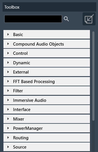
Regardless of the audio Library, two objects are always available in the Toolbox by default. The objects “Frame” and “Textbox” can be found in the Shapes category in the toolbox. These are not audio objects, and they are not considered when tuning or sending the signal flow to the device.
The frame object is used to highlight certain blocks in the signal flow designer. Whereas the Textbox object is used to provide additional information to the user of the Signal Flow.
For more information about various audio objects, refer to the Audio Object Description Guide.
2.2.Design Operations
This section contains several operations you can perform in a signal flow design.

Following are operations you can perform in a signal flow design.
- Reset a Processing state(s): In signal flow designer you can reset all audio objects processing state to ‘Normal’ by using the “Reset” button.
- Connect Audio Blocks: When designing a signal flow for processing audio signals, there are different types of audio objects that are used to create the audio signal. To create a meaningful audio signal, you need to connect these blocks in a signal flow. This concept is called routing.
Routing is the process of directing an audio signal from one block to another. In a typical signal flow, various audio objects are connected from input to output using virtual connections to route the audio signal from one block to another.
You can connect all audio objects with a single click using the “Connect Block” option. Later, you can modify the connections as per your requirenment. - Saving Signal Flow Designer: When working with a signal flow designer, it’s important to save your work regularly to prevent data loss. This ensures that you can return to your project at a later time. Click on the “Save” option to save the changes in the signal flow design.
- Extracting Audio Object: Extract can be performed only when valid audio objects are selected. Currently, the GTT does not support FIR MIMO, EOC, RNC, Audio IO, Control IN, Compound Audio Object extraction.
Extract will be enabled only if Signal Flow is saved.
For extracting audio object, you need to select one or more audio objects from an existing signal flow and extract audio objects into a Compound Audio Object. The application will replace the extracted audio objects with the Compound Audio Object in the signal flow.
For more details about compound audio objects, refer to Compound Audio Object.
- Search Audio Object: Using the search option you can locate specific audio objects in the signal flow designer. The located audio object highlighted in yellow color.
You can use the “<<” and “>>” buttons to move between the highlighted audio objects. When you click the “<<” or “>>” search buttons, the highlighted audio object will be repositioned to the center of the screen. - Redo/Undo: The redo and undo option allows you to redo or undo the changes that you have made to your audio project.
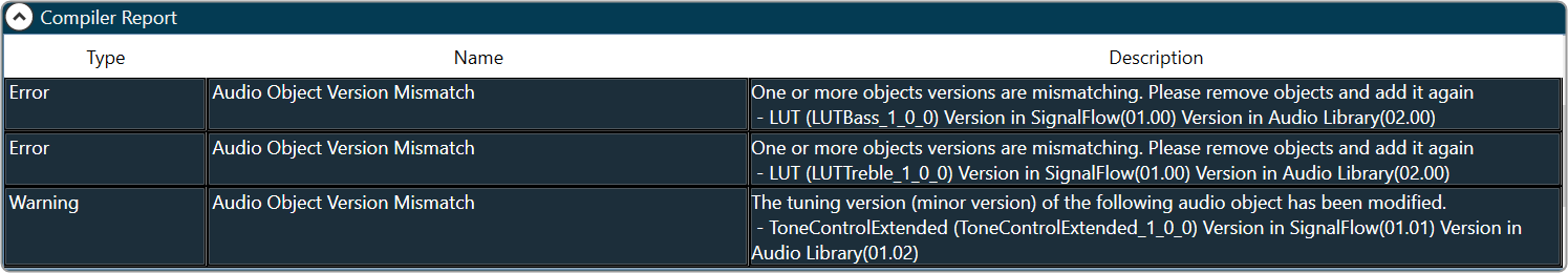
Press Ctrl+Z to perform Undo operatoion and Press Ctrl+Y to perform Redo operation. - Complier Report: The compiler report displays a warning or error message entry item for each invalid audio objects.

Following are the few factors are responsible for invalid signal flow design:
- If the audio object tuning version differs from the existing audio object type in the Device Associated Audio Library.
- Due to addition or modification of parameters of an audio object, it might mismatch with the signal flow design state.
To resolve the issue, you need to upgrade the audio object, refer Upgrade Audio Object for more details.
2.3.Properties View
You can view the properties of an audio object used in the signal flow design through the Properties view. This allows you to configure the properties of the audio object to suit your requirements. The properties can be viewed by selecting a specific audio object.

Audio Object Modes
Some audio blocks support multiple configuration modes. For instance, the AudioIO block can function as both an audio input and an audio output block. Similarly, the Biquads block can operate either as a parameters-based or coefficients-based Biquad.
In previous versions of the Signal Flow Designer, each mode of an audio block was displayed as a separate audio block. However, in the latest version of the tool, it is assumed that every block can support at least one configuration mode.
For those blocks that support multiple modes, an extra drop-down field is now shown on the properties view. By selecting an appropriate value from the drop-down, you can modify the mode.

Control Configuration
In the latest version of GTT, the Signal Flow Designer supports control routing from the control hub (Master Control) to xAF framework instances.
The ControlIn block is used to configure a control flow for each instance. By designating certain control signals to the output pins of a ControlIn block within a given instance, you can decide which control signals that instance will receive. To make the process easier, a new tab is added to the property configuration.
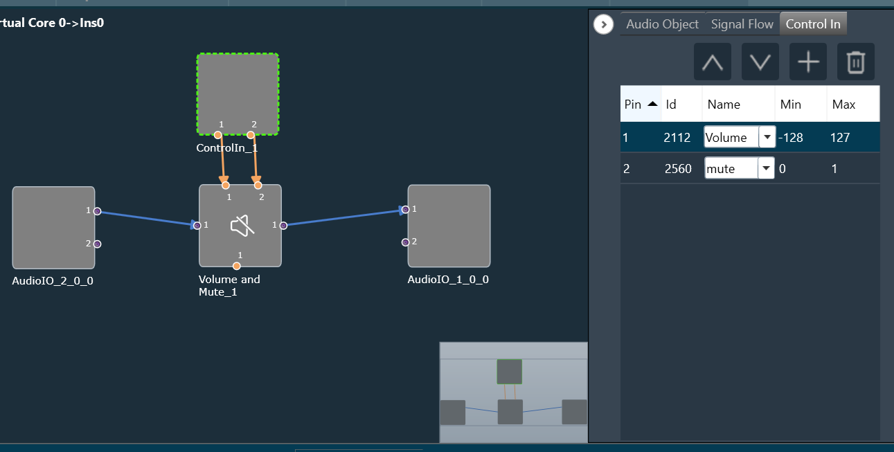
Using that tab, you can choose from a wide list of available control signals and associate them with control outputs of the ControIln block. Re-ordering of the items in the control signals grid is done via the Up and Down buttons.
You can also define your own custom control signals (Control IDs) and assign them to control pins.
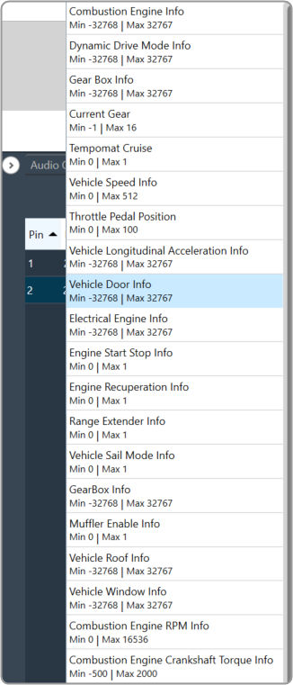
When a custom Control ID is defined for a device, it can be accessed in the Control In tab of any ControlIn audio object, along with the predefined Control IDs.
In terms of tuning, the custom control signals are treated as part of the Master Class object, just like the predefined control signals.
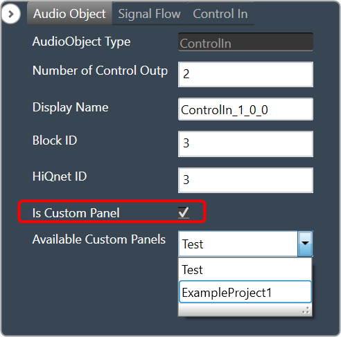
Mapping Custom Panel
Open any audio object property view, enable “Is Custom Panel” option, and select the appropriate custom panel from the drop-down list.
For details about creating a custom panel in GTT, refer to link Create a Custom Panel in GTT.
2.4.Audio Object Operations
You can access these operations by right-clicking on any audio object and selecting them from the context menu. Below are the options available in the context menu.
- Add Audio Pin Label
- Add Control Pin Label
- Dynamic Metadata
- Open Audio Configuration Panel
- Open column name Configuration panel
- Upgrade audio object
- Processing State

3.Operations in Signal Flow Designer
3.1.Pin Labelling
A signal flow designer can assign labels to audio and control pins of audio objects to make a flowchart design more informative. There are two items available in the context menu of each audio object “Add Audio Pin Label” and “Add Control Pin Label”.
The process of signal flow design involves the labelling of audio and control pins for audio objects, which enhances the clarity of the flowchart design. To facilitate this, there are two options available in the context menu of each audio object: “Add Audio Pin Label” and “Add Control Pin Label.”
Pin labels are not propagated downstream by default, although certain objects such as Gain, Biquad, or Delay do have this capability. For a design with four blocks like AudioIn, Gain, Delay, and AudioOut. Label the output channels of the AudioIn block, select all the blocks, and then press the “Connect Blocks” button. This is sufficient to propagate the labels, since they will be inherited by the downstream objects.
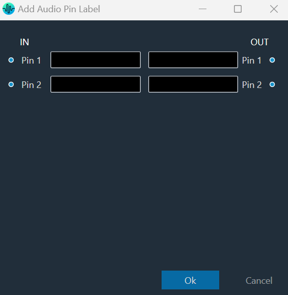
To Add Audio Pin Label
- On the signal flow designer, right-click on the audio object, and select Add Audio Pin Label. This opens the Add Audio Pin Label dialogue box.

- On the pin label dialogue box, enter the input pin and output pin details and click Ok. The label will be displayed on the audio object.
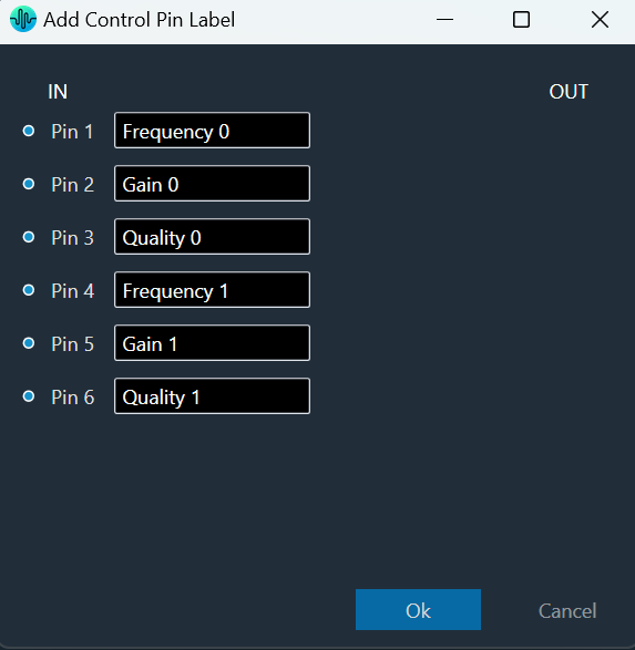
To Add Control Pin Label
- On the signal flow designer, right-click on the audio object, and select Add Contro Pin Label. This opens the Add Control Pin Label dialogue box.

- On the control label dialogue box, enter the input pin and output pin details and click Ok. The label will be displayed on the audio object.
Tooltip
A tooltip is a graphical user interface (GUI) element that appears when you hover over pin connections. It typically contains a brief description or additional information about the pin connection. Tooltip can be used to obtain more detailed information on the connection between Audio Objects (AOs), tooltips are available that display the affected AO names and the corresponding pins used.
To access these tooltips, you must first connect any two AOs, then hover your mouse over the connection presenter (arrow). This will display a tooltip showing the Audio Object Name, Pin No., and Labels (if any) for the connected objects.

3.2.View Audio Object Metadata
In the Signal Flow Designer, you can view static metadata and dynamic metadata of an audio object.
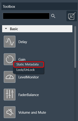
Static Metadata
Static metadata refers to the metadata information of an audio object that does not change frequently. By default, every object available in the toolbox has the static metadata. Right-click on the audio object in the toolbox section to view the static metadata details.
On the metadata dialog box, the following metadata information displayed.

Dynamic Metadata
Dynamic metadata includes metadata information of an audio object that changes frequently or is generated in real-time. Every audio object instance in the signal flow designer has dynamic metadata. Right-click on the audio object in the signal flow designer to view the dynamic metadata details.

On the metadata dialog box, the following metadata information displayed.

3.3.Open column name Configuration Panel
When linked to an object, the Smart LUT feature automates the process of adding column labels semi-automatically rather than manually.
The “Open column name Configuration Panel” feature only supports LUT audio object.
Launching Column Name Panel
You can use this feature to choose which state variable values should be shown as column headers on the LUT panel. To begin assigning state variables to the columns of the LUT panel, simply open the panel by accessing the context menu of the LUT object in the SFD.
SFD must be saved before opening this feature else the state variables will not be available.

Following are the components available on Column Naming Window.
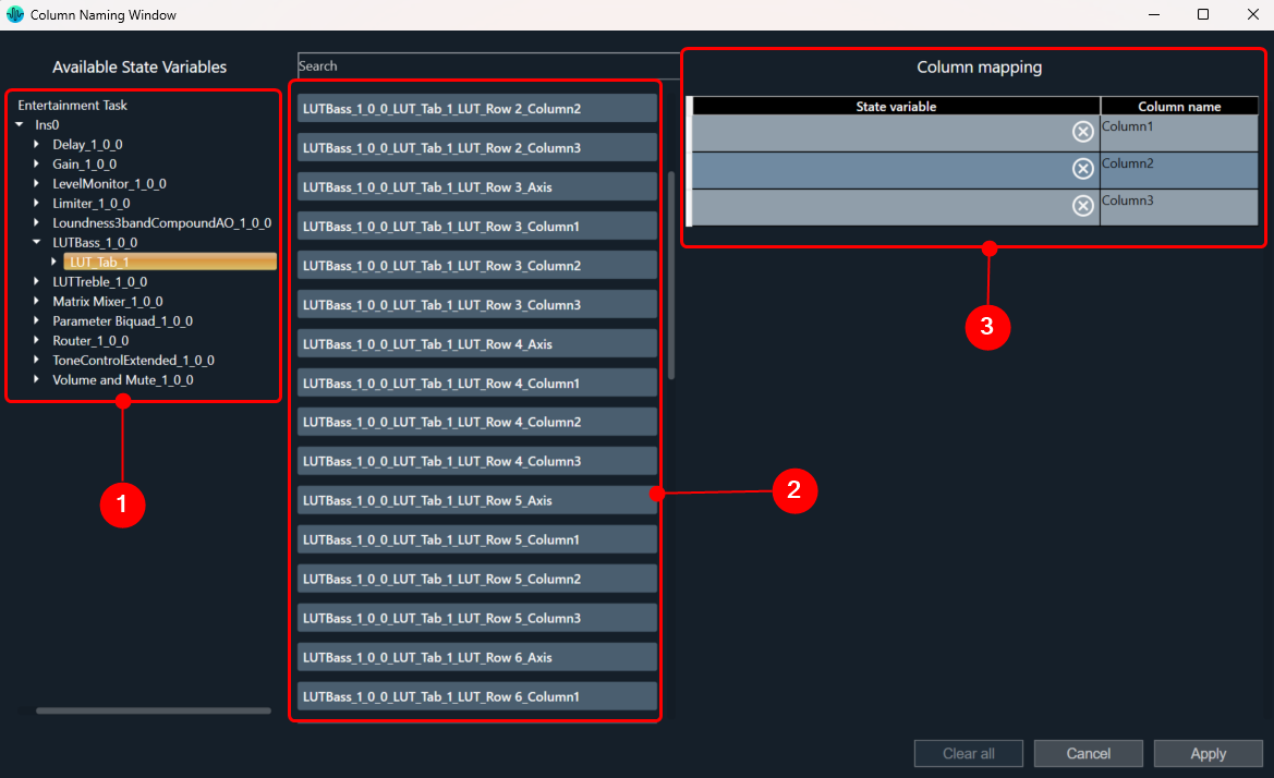
- Tree with all objects
- List with columns details
State variables associated to different objects
State variables can be filtered in two ways:
By clicking on the individual audio objects in the tree – each click will display the state variable of the respective audio object. Multiple objects can be selected to display their state variables.
Or
Use the Search bar and type required text, for example AO name (not case sensitive).
Selecting State Variable
Each state variable can be assigned to only one column. After assigning to column, it will disappear from available state variables.
To assign state variables to a column, select the state variable and drag it to the appropriate column.
- To Select: Multiple state variables can be selected by holding the CTRL key or by clicking the ‘Select all’ button above.
- To Move: For moving selected variables, use the SHIFT key to hold and move the variables.
When all columns are completed, the ‘Apply’ button in the bottom right corner will become active. It will also be enabled if all columns are empty.

To stop using state variables for naming it is necessary to open the Naming panel, clear all variables and apply.
Workaround for LUT Parameter Sets Unit Problem
This workaround is required for projects which are exported earlier than N+1 release.
- Import earlier exported project and open Signal Flow designer.
- If all LUT objects belong to the same group, double-click on any LUT objects to launch the panel.
- If each LUT object belongs to different groups, then launch the panels separately for each group.
- Close the LUT panels.
- Open Parameter sets view, right-click on column header of red color highlighted set, and click ‘Store’ context menu to get latest set values.
You can observe the red highlights are cleared and units are removed for each state variable.
3.4.Upgrade Audio Object
When you launch signal flow designer by double-clicking on the Framework Instance in device view, GTT validates all audio objects that are mismatching with the toolbox. A report is displayed with the version difference of all audio objects, with the option to auto-upgrade them based on the user’s preferences.

If you selects “Yes”, all audio objects will automatically upgraded to the version equivalent to the toolbox version. If any compound audio objects exist. They must be upgraded manually.
If you select “No”, the signal flow will be launched and you need to manually upgrade them.
If the audio object in the signal flow design becomes out of sync as a result of modification. The compiler report will display a warning message, and the audio objects will be highlighted in blue.
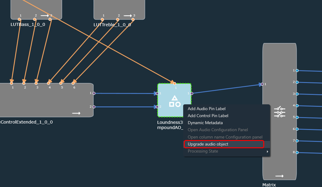
To manually upgrade the audio object to the signal flow designer state; right-click on the highlighted audio object and select “Upgrade Audio Object” from the context menu.
Until N-release, if any audio objects are out of sync with the audio library, GTT will not allow you to save or send the signal flow to a device. To pass the validation, you must manually replace (delete) the current audio objects in the signal flow with the toolbox audio object. All connections and tuning data are lost during this process, which must be redone, resulting in increased effort.
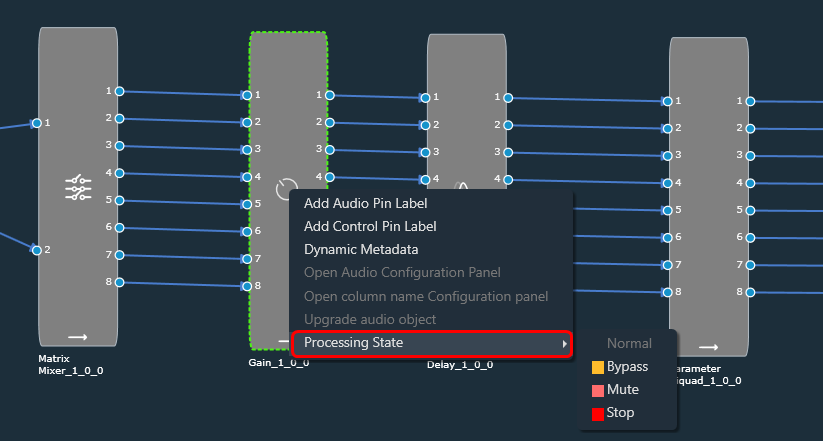
Below image shows the context menu option to choose “Upgrade Audio Object”. When the audio object is upgraded, there will be messages to guide you to the next steps.

The following audio object properties will be upgraded:
- Additional variables (added or deleted)
- Modes (added or deleted)
- Audio object properties like input/output, channels, etc
- Tuning version
The audio objects with major tuning version changes or structural changes, such as additional variable changes, will be detected as incompatible and highlighted in blue. Until all these incompatible AOs are upgraded, signal flow cannot be saved.
Version changes in Tuning will be highlighted in blue and Until all these AOs are upgraded, signal flow cannot be saved.
Tuning data and Parameter sets will be preserved incase of Minor version change while incase of Major version it will not retain data
Example: When the tuning version of an audio object in the signal flow is 04.00 and the version in the toolbox is 04.01, only the minor version has changed. As a result, the tuning data will be saved.
Similarly, if the tuning version of an audio object in the signal flow is 04.00 and the toolbox version is 05.00, tuning data will be lost because the internal structure of the AO has changed.
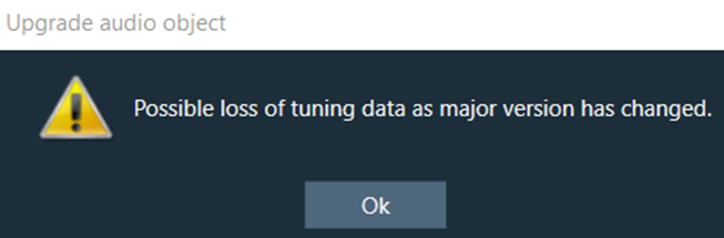
When the upgrade is complete, a message will appear informing the user of the tuning data status.

The above message is a warning that there may be a tuning data loss because the audio library changed the major version in the tuning version. The set group(s) to be modified will be listed in the message.
If no set groups are created using the respective audio object, the following message will be shown.
Upgrade Compound Audio Object (CAO)
The compound audio object (CAO) in the signal flow can also be upgraded. For minor version changes, only the version number will be updated, but no other changes will be made. However, in the case of a major version change in the toolbox, the internal audio object will be updated to the latest version according to the CAO type in the toolbox.
If there is a major version change and the inner objects cannot be automatically upgraded, the CAO will be marked with a blue colour and then you need to upgrade the CAO.
For more details about Compound audio object, refer to the Compound audio object.
To upgrade Compound audio object, follow the below steps:
- On the Signal Flow Designer window, select the compound audio object under the Compound Audio Object category in the toolbox and click Edit through the context menu. This opens the Compound Audio Object editor, where you can view the signal flow of the internal audio objects.

- On the Compound Audio Object editor, right-click on the highlighted audio object, and select Upgrade Audio Object from the context menu.
- Click Save and close the Compound Audio Object editor.
After this modification, the CAO in the signal flow design updated and highlighted in blue color. - Right-click on the highlighted compound audio object, and select Upgrade Audio Object from the context menu.
Once the CAO is successfully upgraded, the GTT will notify you.
Upgrading the block ID will not support, if it is changed from normal format to extended format in the DLL.
3.5.Change Audio Object Processing State
Audio engineers require a method for conducting A/B testing of signal flows and load balancing, as well as a simpler way to troubleshoot tuning data if errors occur.
You can achieve by using “Processing State” functionality, where you can change the audio object processing state.
Processing State function only available when device is connected.
These options are available to all audio objects except interface objects like Audio-In, Audio-Out, Control-In, and Control-Out. For the compound audio object, the selected state will be applied to all inner audio objects.
Following are the tasks carried out on the xAF side for each state:
- Normal: Normal operation with update of necessary internal states of the audio object; normal output.
- Bypass: Normal operation with update of necessary internal states of the audio object; input channel buffer data copied to the output channel buffers.
- Mute: Normal operation with update of necessary internal states of the audio object; output channel buffers cleared.
- Stop: Input channel buffer data copied to the output channel buffers (no update of internal states).
The above states are only available through GTT for regular audio objects, and only Normal and Mute states are available for source objects such as Waveform generators.
Audio object which has a state other than ‘Normal’ cannot be tuned through Native Panel.
Ramping
Linear ramping is provided with a ramp-up or ramp-down time of 50 ms. to ensure a smooth transition between states.
Ramping is not provided for any transitions involving the Bypass state, and each audio object must support it.
For transition between Normal and Stop states, first the output is ramped down from the present state to Mute state and then ramped up to the target state.
Every time you connect GTT to device, audio object states from device are read and applied to signal flow designer. If you reboot the device, the processing states of Audio Objects will set to ‘Normal’.
In signal flow designer you can reset all audio objects processing state to ‘Normal’ by using the ‘Reset’ button.
3.6.Metering the Signal Flow
The Metering functionality in a signal flow design basically measures the audio signal output and control output from an audio object of the discovered device.
The SFD metering feature is available from V release onwards and supports discovered devices.
The following audio objects are compatible with Control Metering functionality.
– LUT
– Control Math
– Control Smooth
– ControlMultiAdder
– ControlIn
– Control Grouper (Level meter is not usable on ControlGrouper’s control outputs until GTT supports level meter on BlockControl outputs)
To use this feature, you need perform following actions:
- You need to enable Streaming functionality in the device view and configure the parameters.
- Then, you need to add Level Meters in the signal flow design. When a device is connected, you can use Level Meter to monitor the audio output (Peak or RMS values) by adding them to the audio out connections. Similarly, control output value can be monitored in level meters for control out connections.

Enabling Streaming Functionality
In order to utilize Metering feature for each core, you need to enable Streaming functionality.
To enable Streaming functionality:
- Open the Device View and select the Virtual core layer of the device.
- Go the Virtual core properties and select the Streaming checkbox. This will enable the Streaming functionality.
Additionally, in the Streaming functionality you need to configure the number of level meters that can be added in the signal flow to monitor control out connections or audio.
A core can be configured with up to 32 level meters, and by default it is set to zero. These values will be sent to device while sending device configuration to allocate required memory for level meter streaming.

All level meters under a core will be deleted if the number of level meters you configure in device view is less than the total number of level meters added in a core.
If you modify any of the Streaming configurations, make sure to perform “Send Device Configuration” operation while connecting device.
Level Meter Panel
The Level Meter panel displays number of maximum allowed level meters , number of added level meters and the color coding for different ranges of audio output values.
If the streaming is enabled and the number of level meters configured for the core is greater than zero, a Level Meter panel appears in the top right corner of the signal flow designer.
By default, the Level Meter panel is collapsed.

Click on the expand option to view the Legend section. The legend section shows the color coding for various audio output value ranges in addition to the quantity of level meters.
- Green – Peak/RMS value is less than -12.
- Yellow – Peak/RMS value is in the range of -12 to -3.1.
- Red – Peak/RMS value is greater than -3.1.

Configuring Level Meter in Signal Flow Designer
The Level Meter allows you to monitor the audio output and control output in the Signal flow design. In order to monitor you need to add Peak or RMS to the audio out and control out connections of audio objects.
Configuring Audio Output connection
You can view the peak or RMS value of each audio out connection by adding level meters via the connection context menu.
The Peak and RMS are computed based on current block only which means the block length chosen would decide the peak and RMS value. Shorter the block length more fluctuations in peak/RMS value.
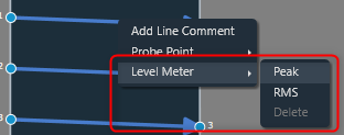
When the Peak option is selected from the context menu, a level meter will be added to the connection to display the connection’s peak output value.

When the RMS option is selected from the context menu, a level meter will be added to the connection to display the RMS value of the output in that connection.

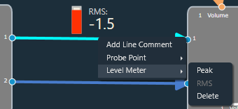
The color of the connection changes when a level meter is added. The color of the connection indicates whether a level meter is present in that connection. The level meter color will get updated dynamically based on the Peak/RMS value of the audio output.
The level meter control and value will not be shown if the device is not connected.
After adding Peak or RMS level meter, delete option will be enabled in context menu. Even the type of level meter can be switched by selecting the enabled level meter context menu option(Peak/RMS).
You can use delete option to remove level meter from a connection. On deleting level meter, level meter control and value will be disappeared, and connection color will reset to default.
Configuring Control Output connection
The Control output value of each control out connections can be viewed by adding level meters through context menu of the connection,

When the Add option is selected from the context menu, level meter will be added to the connection to show control output value of that connection.

In addition to the control output value, the pin label will be displayed. A tooltip for the pin label has been added in order to see longer pin labels.

The color of the connection changes when a level meter is added. The connection color indicates the presence of level meter in a connection.
If device is not connected, level meter control and value will not be displayed.
Once after adding level meter, delete option will be enabled in context menu.
You can use delete option to remove level meter from a connection. On deleting level meter, level meter control and value will be disappeared, and connection color will reset to default.

While configuring Level Meter in signal flow designer, you can Undo or Redo the Add, Delete and Switching Parameter (Peak/RMS) operations.
Keyboard Shortcuts
Keyboard shortcuts are available to add/delete level meters in signal flow designer screen. Following are the keyboard shortcuts available for different operations:
- Ctrl+Shift+P – To add Peak Level Meter
- Ctrl+Shift+R – To add RMS Level Meter
- Ctrl+Shift+A – To add Control Out Level Meter
- Ctrl+Shift+D – To delete Level Meter
Once one or more connections in the signal flow have been selected, the keyboard shortcuts can be used. This option makes it simple to add or remove multiple level meters.
Export and Import Level Meters
While exporting the project, the added level meters will be exported as part of GTTD file. On importing the project, exported level meters will be imported to GTT.
Delete all Level Meters
You can delete all level meters added in an instance by using “Delete All Level Meters” option in instance context menu. GTT will display a message after all level meters have been successfully deleted.

If no level meters are present, following error message will be displayed.

Level meter streaming will get stopped on disconnecting the device. On reconnecting the device, streaming will get resumed for existing level meters if SFD screen is active.
Level meters are not supported for below connections in V release:
– CAO output connections.
– Connections in CAO signal flow.
– Block control connections.
3.7.Copy and Paste Operation
The signal flow designer offers the handy capability of copy and paste, which can accelerate the design process.
Follow the below steps to perform copy and paste operation:
- On the signal flow designer, select an object to copy or press CTRL+A to copy the entire signal flow design.
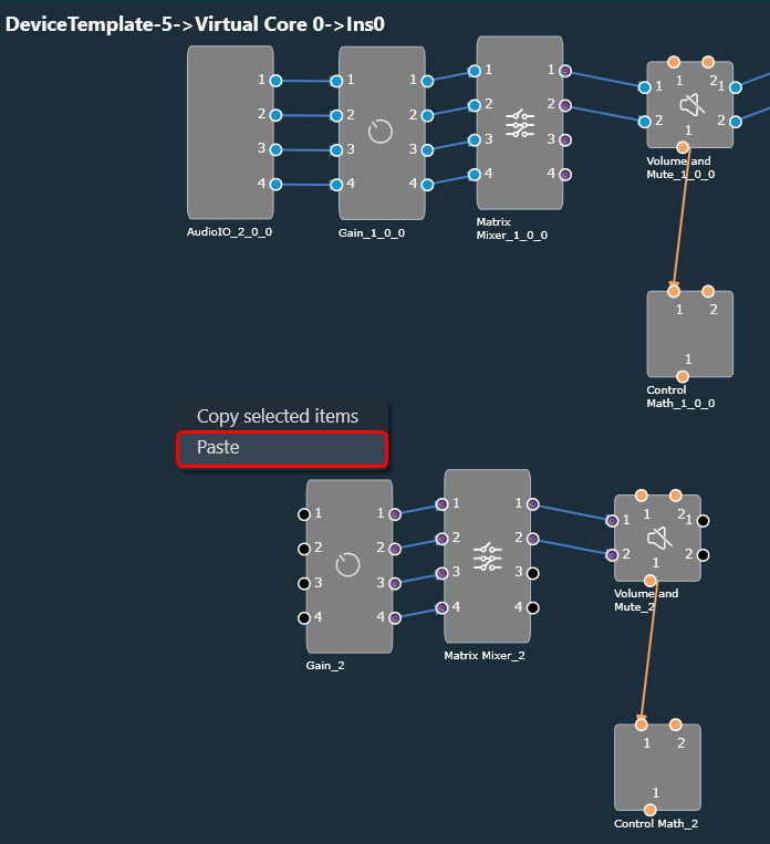
- Once the object or signal flow design is selected, you can either press CTRL+C or right-click on the designer area and choose “Copy selected objects” from the context menu.

- After the object or signal flow design is copied, you can paste it into the same or a different framework instance by pressing CTRL+V or by selecting the “Paste” context menu item.
3.8.Undo and Redo Operation
The undo and redo feature allows you to reverse or redo previous actions.
- Undo: The undo feature allows you to reverse the previous action by restoring the design state to a previous design state.
- Redo: The redo feature allows you to perform the action that is undone.

Undo and redo feature is not available in the tuning flow view.
Undo/Redo operation is supported for the following actions:
- Add/Remove of audio objects.
- Add/Remove of audio object connections Audio object movements.
- Audio object property changes.
- Additional parameter, additional parameter config changes Pin label, connection label changes.
- Copy/Paste of audio objects.
- Audio object processing state actions.
- Extract CAO.
The scope of Undo/redo will be within the specific instance.
In some cases, a toast message appears to help invisible items getting undone or re-done.
- Additional parameter config panel changes.
- When processing state cannot be applied.
This feature is limited to 1000 actions.
When a new manual action is performed, Redo stack will be cleared.
3.9.Block Control
This feature enables signal flow designer to group multiple control signals into a block control.
Audio objects needed or block control signal to control signal conversion and vice-versa.
- Control Grouper: Facilitates SFD user to group the control signals into block control.
- Control Splitter: Facilitate SFD user to split the individual control signals.
Any audio object which supports block control should declare a flag in dynamic metadata as below.

The block control connections are highlighted as thick lines in both SFD and CAO signal flows.
Block control pins are in dark orange color and on connection mouse hover block pin details are displayed.

It is possible to make block connections only when the group count matches. Else a validation error will be thrown.
If the group count is 1, it is possible to connect normal control pin with block control pin.
3.10.Signal Flow Design Validation
DDF Template Validation
In case there are issues with the DDF file generated by the toolbox during creating a device or modifying of the signal flow, an error notification will be displayed. GTT will recognize any audio object that is incomplete or has failed as corrupt.
It is recommended that you should fix the DDF template of the affected audio object and proceed with your work.
- If you import or open a project that contains a corrupted audio object, a warning message will be displayed.

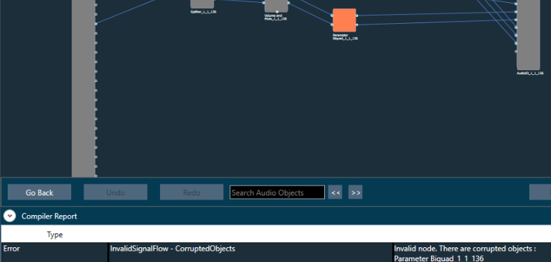
On opening the signal flow which has corrupted object, the corrupted audio object will be highlighted as shown below, and the same will be displayed in the compiler error window.
- If the signal flow has corrupted objects on sending or exporting signal flow, the following message will be displayed.

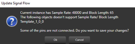
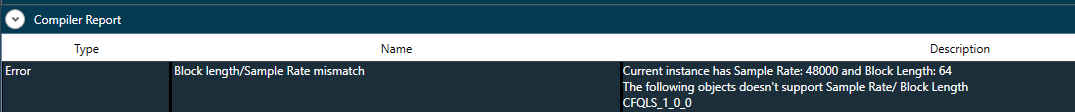
- If there is a mismatch between Sample Rate/ Block Length of instance signal flow and current audio object in the toolbox, then a warning message pops up and the corresponding object will be disabled in the toolbox.
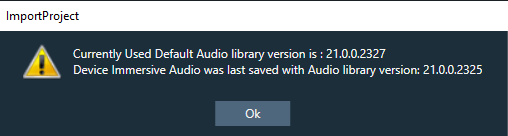
- If there is a version mismatch between the current audio library version and the version data on the device, a warning message appears asking whether to continue or stop saving.
- If there is a tuning version mismatch between audio objects in the signal flow and audio objects in the toolbox, a warning message will be displayed, showing the tuning version differences, and those audio objects are highlighted in blue.
- If the Sample Rate/Block Length does not match, a message will be displayed asking if you want to continue or stop saving.
Additional Parameters Validation
The GTT will perform validation of input data in the additional parameters window, based on the information provided by the xAF dll for specific audio objects.
The below validations are added on xAF and GTT.
- ASCENDING
- DESCENDING
- NOTEQUAL
- EVEN
- ODD
- EVEN_ASCENDING
- EVEN_DESCENDING
- ODD_ASCENDING
- ODD_DESCENDING
The below figure displays the value entered should be an odd value. An error message is displayed to when an even value is entered.

3.11.Securing Audio Objects
Using “Lock\Unlock” functionality you can secure audio objects. This will help you to safeguard Harman proprietary audio objects during collaboration. This feature encrypts Harman audio objects within the project, preventing unauthorized access by third parties. Additionally, you can hide the tuning data, ensuring sensitive information remains confidential when sharing the projects.
Characteristics of secured audio object:
- Secure audio objects will not allow any of their properties to be edited. The Properties window will be disabled.
- New secure audio objects cannot be added to the signal flow.
- There is no way to remove, duplicate, or copy a secure audio objects.
- Upgrade of secure audio objects is not possible. Error message will be shown to use the valid framework dll.
- Native panel cannot be opened from the signal flow or custom panel.
- If any secure audio object has been configured in custom panel before locking, it will continue to work. However, after locking it is not possible to add secure audio object native panel to custom panel. Secure state variables will be disabled in address assignment window.
- Secure audio objects will be hidden in Sate Variables explorer, MIPS, Memory, Memory Latency, and Streaming window.
- It will not be possible to export the DDF of the device which contains secure audio objects.
- In the XTP viewer, secure audio object’s tuning will not be decoded.
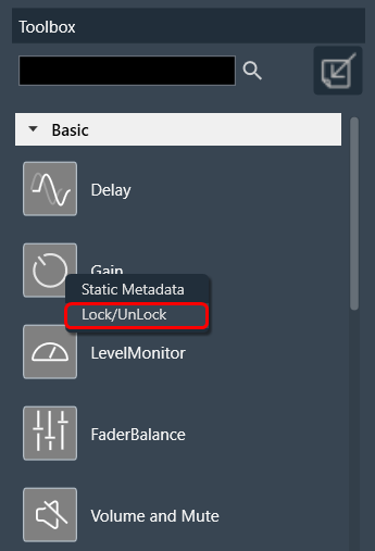
In the toolbox, you can use “Lock/UnLock” option available on right-click of any audio object to secure any audio object. Once the audio object type is locked (password protected), all the instances of that audio object type will be locked across all the projects. The locking of audio object feature is audio library specific.
Once the lock is applied to any audio object type, following changes will take place in the system.
- Locked audio objects are distinguishable from other audio objects with lock symbol.
- Lock is on all instances of the particular audio object type across all projects based on the selected audio library version.
- Audio object will be locked in CAO instances. However, CAO types are excluded.
- When “Open Signal Flow for Tuning” is clicked on the Instance, the audio objects will remain locked.
- Audio objects remain locked in CAO instance signal flow
- Undo and Redo history will be cleared from the Signal Flow Design.
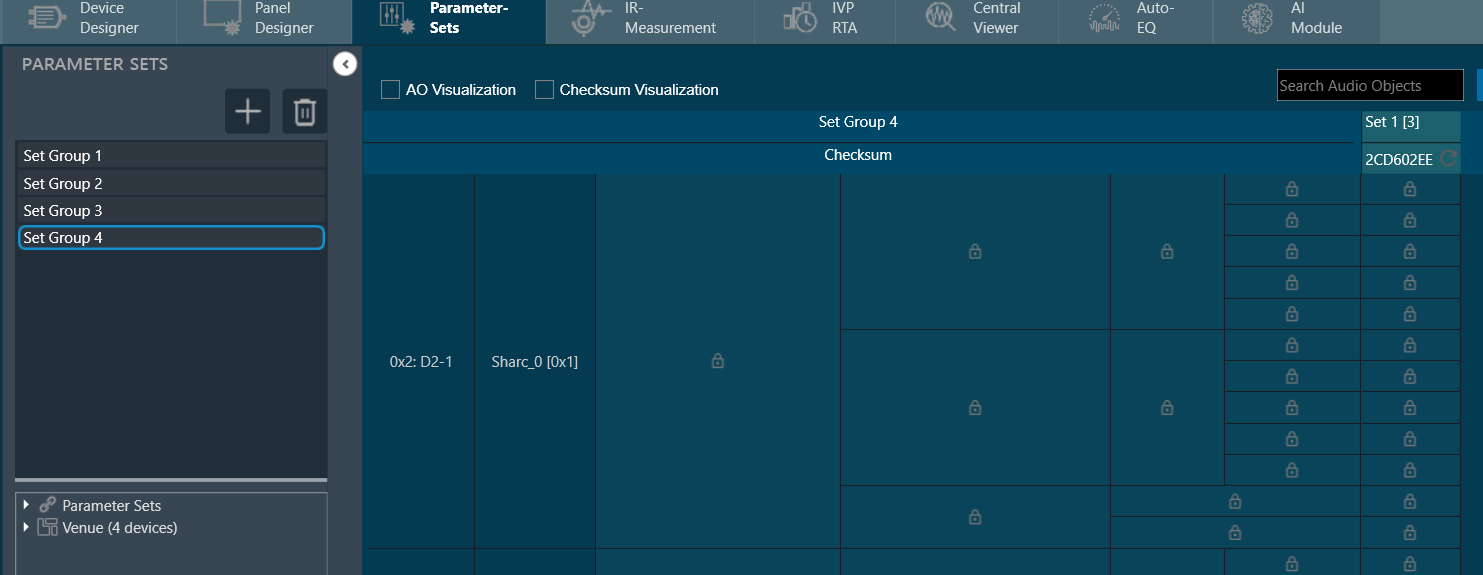
- In Parameter sets, Secure audio objects will be masked with the lock icon in the parameter sets window and presets cannot be changed.
- You can export .set and .setr files from presets and import it back. There will be no change in .set files. However secure audio objects will be excluded in .setr file as it is human readable. You cannot read the tuning data of secure audio objects in .setr files.
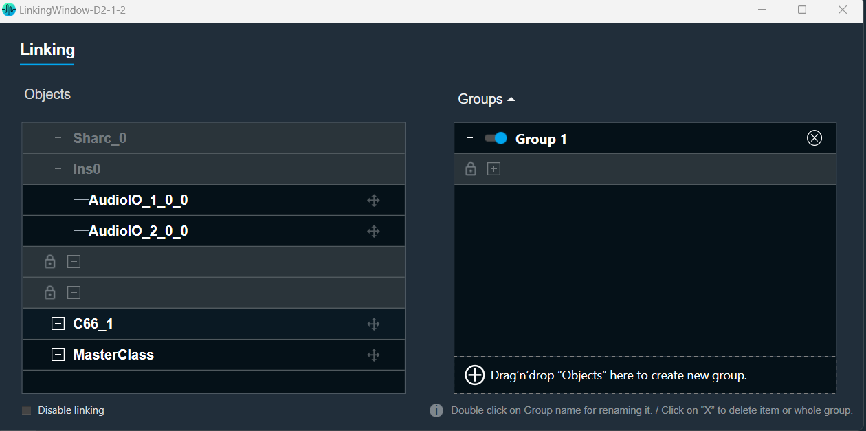
- If the audio object is locked, the secured audio objects will be masked with lock icon in linking window.
After locking the audio object it will be not be possible to add the secure audio objects for linking. The linking continues to function as intended.
- When you lock audio objects in a project, remember to also export the secure DLL before sharing the project with others. This DLL is required to use the locked audio objects.
On export of a project with secure audio object, a warning message will be displayed to export the secure dll from device designer.

- In the device designer, you can create a Xaf framework dll with the secure audio object information added to it.

- Exporting a secure DLL creates a copy of the specific audio framework version used in the project. This ensures compatibility between the project and the DLL.
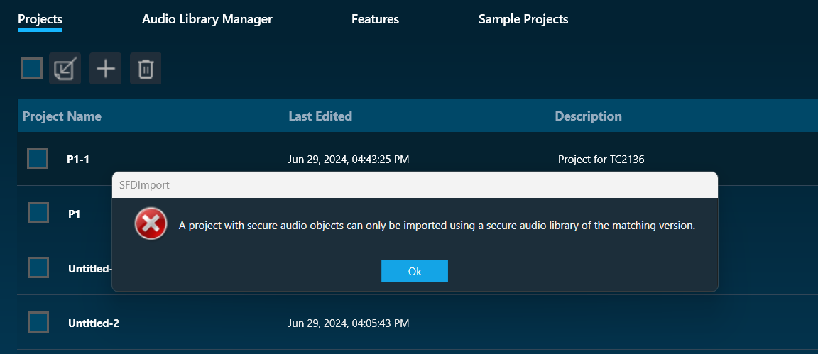
A project containing secure audio objects can only be imported if the corresponding secure DLL is available. This DLL provides the necessary security measures to access and use the locked audio objects.
If the project creator doesn’t export the secure DLL, the other user importing the project might need a password. This password would be required to unlock and use the secure audio objects.
Attempting to import a secure project with an incompatible or unsecured DLL will result in an error message. This message likely informs the other user that the project requires a specific secure DLL for proper functionality.
- The secure dll is same as any other Xaf dll. It can be used for Integrated Virtual Processing (IVP). Also, all file properties of the dll will be retained.
- During project export and import, all audio objects will retain their secure status, including any passwords set on them. When the project is closed or opened, it retains its secure status.
When exporting the project with secure DLLs, it is mandatory to export the secure DLL. If not, the user has to share the password with other user who wants to use the project.
CAO type cannot be secured in W release
4.Create a Signal Flow
Before creating a signal flow, it is necessary to complete the following configurations.
- Make sure you need to add a device to the project. For more information on how to create a project and add device to the project, refer Create a New Project.
- Once you have created the signal flow, the next steps involves tuning and analyzing the signal flow. To analyze the signal flow according to your specific requirements, you need to configure the analyzer settings. The analysis can be performed using the IVP RTA window. For more details on IVP RTA settings, refer Real Time Analyzer User Guide.
If you are running a virtual device select WIN32(legacy) or WIN64 (IVP and VST3).
Not matching core types will cause issues on your device (virtual and real).
Follow the below steps to create a signal flow design:
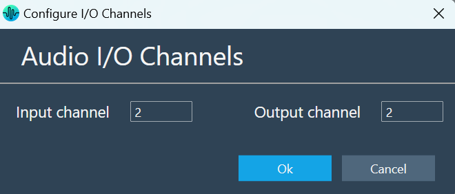
- On the Device View, drag and drop the Xaf Instance from the toolbox to the virtual core

This action opens the Configure I/O Channels message box. - Enter the Input channel and Output channel value and click OK. The audio objects inside the signal flow designer are filtered based on Data Format of the core.
- Select the Xaf Instance and configure the core object properties; Sample Rate and Block Length.
- Sample Rate: This sample rate will be applied to all the audio blocks in the signal flow
- Block Length: It is required internally by the xAF framework.

- Once you configured the Xaf Instance core object properties, click Save.
- Double-click on the Xaf Instance to open the Signal Flow Designer window.
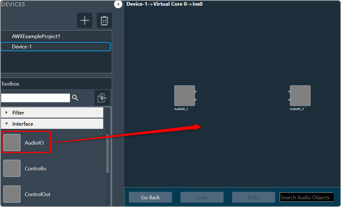
- On the Signal Flow Designer, go to the Toolbox section, expand Interface, and drag AudioIO audio object to the design canvas. Similarly add another AudioIO audio object to the design canvas.
When adding an xAF instance to a device that is already online, this AudioIO can be added. Thus, this step is only necessary if these two AudioIO objects are absent.
- Select one of the AudioIO audio object and set the Object Mode parameter to Audio In. Similarly, select another AudioIO audio object and set the Object Mode parameter to Audio Out.

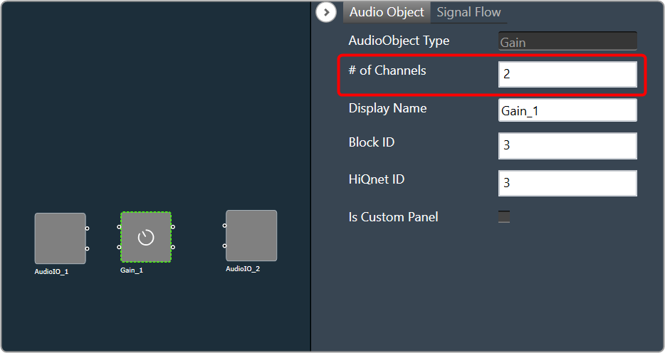
- Expand Basic and drag Gain audio object to the Signal Flow view. You can use any of the audio object, for example Gain audio object is used.
- Select the Gain audio object and set # of channels parameter to 2.
The number of channels determines the number of connectors that will be assigned to the AO. In GTT, you can allocate as many channels as required for your device.
- Press CTL+A or hold the CTRL key, to select an individual audio object from the Signal Flow view, and click Connect Blocks to connect all the audio object.
Or
You can connect the pin manually by establishing a connection between each pin of the AO.

Now you have an input and output object, as well as an object to tune gain, invert, and mute parameters for each channel of signal flow designer. - Click Save to save the signal flow design and click Go Back.
- Click on Send Signal Flow.
Before performing the “Send Signal Flow” operation, make sure that the IVP is properly configured.
A pop-up message will ask you to reboot device.

- Switch to IVP RTA tab and click Reboot.
- Switch to Device Designer tab and click on Connect Device to connect to device.

- Device synchronization dialogue box will appear, enable the desired synchronization option, and click Send.

If AmpSrv is unable to connect, close it and retry.
Now you can perform tuning on the IVP RTA.
A message “Signal flow successfully submitted” will be displayed. The Signal Flow will be sent to the virtual amplifier.
Using the Export option, you can export the signal flow design details. One .mcd file will be generated for master control data, and one .SFD file will be generated per instance per core.
5.Tune a Signal Flow
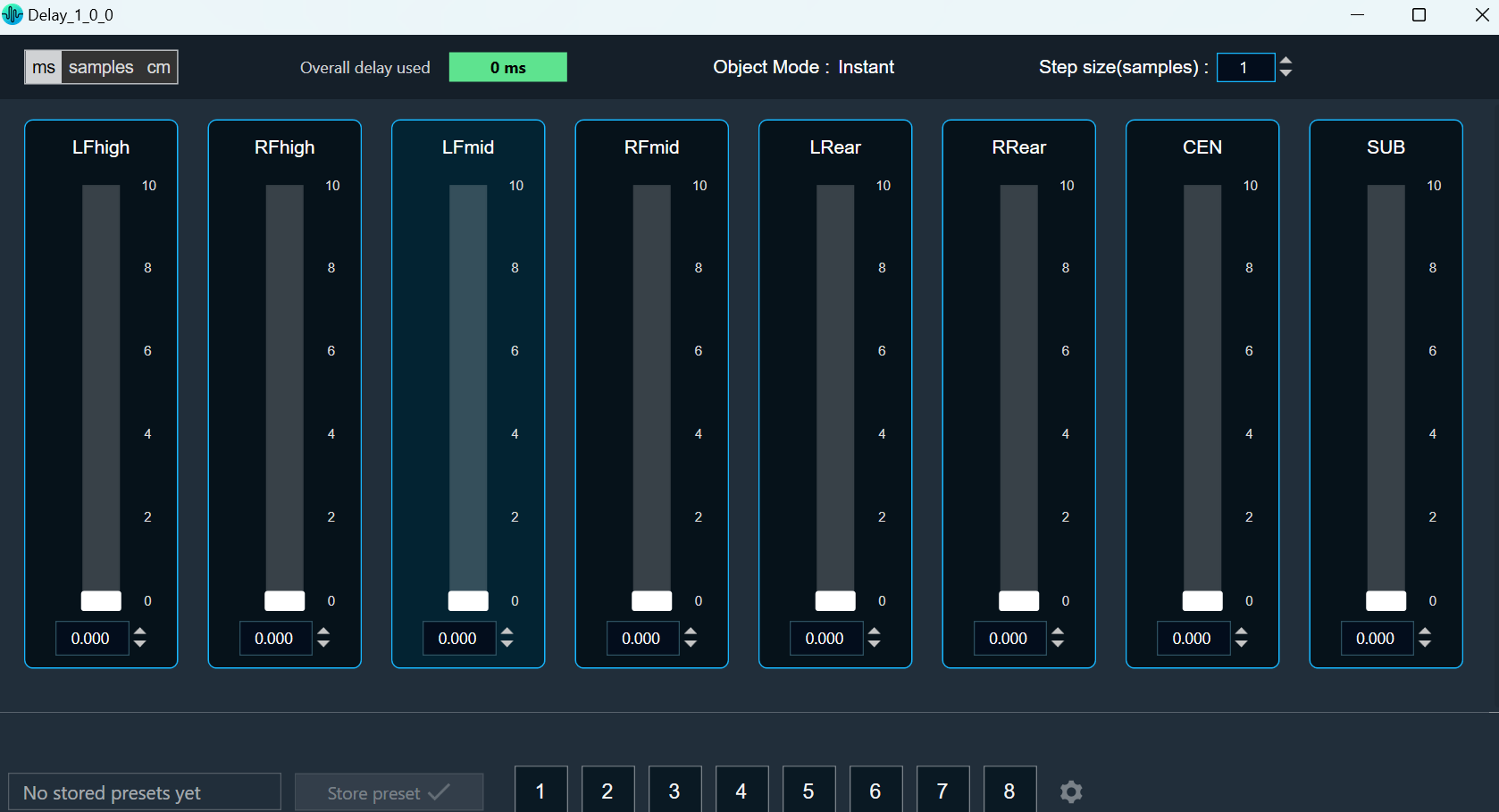
Native panel is one of the important element of the Signal Flow Designer. The native panel has interactive widgets that help to tune complex audio objects easily.
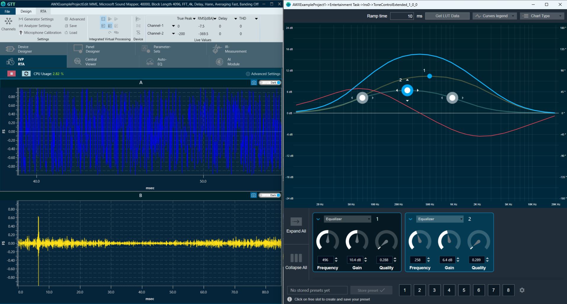
The tuning of a signal flow will be illustrated by showing the tuning effects on virtual devices in IVP RTA. RTA is a multi-channel Real Time Analyzer for audio signals. It provides time and frequency domain analysis tools to measure RMS/peak levels, frequencies, THD, delays, magnitude, and phase responses.
Launch Native Panel
- On the Signal Flow Designer window, double-click on any audio object to open a Native Panel.
Use the interactive widgets on the Native panel to make the desired changes to audio object properties.When Native Panels is open, if there is any modification to Signal Flow Designer, a popup message will appear asking to save the changes.
When Native Panels is open, you cannot make any changes to the Signal Flow Designer window. But you can open another native panel from the Signal Flow Designer window.
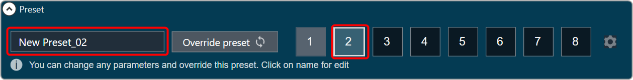
- If the preset bar is present in the panel, select the free preset slot numbers, enter the name of the slot, and click Store preset. This saves and stores the current tuning data to the selected slot.

If you do not enter a name of the slot, then it will take the default named “New Preset”.
You can switch between presets and apply their values to the native panel by simply clicking on them. You can also change the values in the native panel or the preset name after you have clicked it to override the preset.
You can reset the selected preset or all the preset.

- Click Reset Selected to clear the preset that is currently selected.
- Click Reset All to clear every preset in the corresponding native panel.
Visualize a Signal Flow
You can check the tuning effects of the designed audio signal flow on the virtual device in IVP.
For more information, refer to Analyzer and Generator.
Perform Tuning
The audio objects that do not have their own native panel can create a custom panel and link the panel with the respective audio object.
If an audio object doesn’t have its own native panel, you can create a custom panel and link it to the appropriate audio object under the “Available Custom Panels” option.

Follow the below steps to view the signal flow performance:
- Go to the IVP tab, start Generator, Analyzer, and Plugin Host.
For more details about Generator, Analyzer, and Plugin Host settings, refer to the Real Time Analyzer User Guide.

- Go to the Device Designer tab, click on Send Signal Flow to send tuning data.

- Open the native panel and go back to the IVP window.
- On the native panel, tune the signals. The signal flow in the IVP tab will change accordingly.

6.Native Panels
The Native Panel is a user interface which contains graphical element or component that allows you to interact with various parameters of audio object and allows you to easily tune complex audio object.
These panels can provide options to adjust settings, routing audio signals, applying effects, and more.

Below is a list of audio objects that support native panels.
6.1.Launching Native Panel
To launch a native panel from the Signal Flow Designer, it is assumed that you have already created a signal flow. For more information on how to create a signal flow, refer to Create a Signal Flow.
Steps to launch Native Panel from Signal Flow Designer
- On the Signal Flow Designer window, double-click on any audio object to open a Native Panel.
Use the interactive widgets on the Native panel to make the desired changes to audio object properties.
If there is any modification to Signal Flow Designer, a popup message will appear asking to save the changes.
When Native Panels is open, you cannot make any changes to the Signal Flow Designer window.
- Select the free preset slot numbers, enter the name of the slot, and click Store preset. This saves and stores the current tuning data to the selected slot.

If you do not enter a name of the slot, then it will take the default named “New Preset”.
You can switch between presets and apply their values to the native panel by simply clicking on them. You can also change the values in the native panel and/or the preset name after you’ve clicked it to override the preset.
6.2.Common Operation in Native Panel
Passing pin labels to native panels
The native panels display the corresponding names of the pin labels assigned to an audio object in SFD, thereby ensuring visibility.
This feature applies to the listed native panels.
- Delay
- Gain
- EQ/Biquad
- FIR, FIRMIMO, FastConv
- Limiter
- Mixer
- Router
On the Router panel first three characters of the out-pin labels will be displayed as a channel out names.
Look-up Table (LUT) panel has a separate mechanism to change the names of the channel.
Editing labels in native panels
You can modify Native panels pin labels. Double-click on a label, a text box will appear, enter the new name. The provided name will be updated both on the panel itself and on the corresponding pin in SFD.
For audio objects that have a configurable number of channels, the new value will be set for both the input and output pins. However, for other audio objects, the value will be updated separately for the input and output pins.
Depending on the panel, the displayed text may be trimmed if it exceeds the available space. This feature applies to all native panels except for the Biquad panel and the LUT panel.
Resizing Native Panel
When the native panel window is resized, the controls are resized to fit the window.
Following are the native panel which support resizing:
- Parameter Biquad,
- Crossover Biquad and
- Tone Control Extended Panels
Native Panel Presets
Preset or Tuning sets can be used to store the tuning data set of the native panel. This control is available in every Native panel.

Creating a Preset
Follow the below steps to create a preset:
- On the native panel, tune audio objects signal flow.
- Select a free preset slot (numbers), enter a slot name in the text box.
If you do not enter a preset name, it will take the default name of the New Preset.
- Click on Store Preset to save and store the preset.
The preset will be stored in the slot you had chosen. The blue color indicates that the preset is applied to the respective native panel.
You can create several presets and switch between them to apply their values to the native panel by simply clicking on them. Once they are clicked, you can also override the preset by changing the tuning data of inner audio objects or the preset name.
Resetting the Presets
Follow the below steps reset a preset:
- On the Preset section, select the slots, and then click on the settings icon.

- Click on Reset Selected to reset the selected preset slots.
If you want to reset all presets of the respective native panel, click Reset All.
6.3.Configuring Custom Native Panels
To launch a native panel, a device must be added to the device list.
Steps to launch Native Panel:
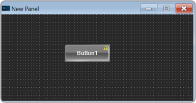
- Create a new panel. For more information on how to create a panel, refer to the Create a New Panel.
- On the panel, add Button from the Basic controls tools.
- Select the Button to open the Properties view, and select the System Function tab.
- On the System Function tab, click on System Functions. This opens System Function Editor window.

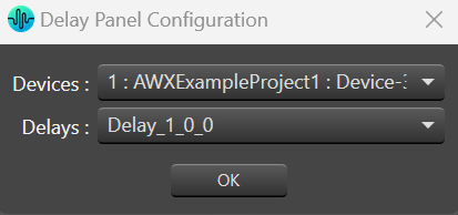
- On the System Function Editor window, select the Function as Launch Native Panel from the drop-down list, and select the native panel type from the drop-down list. This opens a Configuration panel.

- On Configuration panel, select the device/project and audio object from the drop-down list which you want link, and click OK.
Depending on the selection of device/project the list of audio objects is displayed in the drop-down list.
If you want you can customize the Button appearance. - Go the Properties view, select the Button tab, and change the button name, font style, text colour, fill colour, and border colour.

- Click on Launch Current option from ribbon bar and click on button to open Native Panel.
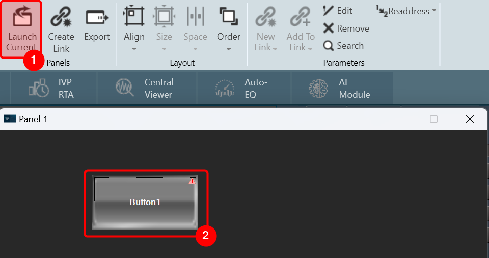
On the Native panel you can make the desire changes and store the changes.
- This feature helps you to set processing state when you doesn’t have license to SFD.
7.Additional Audio Block Configuration Parameters
Audio Objects may require a different set of configuration properties than the default ones like # of channels, audio inputs, audio outputs, and number of elements. In such cases, it is possible to customize the configuration properties of the AO to better match the specific requirements of the device.
The LUT audio object serves as a suitable example; you need to define the number of rows and columns in the table. To facilitate this requirement, additional configuration parameters are added in both GTT and xAF.

Theoretically, an audio block can have any number of additional configuration parameters. These parameter definitions are obtained from the xAF library in conjunction with the parent block definition. The parameter definition consists of parameter order, name, and value, which are currently represented as floats. There are plans to enhance parameter definitions in the future to accommodate multiple parameter types.
When a metadata is available, the additional parameters are displayed as shown below.

On the Audio Object Property view, click on the Configure. The system will open an additional parameters window, where you can provide additional parameters. These additional parameters are of the same data type which is provided as part of parameters definition.

After making the necessary modifications, click the Apply and the system will implement the designated supplementary parameters.
Dynamic Additional Parameters
This feature is to change the size of additional parameters based on IO modifications. This feature is available for selected Audio objects which have “isAddVarUpdateRequired” flag set in their static metadata.

8.Harman Audio Library Service
The Harman Audio Library Service (HAL) service is a wrapper around the xAFVirtualAmp library. It’s been created mainly because GTT is a 64-bit application, while xAFVirtualAmp is a 32-bit library, hence it is not possible to launch both binaries in the address space of the same process. In addition, GTT also supports 64-bit xAFVirtualAmp from “R Release”.
Internally, the HAL service is implemented as a WCF service hosted in a Windows service. It communicates with GTT via named pipes.
The Harman Audio Library Service exposes the following xAF API to GTT.
- getAudioToolboxBuffer: Returns the AudioToolbox.xml file as a string. AudioToolbox.xml contains definitions of audio blocks known to a particular version of the xAFVirtualAmp library.
- getIoObjectInformation: This method accepts audio block configuration parameters and returns the IO layout of the block (# audio ins, # audio outs, # control ins and # of control outs).
- getTuningInformationBuffer: Returns a device description snippet for an audio block. Iterative invocation of that method for each audio block across all framework instances produces a device description file.
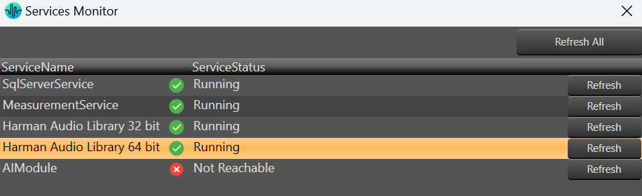
After a successful installation of GTT, the HAL service should be automatically initiated by default.
In case the service is not operational or has been deactivated for any reason, the GTT will notify you of such situations through error messages.
To activate the HAL services:
- Open GTT project window, click on Service Monitor. This opens service monitor window.

- On the Service Monitor window, click Refresh for Harman Audio Library.
9.Support for Multiple Framework Instances
The xAF framework is designed to support a single core and a single instance running on that core as its default setting. However, it is possible to create a personalized xAFVirtualAmp version that supports multiple framework instances to be distributed over several cores.
Currently, the audio routing between cores at the device level and between instances at the core level is hardcoded. In the future, it will be possible to provide the routing configuration using GTT.
For now, the tool makes it possible to build signal flows consisting of multiple cores and framework instances, as well as to generate device descriptions for such setups. However, when creating a multi-core, multi-instance arrangement, it is necessary to have prior knowledge of the audio routing hardcoded in the xAFVirtualAmp library and adhere to its limitations.
Once the design is done, you can send a complete configuration (control configuration for a device and signal flow configurations for each framework instance) to a real or virtual device.
After completing the design, it is possible to send a complete configuration (including control configuration for a device and signal flow configurations for each framework instance) to a physical or virtual device.
To send configuration to a physical or virtual device:
- On the Device Designer view, click on Send Signal Flow.

10.Feedback loop in Signal Flow
GTT does not support feedback connection in signal flow.
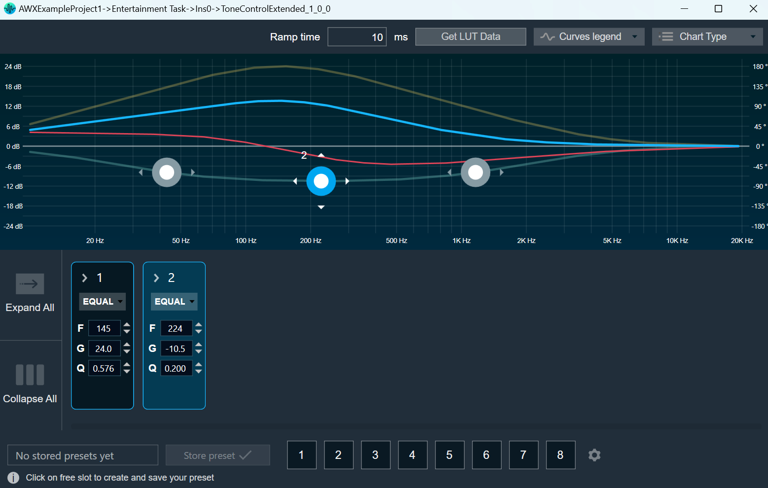
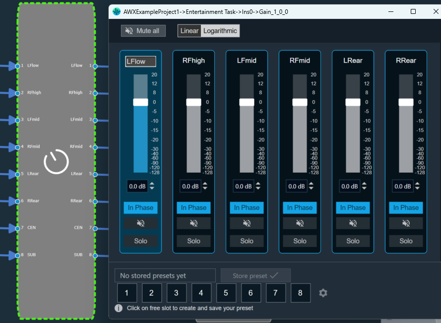
In the below example, it is not possible to connect “Gain_1_0_0” to ToneControlExtended_1_0_0” in Signal Flow, as this connection leads to loop.

Hence if you try to connect any audio objects which will lead to a loop, a notification is shown that “Connection is not possible”.
For a legacy project.
If a signal flow already has a feedback loop, the designer will indicate this and an error with the compiler will be reported. In order to save the signal flow, you must first remove any existing loops.
There is no restriction to add loops in control signals.

11.Compound Audio Object
The Global Tuning Tool allows you to combine audio objects into a single large component that can be reused. This is known as a compound audio object.
By grouping audio objects into CAO, designers can keep their signal flow elegant. Complex reusable audio objects and their connections can be saved as CAOs, allowing for faster signal flow generation when using these CAOs.
CAO stands for Compound Audio Objects.
Device will not know anything about Compound Audio Object. When the user sends signal flow to the device, GTT will scan the signal flow and replace Compound Audio Objects with the inner basic objects. It will establish all the connections so that when the signal flow reaches the device, it is expanded. This will ensure no further implementation is needed on the device to process CAO.
GTT has the ability to identify the author of a CAO, which will be provided to access the features such as editing and exporting. The compound audio object also allows for versioning, enabling authors to keep track of the different versions of CAOs they have created. GTT can validate the version of the CAO used in the signal flow.
It is carefully considered to bundle them in a project file (.gttd), so that CAO present in the signal flow can be exported and imported. GTT provides the majority of the existing CAO interfaces, so you will have no difficulty learning to create CAO.
11.1.Create a Compound Audio Object
Creating a Compound Audio Object is very simple. The designer has to select an audio object from an existing signal flow and extract audio objects into a Compound Audio Object. The application will replace the extracted audio objects with the Compound Audio Object in the signal flow.
To create Compound Audio Object:
- Open a project and go to Signal Flow Designer window.
- Select the audio objects in the Signal Flow Designer window and click on Extract. This opens the Compound Audio Object window.
Extract can be performed only when valid audio objects are selected. Currently, the GTT Version does not support FIR MIMO, EOC, RNC, Audio IO, Control IN, and Compound Audio Object extraction.
Extract functionality will be enabled only if Signal Flow is saved.
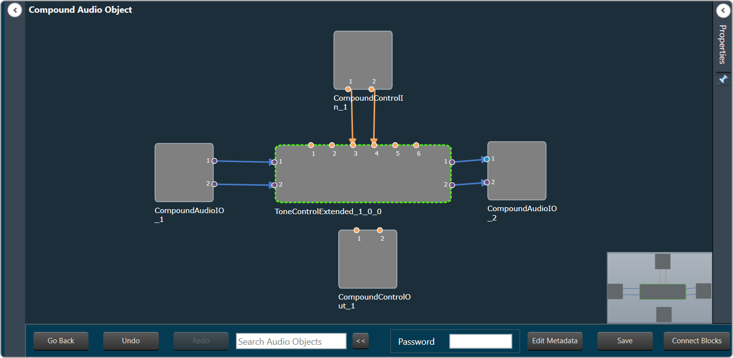
On Compound Audio Object window the selected audio objects are surrounded with the interface objects like AudioIO and Control IO.
The interface objects are used to configure Compound Audio Object’s pins (AudioIO, ControlIO). Also, you can tune inner audio objects just like basic audio objects.
- Click Save and enter the Compound audio object Name and Description.
- Select a free preset slot number, enter a name in the text box and then click on Store preset to save and store the preset.
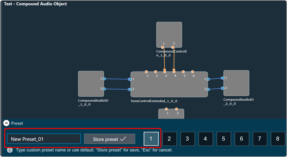
The preset will be stored in the slot you had chosen. The blue color indicates that the preset is applied to CAO inner audio objects.
- Click Go Back after creating the Compound Audio Object.In the Signal Flow Designer window, you will see that the selected audio object has been replaced with the new compound audio object and the same audio object is listed under the Compound Audio Object category in the Toolbox.

Block Id cannot be assigned for Compound Audio Object instances.
11.2.Rename a Compound Audio Object
Once you added a Compound Audio Object in the Toolbox. You can rename the Compound Audio Object as per requirement.
To rename Compound Audio Object:
- Go to the Toolbox in Signal flow designer window, select the compound audio object under the Compound Audio Object category, and click Rename from the context menu.

- On the textbox, enter the desired name of the compound audio object, and click .
 Ok
Ok
A successful message will appear after the modifications have been made.
CAO renamed will update CAO type name in all devices and projects.

11.3.Export a Compound Audio Object
It is very convenient to share the Compound Audio Object by exporting it to a .cao file. Compound audio objects are just like any other audio object in the Signal Flow Designer toolbox. Except that they are complex and not part of the audio library.
To Export Compound Audio Object
- On the Signal Flow Designer window, select the compound audio object under the Compound Audio Object category in the toolbox and click Export through the context menu.
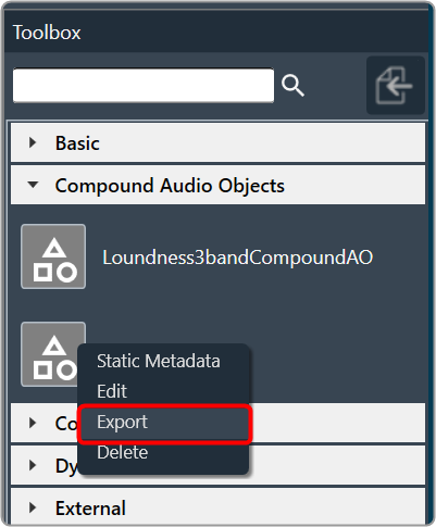
- On the dialog box, click Ok to export the Compound Audio Object.
- If the “Editable on import“ option is checked, it means you can edit the Compound Audio Object on import.
- If you uncheck the “Editable on import“ option, a new Compound Audio Object will be created while editing the Compound Audio Object on import.

- Navigate the location, and click Save the Compound Audio Object. The exported file is saved in .CAO format.
11.4.Import a Compound Audio Object
To Import Compound Audio Object
- On the Signal Flow Designer window, click on the Import Compound Audio Object option.

- Browse the location of Compound Audio Object and click Open. The imported Compound Audio Object added in the toolbox.
If the same Compound Audio Object is already in the toolbox, you can overwrite it or import it as a new Compound Audio Object.
The Compound Audio Object in the Toolbox can be dragged and dropped into the Device Signal Flow, just like a basic audio object.
If device signal flow is designed with Compound Audio Objects, it is carefully considered to bundle them in a project file (.gttd).

11.5.Tuning and Editing Compound Audio Object
Once you have created a compound audio object. You can perform the following actions on the compound audio object.
11.5.1.Edit a Compound Audio Object
To edit a Compound Audio Object:
- On the Signal Flow Designer window, select the compound audio object under the Compound Audio Object category in the toolbox and click Edit through the context menu. This opens Compound Audio Object editor.

- On the Compound Audio Object editor, modify the configuration and tune the inner audio objects.

- Click Save, once the modifications are done.
The compound audio object or tuning version is automatically incremented when you close the Compound Audio Object editor window. Tuning major version auto increment happens for the below scenarios.- When an audio object is added or deleted.
- When the inner connection changes.
- When there is a change in the audio object configurations inside Compound Audio Object.
- When the Object mode/ Additional parameters changes.
- When an audio object channel numbers are modified.
- When an audio object is upgraded.
- When the inner Audio object tuning data is modified.
- Close Compound Audio Object editor window to redirect to Device Signal Flow.
If the Compound Audio Object version is changed, the Compound Audio Object in the Device Signal Flow will be highlighted in a different color and must be upgraded in order to save signal flow.
Right-click on the highlighted audio object and select upgraded audio object from the context menu.
On major version upgrade of CAO, tuning data will be set to default tuning data of CAO template in toolbox.
Compound Audio Object can be edited without affecting the current working Device Signal flow. This means that you can edit Compound Audio Object while connected to a device. It will not interfere with the current device configuration.
Using the Ribbon Button under the Signal Flow Designer tab, you can view the State Variable Explorer for the currently designed signal flow. The title of the State Variable Explorer window will be “CAOTemp_(CAOName).”
The CAO name is “Loundness3bandCompoundAO” in the image below. The “CAOTemp_” is the suffix that denotes a temporary explorer for CAO editing.

11.5.2.Edit Compound Audio Object Meta Data
The Compound Audio Object meta data could be updated by clicking Edit Metadata in Compound Audio Object view.
To Edit the Compound Audio Object Meta data:
- On the Signal Flow Designer window, select the compound audio object under the Compound Audio Object category in the toolbox and click Edit through the context menu. This opens Compound Audio Object edit view.
- On the Compound Audio Object editor, click Edit Metadata. This opens the Update Static Metadata dialog box.

- Edit the Compound Audio Object Version or Tuning Version.

- Click Apply to update the changes.
During creation, the Compound Audio Object version and the Tuning version are set to 01.00.0 and 01.00 respectively.
When editing, you have the option to update the version of the Compound Audio Object or Tuning Version based on your needs, and this information will be recorded by GTT.
Auto increment always works with the latest version available before Save. This means, if the user edits the version before saving, the user updated version will be auto incremented based on the above criteria.
11.5.3.Create Preset for Compound Audio Object
Preset or Tuning sets can be used to store the tuning data set of a CAO template signal flow. These stored tuning sets can be applied on instances of CAO template.

Preset control feature is available for all saved CAO templates. It can be used to store the tuning data set of CAO template.
To create Preset
- On the Compound Audio Object editor, tune audio objects signal flow.
- Select a free preset slot (numbers), enter a slot name in the text box.
- Click on Store Preset to save and store the preset. The preset will be stored in the slot you had chosen. The blue color indicates that the preset is applied to CAO inner audio objects.

You can create several presets and switch between them to apply their values to the CAO template by simply clicking on them. Once they are clicked, you can also override the preset by changing the tuning data of inner audio objects or the preset name.
Only after Compound Audio Object is saved, the Preset control feature will be available for configuration.
If you do not enter a preset name, it will take the default name of the New Preset.
Set presets are available for application, only on exiting Compound Audio Object editor view.
Reset Presets
To Reset Presets
- On the Preset section, select the slots, and then click on the settings icon.

- Click on Reset Selected to reset the selected preset slots.
If you want to reset all presets of the respective native panel, click Reset All.
Apply Presets on CAO Instances
If presets are available in CAO templates, you can apply these presets to CAO instances in the main signal flow.

- On the Signal Flow Designer window, right-click on compound audio object instance, go to Apply preset tuning data, and then select the required presets displayed in sub-menu.
- Click Ok to apply the tuning data of a preset to all inner audio-objects of the selected compound audio object. After applying the tuning data a successful message will be displayed.

Apply preset tuning data option will be available only when signal-flow is in saved state.
Presets will be exported/imported along with a Compound audio object template.
11.5.4.Set password for Compound Audio Object
Adding a password to a compound audio object (CAO) can ensure its security. During the creation or modification of a CAO, it is possible to add a password, although this step is not mandatory.
It is important to remember the password in order to access and view the signal flow of the Compound Audio Object (CAO).

To enhance the security of the CAO, it is advisable to periodically change the password at specific intervals. This measure can help prevent unauthorized access and ensure the continued protection of the CAO. The signal flow should be saved after entering or updating the password.
Click on the edit CAO option to view the signal flow. If the CAO contains a password, an authentication dialog box will be displayed. Enter the valid password to view the CAO Signal flow.

11.5.5.Edit Compound Audio Object Instance
You can view or modify the Compound Audio Object instance using the “Open Signal Flow” option. The Open Signal Flow option enables to view signal flow of CAO instance that is added to Main Signal flow. The view allows you to customize and save the Block Id and Display names of inner audio objects in CAO instances.
Steps to open CAO instance signal flow:
- On the Signal Flow Designer window, right-click on CAO instance, and select Open Signal Flow option.

When the Compound Audio Object version is updated, it will be highlighted in a different color in the Signal Flow Designer. In order to save the signal flow, the upgraded Compound Audio Object.
Navigation to CAO instance Signal-flow will be allowed only if password validation is successful for password protected CAO templates and if CAO template is editable.
- On the CAO instance signal-flow window, select the respective audio object and edit the Display Name and Block Id, if required.
Except for Display Name and Block Id, all audio object properties on the CAO instance signal-flow window are fixed.
Customized Display name /Block ID will be assigned only if it is unique across Main signal-flow.
Block Id cannot be assigned for Compound Interface objects – Compound Audio IO , Compound Control In, Compound Control Out.

- Click Save to save all updated Display Names and Block Ids.
- Double-click on audio objects to open the native panel (if available). The native panel allows to tune audio objects. Audio objects can be tuned for CAO instance without additional custom panel creation.
- Once you made all the changes in the CAO instance signal-flow window. Click Go Back to navigate to the primary Signal Flow Designer window.
Customized Display Name and Block Id will be updated in all device associated data, making it identifiable in DDF/State Variable Explorer/ Venue Explorer/ Custom Panel address editor.

11.5.6.Apply tuning to Compound Audio Object Template
Tuning a Compound audio object (CAO) in Signal flow can be performed live by connecting to the device. CAO inner audio objects can be tuned using custom panels, the state variable explorer, or set files.
By clicking Apply tuning data to Toolbox type, CAO instance tuning can be applied to CAO template in toolbox.

11.6.Tuning Panel Compound Audio Object
Compound audio objects are created by extracting audio objects from the signal flow. When the CAO is exported, both the compound audio object and the panel associated with it can be shared with others, and it is simple to tune when the CAO is imported. This section explains how to link a custom panel to CAO.
To link custom panel with Compound audio object:
- Open the GTT and create a Compound Audio Object. To create a Compound Audio Object follow the steps mentioned in the Create a Compound Audio Object section.
- Once Compound Audio Object is created, go to the Panel Designer tab to create a custom panel. To create custom panel, refer Create a Custom Panel in GTT section.
- Once the custom panel is created, go to the Signal Flow designer window and select the Compound Audio Object. This opens the property of the Compound Audio Object.
- On the Compound Audio Object property, check the Is Custom Panel option and select the appropriate custom panel from the list box.

- Double-click on the Compound Audio Object to launch the custom panel.

There will be exclamation marks on the control if the state variables are not associated with the control. All exclamation marks must be fixed before proceeding further.
Refer to Create a Custom Panel in GTT to link state variables to controls. - Once the custom panel is verified, go to the Compound Audio Object property, and click on Link Custom Panel to CAO in Toolbox.

- Click Ok to confirm. Now the custom panel is linked with the toolbox type.
This option will be available only if the audio object selected is a CAO type.
Sharing Compound Audio Object
Once the custom panel is linked with the CAO, you can verify the link by dragging the CAO into the signal flow and double-clicking it. The panel should launch like any other audio object with default panels.
To share the compound audio object with others, export it as a .cao file, refer to Export a Compound Audio Object section.
If the .cao file contains a custom panel, it will be associated with the panel when the CAO is imported. CAO can be launched and tuned by dragging it into the signal flow designer and double-clicking it.
Editing Compound Audio Object
In addition, it is possible to make changes to CAO files that have exported as .cao files.
To include the CAO Instance panel to the list:
- Go to the Compound Audio Object property, and click on the Add CAO Instance Panel to the list.
This will open up the edit custom panel window where you can make further modifications.

The edit option for “Add CAO Instance Panel to the list” feature will be available only for CAO type only.
11.7.Multi dll support for CAO
The Compound Audio Object template can be shared across multiple audio library versions. Only the Compound Audio Objects associated with the current device version will be available under the Compound Audio Objects section of the Audio Object Toolbox.
- Add new CAO to Toolbox: In Signal flow Designer, extract an audio object. To know more, refer to Create a Compound Audio Object.
Newly created CAO will be added to Toolbox corresponding to device audio library version. - Add imported CAO to Toolbox: In Signal flow Designer, import a compound audio object. To know more, refer to Import a Compound Audio Object.
Imported CAO will be added to Toolbox corresponding to device audio library version. - Port to different audio library version
-
- Create a project with a device for which CAO is existing. Add CAO instance in Signal-flow.
- Close Signal Flow Designer window, go to Device Designer, and change the device Audio Library Version to target dll version.
- Open Signal Flow Designer window, CAO template will be added to toolbox for target dll version.
If inner audio object incompatibilities are detected, delete CAO in Signal-flow > Edit CAO template and upgrade incompatible inner audio objects.
Ported CAOs remain mutually exclusive. Edit/Delete on CAO template in one dll version will not impact CAO template in a different dll version toolbox.
11.8.Delete a Compound Audio Object (CAO)
To delete a Compound Audio Object, select the Compound Audio Object in the toolbox, and click Delete.

If the Compound Audio Object is used in any project, then it cannot be deleted.