
1.Terms and Abbreviations
| Abbreviations | Meaning |
|---|---|
| GTT | Global Tuning Tool |
| xAF | Extendable Audio Framework |
| VST | Virtual Studio Technology |
| RNC | Road Noise Cancellation |
2.Introduction
2.1.Purpose of the Document
GTT is a customized branch of AudioArchitect from Harman’s Professional Division. RNC is an advanced Audio
Object available in the Audio Algorithm Toolbox and supported by GTT.
This user guide will give you an overview on how to open RNC panel and what actions can be performed. For
general information on how to use GTT, please refer to the Global Tuning Tool User Guide.
3.Panel description
RNC panel
RNC object is using extended addressing logic, that means Block ID must be set in range 33024 – 65280. RNC panel allows the user to set multiple parameters (tuning and state parameters) for audio object and start different measurements. Panel can be opened as every native panel by clicking on RNC object in SFD Tuning Mode.
Panel consist of four main views:
- RNC
- Farina
- Misc
- AA Filters
3.1.Supported Modes
RNC object has two modes: RNC and Farina. Value for mode is updated when user switches the tabs on the top of the main view. Third tab (‘Misc’) is used to store configuration data for both modes. Switching tab into ‘Misc’ does not update audio object mode. Fourth tab (‘AA Filters’) allows user to set filter coefficients for three sets, observe filters sets characteristic on appropriate graphs and check if coefficients on the filter set are stable. Switching tab into ‘AA Filters’ does not update audio object mode.
3.2.SFD configurable parameters
Some of the object parameters are configurable through SFD.
| Name | Description |
| Number of accelerometers | Defines the number of accelerometers (range 10-12) |
| Number of microphones | Defines the number of microphones (range 4-8) |
| Number of virtual microphones | Defines the number of virtual microphones (range 4-8) |
| Accels offset calib. enabled | Enables/disables launching accelerometer calibration, when it is set to disabled Accelerometer tab is hidden |
| Virtual mic support enabled |
Enables/disables support for virtual microphones. When it is set to enable: · Top table in RNC mode will display a row for Virtual Microphones Gain · Path_P, Path_V, Path_PV, Path_PV_Measurement, Vir_Mic_gain tabs are displayed When it is set to disable: · Top table in RNC mode will display row for Error Gain · Path_P, Path_V, Path_PV, Path_PV_Measurement, Vir_Mic_gain tabs are hidden |
| Preloading W Filter enabled | Enables/disables W Filter preloading |
| W Filter Leakage is enabled | Enables/disables W Filter Leakage, when it is set to disabled Leakage tab in RNC tab is hidden |
| Live streaming enabled | Enables/disables live streaming |
| RT Monitoring data size | |
| Enable custom AA filters | |
| VM A-Weighting enabled |
3.3.Panel Parameters
Following parameters can be configured by the panel:
- RNC mode
- RNC state
- True audio state
- True audio step size
- Accelerometer Gain
- Error Gain
- Speaker Gain
- Virtual Microphone Gain
- Step size
- Leakage
- W-Limit
- W-Filters
- Step size for PV measurement
- Length for PV measurement
- Time for PV measurement
- Accelerometer offset
- Error gain
- Speaker gain
- Virtual microphone gain
- Speakers Limiters Threshold
- Accelerometers Limiters Threshold
- Global RNC On/Off ramp time
- Filter sets
- Filter sets control
3.4.Actions
Actions which can be launched through panel:
- Clear W-Filters
- IR Measurement
- Accelerometer Offset Calibration
- PV Measurement
Above actions will be described in more detail in further sections in this document.
4.RNC mode
This tab consists of two parts:
- Top panel
- Tab control
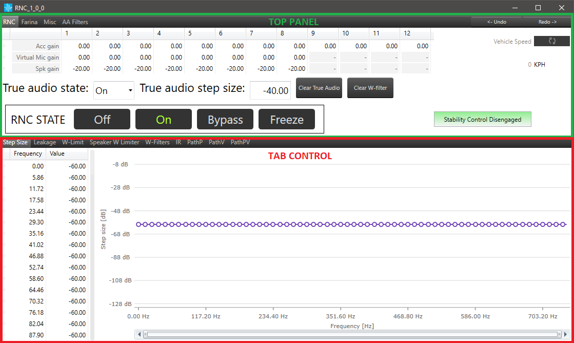
4.1.Top panel
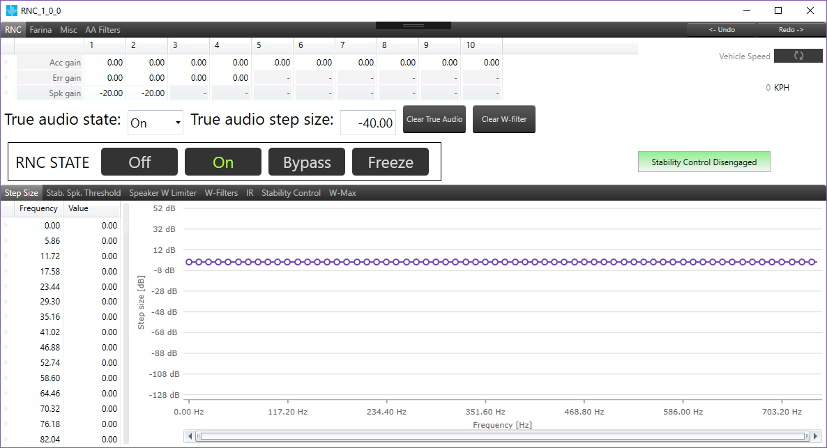
4.1.1.Top panel table
Depends on the SFD configuration table will contain different rows. By default, when Virtual Microphones are disabled, the table has three rows:
- Acc gain
- Error gain
- Spk gain
When the user enables Virtual Microphones, Error gain row will be switched to Virtual Mic gain.
The number of elements for each column is defined by parameter configuration in SFD.
Like all of the tables in GTT, the user can use keyboard shortcuts for copy/paste.
4.1.2.Top panel parameters
Below the gains table, there is a section which contains parameters for True audio, in which the user can set step size and state for True audio.
On the right side a section for often used information, settings and actions can be found:
- Clear W-filter (more in section W-Filters)
- RNC state – one of four states can be selected (Off/On/Bypass/Freeze)
 Selected state is marked as green.
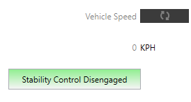
 - Stability Control – inform about stability control state and is visible when stability control is supported by RNC. It can be:
- grey when FDDL Mode is in disabled state
- green when FDDL Mode is in retry or dyn. leakage state and instability detected is 0
- red when FDDL Mode is in retry or dyn. leakage state and instability detected is greater then 0,
The caption of label can be
-
- “Stability Control Disabled” when label is gray
- “Stability Control Engaged” when label is green
- “Stability Control Disengaged” when label is red
- when FDDL Mode is in retry mode then label contain number of retries in brackets ex:”Stability Control Engaged (6)”
- Activate polling – automatically refresh the Vehicle speed and Stability control. By default polling is off, after clicking it, arrows on the button will change to green color and the polling will start
4.2.Tab control
Following tabs are available for RNC mode:
- Step size
- Leakage
- Flexible Adaptation Leakage
- W-Limit
- W-Filters
- IR
- PathP
- PathV
- PathPV
- Stability Control
- Stability Speaker Threshold
- W-Max
- ACC Stability Control
- Stability ACC Threshold
- ACC Max
- Limiter Leakage Monitoring
- ACC Gain
4.2.1.Step size
The panel displays values for the step size. The user has the possibility to modify the values for each frequency using both panel elements (table and graph). The value is automatically sent to the device after the change. The maximum and minimum value is taken from xAF dll which contains a definition for RNC object.
4.2.1.1.Using grid and graph
Using Grid
Values in the grid can be modified in a few different ways:
- Input value to specific cell
- Copy/paste value from excel file
- Change value by keyboard
- Up/Down key – will increase/decrease value depends on current location (integer or fractional part)
- PgUp/PgDown key – below table represents value changed based on range and key configuration
| Key combination | Jump |
Range: 0 – 1 |
Range: 1 – 10 |
Range: 10 – 100 |
Range: 100 – 1000 |
Range: 1000 – |
| Shift | Small | 0.001 | 0.01 | 0.1 | 0.1 | 1 |
| <nothing> | Middle | 0.01 | 0.1 | 1 | 1 | 10 |
| Ctrl | Large | 0.1 | 1 | 10 | 10 | 100 |
Using chart
Values can be changed by dragging the chart point.
The chart can be zoomed by:
- mouse scroll
- selecting chart area
- page up/page down keys
When chart is zoomed user can move chart with Shift key pressed.
When functional keys are pressed (e.g. Ctrl, Alt, Shift) it is not possible to zoom a chart by selecting the chart area.
Synchronization
Changing values on the chart will update the corresponding value in the table and vice versa.
4.2.2.Leakage
The panel structure and possible operation are the same as on the Step Size panel.
The panel is not available when SFD configuration parameter “W FilterLeakage is enabled” is set to 0.
How to use grid and chart described in Using grid and graph

4.2.3.Flexible Adaptation Leakage
Flexible Adaptation Equation is an improved filter update equation in the RNC update path. Compared to the previous filter update equation, the improvements include individualized step sizes for each accelerometer, better accelerometer power averaging equation and a new leakage feature called Flexible Adaptation Leakage (FAL).
Flexible Adaptation Leakage is an optional feature under FAE (Flexible Adaptation Equation) . It is a new leakage calculation method when enabled and will scale leakage according to the normalized step sizes.
Number of graphs for each row corresponds with the design time parameter called “Number of Accelerometers”, normally configured to be 12.

Flexible Adaptation Leakage Tab
Leakage Gamma 3 values

Flexible adaptation leakage tab shows 128 Gamma 3 values.
Enable Flexible Adaptation Leakage
![]()
Flexible adaptation leakage tab provided option to disable/ enable flexible adaptation leakage.
Refresh option
![]()
Flexible adaptation leakage tab provided option to refresh graphs.
Refresh option will read normalized step acc X data for the first row and all two rows of graphs will be refreshed and updated.
Normalized step size acc X Graph

GTT will show normalized step size acc X graph mapped with normalized step size values.
Leakage acc X Graph
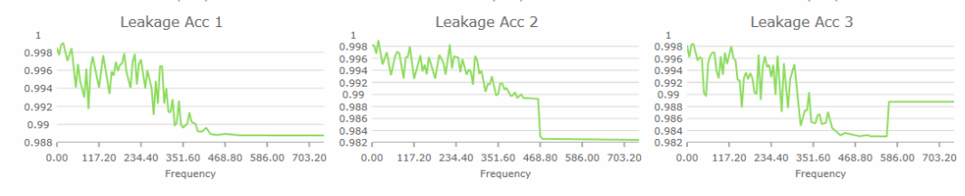
Leakage Acc X are calculated by GTT when refresh is clicked.
The formula is Leakage Acc X = 1 – (vector dot product between Gamma3 and Normalized Step Size Acc X).
4.2.4.W-Limit
The panel structure and possible operation are the same as on the Step Size panel.
How to use grid and chart described in Using grid and graph

4.2.5.Speaker W Limiter
The tab “Speaker W Limiter” has one grid represents two parameters “W Threshold” and “Global leakage” for each speaker. During vehicle tuning, either because of too aggressive step size tuning or low coherence between sensor and microphone, there can be boosting noise in certain situations. Every speaker has different contribution to the performance and boosting. Speaker W Limiter is designed to limit W filter applied to each speaker. It can restrain W coefficients from overgrowth, and speaker dependent design gives freedom to control the contribution of different speaker.

4.2.6.W-Filters
Based on the configured number of accelerometers and speakers, the panel is displaying a chart for each combination.
On the left side there are buttons which allow a user to perform the following actions:
- Load W-Filters – load coefficients from CSV file
- Save W-Filters – save coefficients into CSV file
- Clear W-Filters – set all values to default, please notice that values are cleared separately by UI and Audio Object. This action can also be performed by a button inside the top panel.
- Read W-Filters – read coefficients from device
- Send W-Filters – send coefficients to device
- Turn On/Off polling – when it is on, the panel will continue requesting coefficient values from the device

4.2.7.IR
Based on the configured number of microphones and speakers, the panel will display two charts (for Amplitude and Phase) for each combination.
IR measurement can be started only when the object is in Farina mode. More about IR measurement in IR Measurement
It is possible to compare the current measurement with a previously saved one.
On the top of the IR view there are buttons which allow the user to perform the following actions:
- Export – export data into a CSV file, the file contains real part and imaginary part, this can be performed also from PathP, PathV, PathPV tab
- Import – Import data from CSV file and automatically sends it to the device, this can be performed also from PathP, PathV, PathPV tab
- If the comparison is active it will be cleared
- If import file contains data for PathPV and Virtual Microphones are disabled then data for them will be ignored
- Compare – import second series from CSV file and display it on the chart for comparison purpose, this will not send any data to the device
- Clear compare – remove the second series from the chart

If RNC has enabled Virtual Microphones then PathPV data will be exported. When Virtual Microphones are disbaled then all VM path data will be filled with zeros.
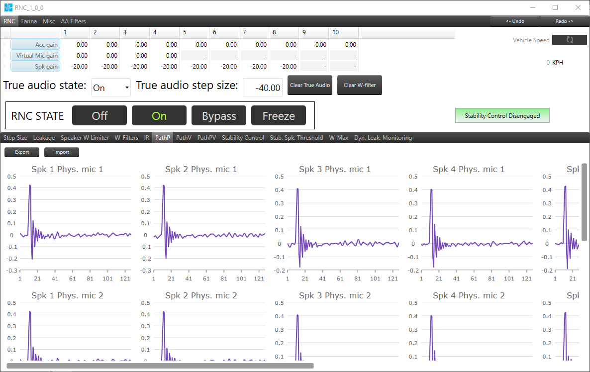
4.2.8.PathP
Based on the configured number of speakers and microphones, the panel will display a chart for each combination.
The panel is only available when SFD configuration parameter “Virtual Mic support enabled” is set to 1.
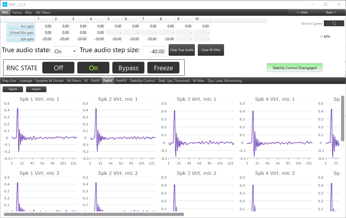
4.2.9.PathV
Based on the configured number of speakers and virtual microphones, the panel will display a chart for each combination.
The panel is only available when SFD configuration parameter ‘Virtual Mic support enabled’ is set to 1.
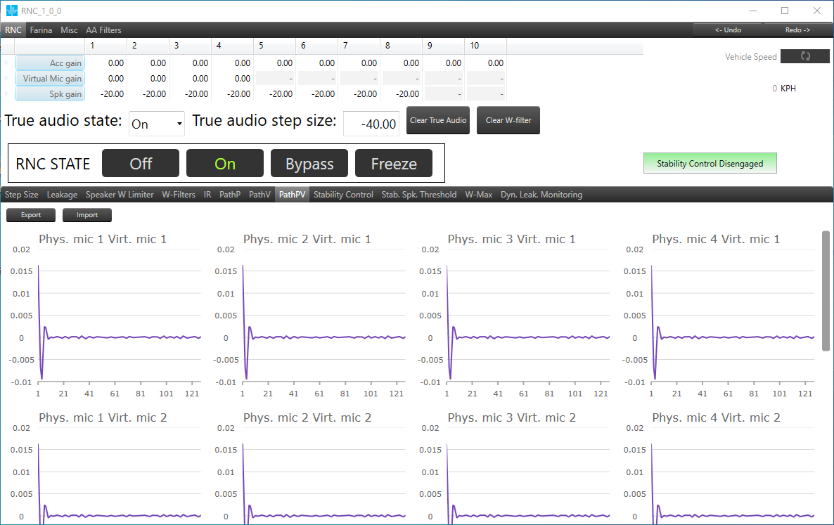
4.2.10.PathPV
Based on the configured number of physical microphones and virtual microphones, the panel will display a chart for each combination.
Data which are displayed are filled after PV Measurement is performed, which can be done in Farina mode (Path-PV Measurement)
The panel is only available when SFD configuration parameter ‘Virtual Mic support enabled’ is set to 1.
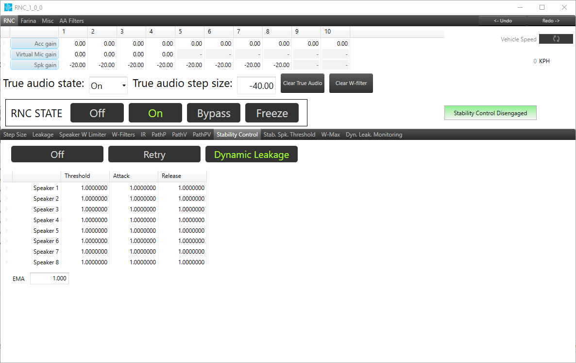
4.2.11.Stability Control
Stability Control tab can be found in RNC mode.
It is used to control detected RNC instability, which can happen if W-Filter coefficients became abnormal.

It contains three buttons (Off, Retry, Dynamic leakage) which are responsible for changing stability method.
When instability will be detected, user can choose two actions:
- Off – which causes RNC deactivation based on retry times
- Dynamic Leakage – which casues RNC performance degradation and RNC deactivation based on leakage (used to control boosting)
In Retry mode, there are two textboxes responisble for tuning “Retry Count” and “Wait time(s)” parameters.
Retry count determines number of attempts for RNC deactivation.
Wait time determines time, which runs out between retry attempts.
In Dynamic leakage mode there is table for tuning “Threshold“, “Attack” and “Release” parameters for each speaker.
EMA textbox is responisible for tuning Deactive Average Weight parameter.
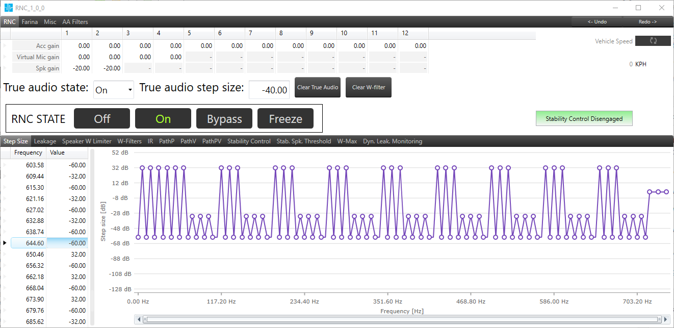
4.2.12.Stability Speaker Threshold
The panel displays values for stability speaker threshold. The user can modify the values for each frequency using both panel elements (table and graph). The value is automatically sent to the device after the change. The number of columns is depended on the number of outputs (# of Audio Out) configured on SFD. The maximum and minimum value is taken from xAF dll which contains a definition for RNC object.
How to use grid and chart described in Using grid and graph

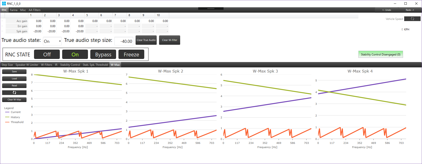
4.2.13.W-Max
The W-Max tab is used to display the maximum values of W coefficient amplitude per frequency bin and per speaker. Displays three series for each speaker. The Current and History comes from device and can be read on demand by Read button click. The periodic reading, every 1 sec is also possible by the toggle button. The Threshold series comes from Stab. Spk. Threshold tab and it can be modified there.
On the left side there are buttons which allow a user to perform the following actions:
- Save – save all three series for all speakers to .csv file.
- Load – load threshold series for all speakers from file saved by Save button.
- Read – read Current and History data for all speakers from device.
 – automatically refresh the Current and History data. By default polling is off, after clicking it, arrows on the button will change to green color and the polling will start.
- Clear W-Max – sets 0 for all history values on charts and device.
4.2.14.Dynamic Leakage Monitoring
This tab is available when Stability Control is in Dynamic Leakage mode. User can observe four parameters per each speaker.
- Dyn. leak. is a FDDL leakage currently applied by stability control algorithm.
- Min. dyn. leak. is a minimal value of FDDL leakage applied by stability control algorithm since turning on RNC. This statistic can be cleared with Clear W-Max button.
- EMA dyn. leak. is a current value of leakage computed by Exponential Moving Average algorithm. It is being compared with threshold value. If EMA dyn. leak. for any speaker is below threshold RNC is muted to the next key-cycle (or clearing W-filters).
- Min. EMA dyn. leak. is a current value of leakage computed by Exponential Moving Average algorithm since turning on RNC. This statistic can be cleared with Clear W-Max button.
When pooling button is active (green) then data are refreshed every one second.
![]()
– pooling button

4.2.15.ACC Stability Control
The ACC Stability Control tab is accessible in RNC mode when the tuning version of the RNC object is equal to or greater than 3.

ON and OFF Buttons on ACC Stability Control tab is provided to enable and disable FDDL-X mode.
If FDDL-X mode is enabled (ON), the following parameters are available in this tab, which can be modified.
| Parameter | Range | Default Value |
| Xslew | 0 to 1 | 0.99 |
| Attack | 0 to 1 | 0.8 |
| Release | 0 to 1 | 0.1 |
When FDDL-X mode is enabled, the following tabs will be displayed next to ACC Stability Control tab.
- Stability ACC Threshold
- ACC Max
- Limiter Leakage Monitoring
4.2.16.Stability ACC Threshold
This tab is to show ACC Threshold values of all accelerators. These threshold values vary with the frequency range.
The frequency range 0-750 Hz divided into 128 intervals and threshold values for all these intervals are shown in a table.
Default threshold value is 16384 and it can be edited.

Once ACC current value is greater than ACC Threshold value, FDDL-X will be triggered for particular accelerator and frequency. Corresponding cell in the table is highlighted with red border.
4.2.17.ACC Max
This tab is to show the Max, Current and Threshold values of ACC per bin. Values for each accelerator are displayed in separate charts.
Charts displays three series for each accelerator.
- ACC Current
- ACC Max
- ACC Threshold
The Current and Max values come from device and can be read on demand by Read button click. The periodic reading, every 1 sec is also possible by the toggle button.
The Threshold series comes from Stability ACC Threshold tab and it can be modified there.

On the left side of the interface there are buttons that allows you to perform following actions:
- Save: You can save ACC Max for all accelerators to .csv file in below format.

- Load: You have the option to load the ACC Max values for all accelerators from a file that was saved using the “Save” button.
- Read: You can read Current and Max data for all accelerators from device.
- Refresh
 : Automatically refresh the Current and Max data. By default, polling is off. After clicking it, arrows on the button will change to green color and the polling will start.
 - Clear ACC Max: Sets zero for all ACC Max values on charts and device.
4.2.18.Limiter Leakage Monitoring
This tab is to monitor Limiter Leakage Value.
Refresh option is available to automatically refresh current Limiter Leakage value in every 1 sec.
The data of last 12 sec are shown in a chart and current Limiter Leakage value is available in left side of the chart.

4.2.19.Diagnostics
On this tab, the monitor Instability Counter and Speaker Unstable values are displayed.

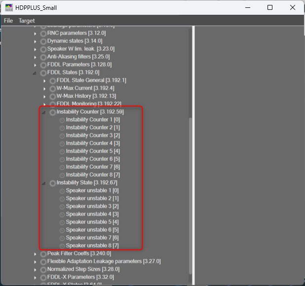
The count of Instability Counters and Speaker Unstable state variables are based on number of audio output channels of RNC audio object.
4.3.Shaping
This tab is for controlling peak noise cancellation.
It is the main tab visible only when RNC mode is selected. This tab is visible from Q-release version and above.
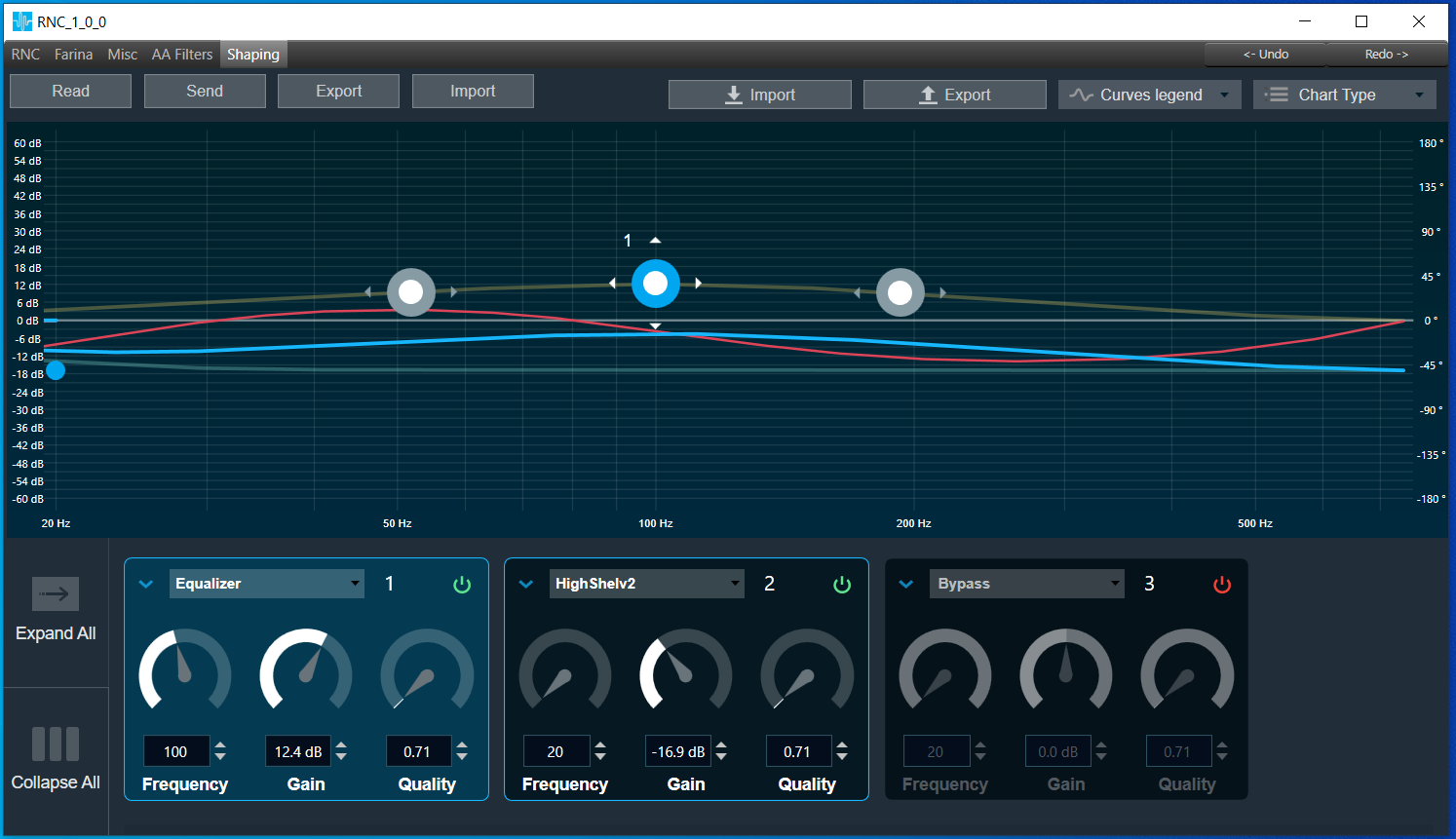
It consists of customized biquad panel:
- Sample rate 15000
- Biquad count 8
- gain in range: -60dB ~ +60dB
- quality in range: 0.1 ~ 116
- frequency in range: 20Hz ~ 735Hz
- 128 coefficients calculated for real and imaginary frequency response
- allows to use filter types provided in DDF and supported by biquad panel
Read
Allows reading all shaping parameters and coefficients from the device. Displays coefficient mismatch toast message when coefficients received from the device doesn’t match coefficients calculated by the panel.
Send
Allows sending all shaping parameters and coefficients to the device. The shaping panel by default doesn’t support online value synchronization.
Export
Allows exporting of all shaping parameters and coefficients with RNC audio object configuration information to the specific file. The format is as follows:
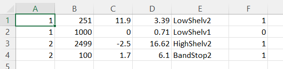

Import
Allows importing shaping parameters and coefficients from the file. Displays coefficient mismatch toast message when coefficients imported from file doesn’t match coefficients calculated by the panel.
5.Farina mode
Like RNC mode Farina panel is split into two parts:
- Measurement part
- Tab control
5.1.Measurements
5.2.IR Measurement
IR Measurement can be launched only in Farina mode. While measurement is in progress UI is blocked.
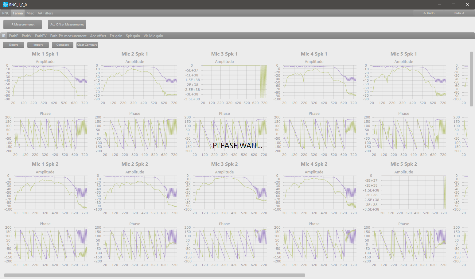
Timeout for measurement is set to 1 minute. If the measurement is not finished after the timeout, UI will be unblocked, and the chart will not be updated.
All panels below are visible in both modes: RNC and Farina and will be updated after successful measurement:
- IR
- PathP
- PathV
5.3.Accelerometer Offset Measurement
Accelerometer Offset measurement is only available when SFD configuration parameter ‘Accels Offset Calib. Enabled’ is set to 1. Similar to IR measurement, for this action UI is also blocked and the timeout is set to 1 minute.

When calibration is turned off, then hovering your mouse over the calibration button will result in a tooltip with ‘Accelerometer Offset Calibration disabled’ message to appear.
5.4.Tab Control
5.4.1.ACC Gain
The ACC Gain tab is available in Farina mode when the tuning version of the RNC object is equal to or greater than 3. The ACC Gain tab is used to obtain statistical values of the accelerometer.
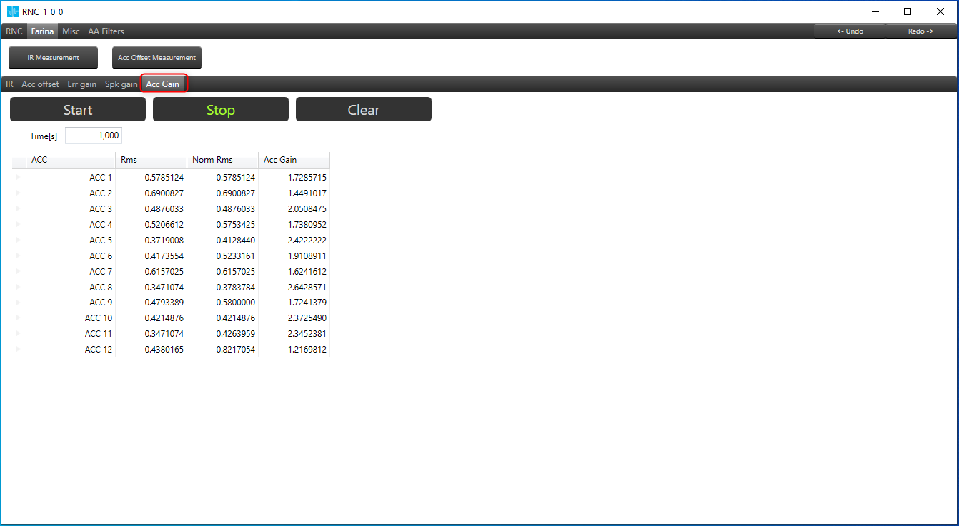
Following are the options available in this tab:
- Start – This button is to start calculation process in the device.
- Stop – This button is to stop calculation process in the device.
- Clear – This button is to clear the values in table and device.
- Time[s] – The calculation time can be configured and sent to device from this tab.
The Rms values of each accelerator are shown in this tab. The table displays the calculated Normalized Rms and ACC Gain values for each accelerator, which are derived from the provided values.
6.Misc tab
Miscellaneous tab does not update the selected RNC mode on the device. This tab is used to store global configuration values for both modes.
It is possible to set following parameters:
- Speaker Limiters threshold
- Accelerometers Limiters threshold
- Global Speaker ramp time
- eNormalization FxErr Smoothing factor
- eNormalization MIC Power Coeff
- eNormalization FxErrMaxPwr Contribution
Input fields have a validation mechanism. Minimum and maximum values are taken from the RNC audio object.

7.AA Filters
AA Filters is placed in separate tab in RNC. AA Filters tab contains two other sub tabs “Filters sets” and “Filter sets control”.
7.1.Filters sets
This tab allows user to set filter coefficients for three sets, observe filters sets characteristic on appropriate graphs on the right and check if coefficients on the filter set are stable. Support only three sets (Set #1, Set #2, Set #3)
Table allows user to change coefficients value on each available set
Each filter coefficient value change, triggers following actions:
- updating given state variable value
- refreshing graph
- updating status on a given set
The graph is used for visualization for filter coefficient sets. Displays amplitude and phase.
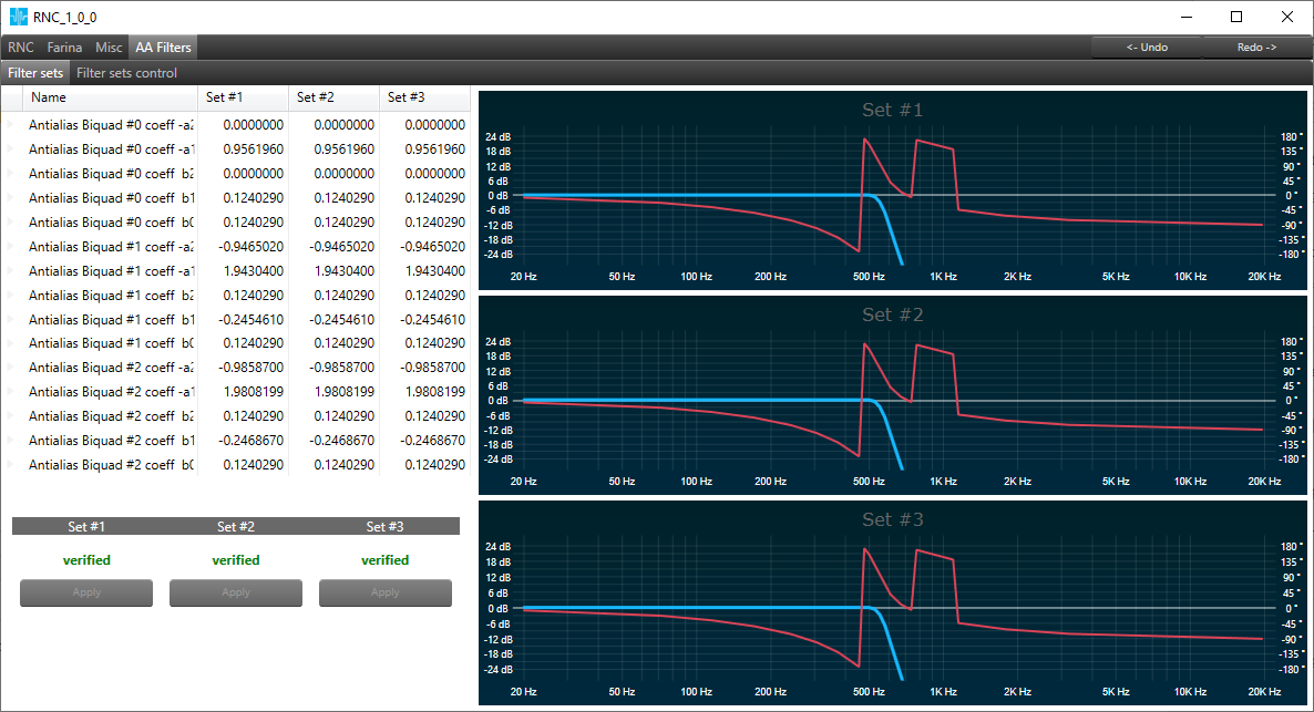
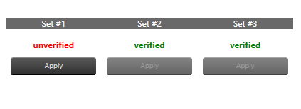
Verification panel allows user to verify if coefficients in given set are stable.
1 – Updated – verified
0 – Changed – unverified
The Apply button is enabled only for unverified set.
Applying filter set checks if coefficients in given filter set are stable.
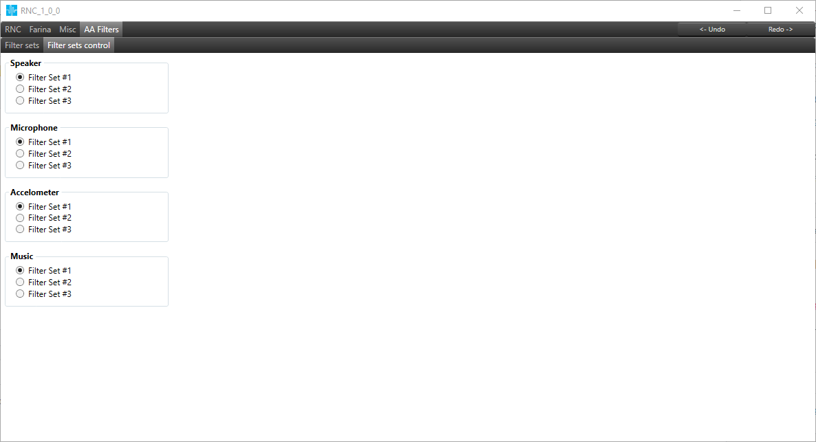
7.2.Filters sets control
Filter sets control view allows to change configuration of active set on the Speaker, Microphone, Accelometer and Music.
8.Undo/redo functionality
In the right top corner of panel there are two buttons – Undo and Redo. Up to 20 actions can be undone. The table below represents which actions are included in the Undo/Redo mechanism.
| Action | Available | Not available |
| Changing value in textbox | X | |
| Changing value in Combobox | X | |
| Changing value in the table (single and bulk) | X | |
| Turn on / turn off polling | X | |
| Clear W-Filters | X | |
| Switching mode | X | |
| Switching tab | X | |
| Changing value on the chart | X | |
| File operation (load, save, import, export) | X | |
| Changing value by slider | X | |
| Update after measurement | X |