Using analyzer, you can measure and analyze various aspects of an audio signal. It can be used to measure characteristics such as frequency response, amplitude, distortion, and noise level.
| Settings | Descriptions |
| Banding |
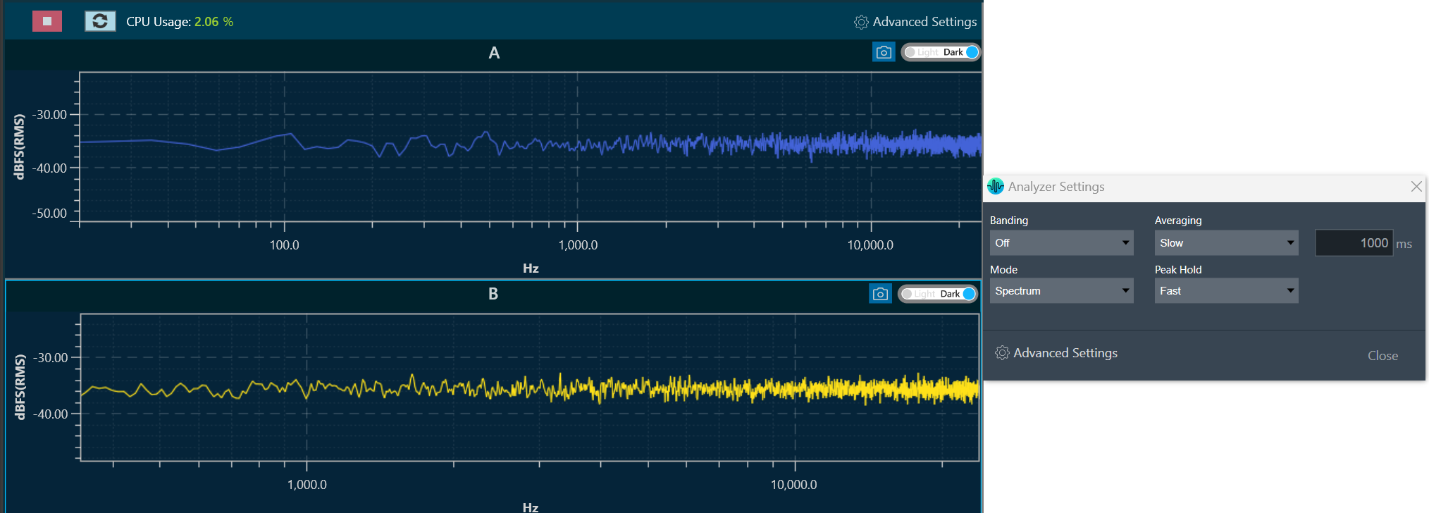
In Spectrum or Multiplexer mode, it is possible to adjust the “Banding”. When the banding is turned off, all frequency bins of the spectrum are displayed, allowing for a highly detailed analysis. However, this setting requires more CPU power as the amount of data that needs to be calculated and displayed increases with the FFT size. Spectrum mode is shown in the example below when Banding is turned off. On the other hand, when banding is turned “On”, frequency bins are grouped together. The width of each group can be adjusted by fractions of an octave, such as Oct12, which means that one band has the width of a 12th of one octave. Spectrum mode is shown in the example below when Banding is turned on. |
| Mode | Using Mode option, you can select different analyzer mode from the drop-down list. The available modes are listed below.
|
| Averaging |
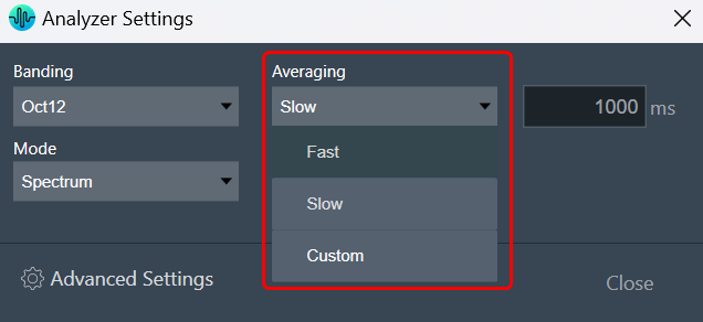
Depending on the test signal, smoothing of the spectrum over time is required. This can be set by the “Averaging” option.
Following are the averaging options available.
|
| Peak Hold |
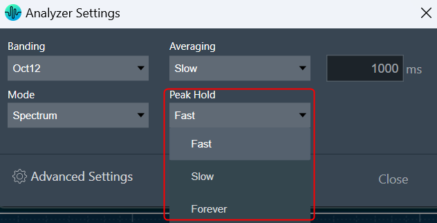
You should be able to select time constant for peak trace. Depending on the time constant setting, the peak hold trace shall show the maximum value which occurred within the defined moving time window.
Peak Hold settings include:
|

Advanced RTA Setting
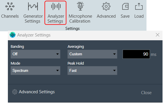
Click on the “Analyzer Settings” to open the advanced RTA setting dialogue box. Here you can configure different analyzer settings.
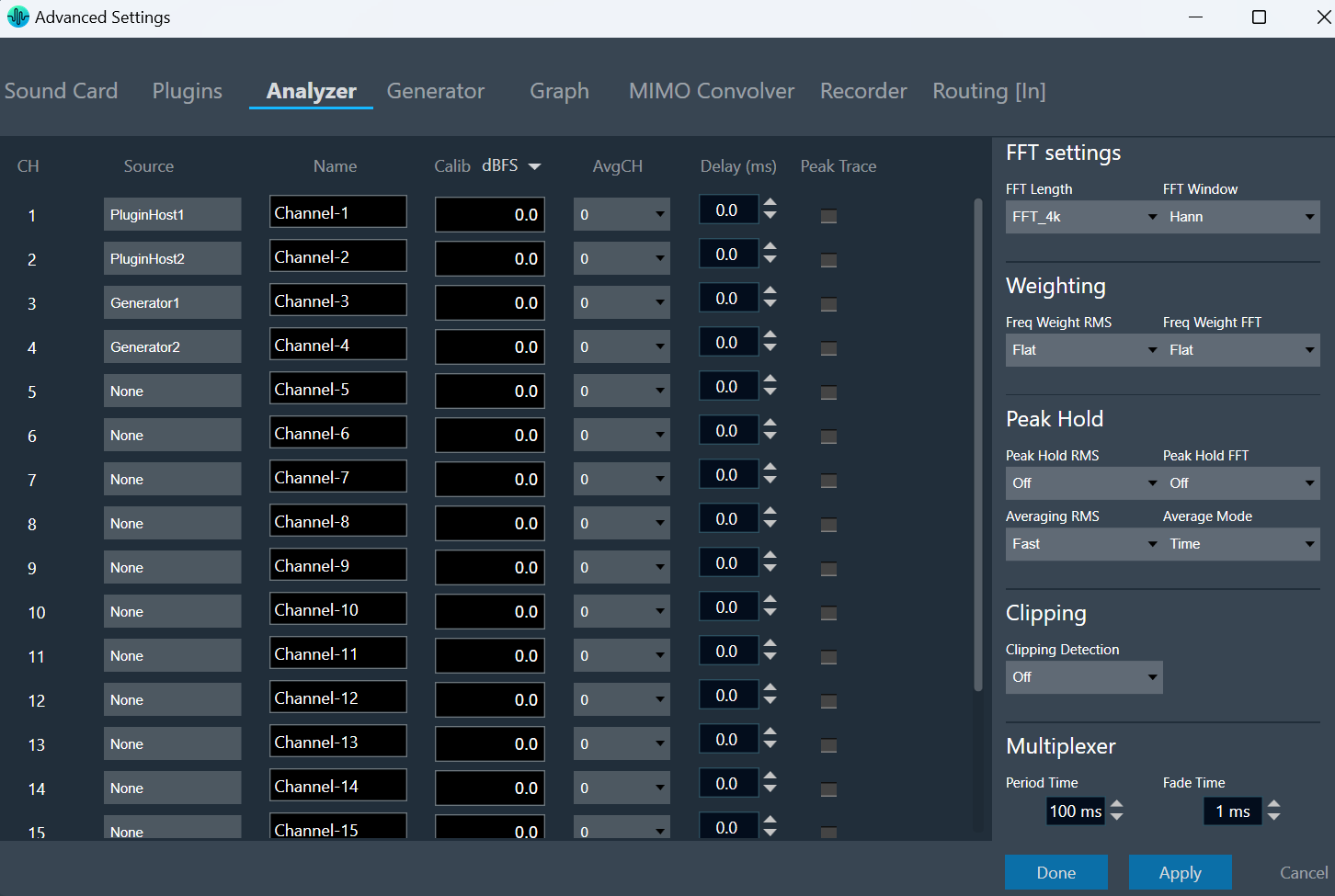
The following modifications can be made in the Analyzer setting window using the channels list:
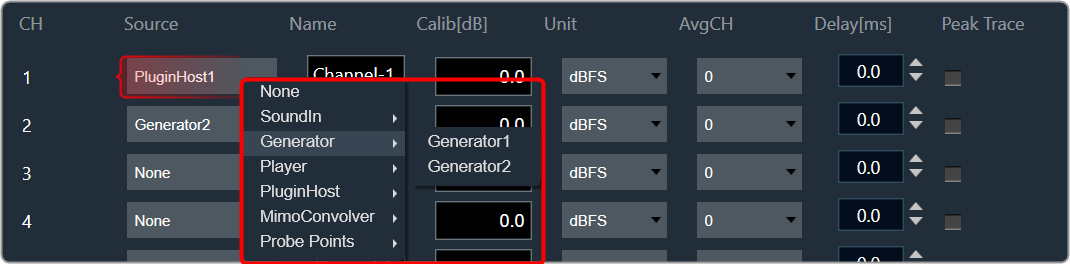
- Source: This defines the input of a certain analyzer channel. By clicking on the control a context menu pops up from which the desired source can be chosen.
If there is no input available, None will be shown as the source by default.
- Name: Enter the name of an analyzer channel. This name appears in the channel viewer and will be set as a default name when storing measurements as traces.
- Calib[db]: When a channel is being calibrated for a certain microphone the determined value appears here. It can also be overwritten by entering a desired value. The unit is “dB”; the analyzer input stream will be scaled by this value.
- Unit: Allows you to set the analyzer source unit. This unit appears later in the channel viewer.
- AvgCH: When the analyzer is in “Multiplexer” mode this control determines to which “Average” channel the analyzer source is added.
When the channel is “0,” it is not included; when it is “1” or “2,” it is added to “Average-1” or “Average-2,” respectively. - Channels 17 and 18 are reserved for the “Average” channels. Here only the name can be edited.
- Delay: Add or subtract time delay in milliseconds. In Phase measurement we can add/subtract time delay to compensate HW and/or acoustic delay.
- Peak Trace: Peak hold trace allows analyzer to display a secondary live trace for each channel showing the highest amplitude values for each frequency. This feature helps to mark the highest amplitude reached at each frequency.
By default all the peak trace will be disabled. This can be enabled using the checkbox available in the analyzer settings tab for each channel.
Click “Delete” in the data context menu of the peak trace in the trace list to reset the peak trace. When a peak trace is deleted, the database will also delete the current peak trace and create a new one.
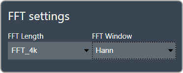
| FFT Settings |
The length of the FFT which is used for the spectrum calculation can be set between starting from 4096 up to 131072 samples (4k to 128k). The higher the value, the finer the frequency resolution of the spectrum. But with increasing lengths the CPU load will increase due to the higher number of calculations and data to plot.
You can specify how a finite data set is extracted from the roughly infinite input data stream using the “FFT Window”. The “FFT Length” determines how the data set is cut out. For more details about windowing, refer to the Window Functions. “Hann” will be the default value for the FFT window. |
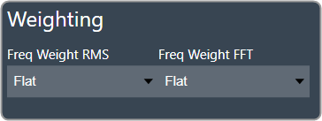
| Weighting |
The Weighting function allows you to select how the input signal is weighted across the frequency range. This can be customized separately for time domain measurements (Freq Weight RMS) and frequency domain measurements (Freq Weight FFT).
For more details about weighting, refer to the A-weighting. |
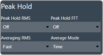
| Peak Hold | The Peak Hold function enables you to independently adjust measurements in the time domain (Peak Hold RMS) and frequency domain (Peak Hold FFT).
Averaging RMS: The time constant for the RMS calculation can be selected under “Sound Level Meter”.
Average Mode: The analyzer mode “Multiplexer”, where multiple channels are added to a single “Average” channel can be set to “Time” and “Freq”.
|
| Clipping |
Clipping occurs when the input signal exceeds the full-scale range of the input sound device. RTA can detect this condition and signal it. There is also an option to exclude the data packet which contains clipped data from the analysis.
Clipping Detection mode includes:
When data are clipped, and the detection is enabled a “DATA CLIPPED” message on the top right corner of the graph is shown. |
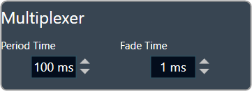
| Multiplexer |
Activating the multiplexer mode to “Time” allows you to set the length of a time slice (referred as “Period Time”) and the time duration for fading one channel into the next (referred as “Fade Time”).
|