1.Terms and Abbreviations
| Abbreviations | Meaning |
|---|---|
| GTT | Global Tuning Tool |
| xAF | Extendable Audio Framework |
| VST | Virtual Studio Technology |
| SFD | Signal Flow Designer |
2.Overview of Control Modulator
Control Modulator is audio object that modulate control input signal with many choices for functions and LUTs. There are two control modulator play modes, loop and one-shot mode. The total time of control modulator depends on duration time. There are two components in control modulator, modulator section, modulator action. Output are from modulator action. Modulator section is responsible for modulation function, sin, square, sawtooth, triangle, random or LUTs. The LUT definition is provided as a two-dimensional array, called a “xy-map” with n points. It is assumed that for all points, the x values are rising from zero. For each x value there is a corresponding y-value representing the output. X values are from zero in millisecond unit. Modulator action modulate input with output of modulator section. In principle, Control Modulator is a set of modulations to make input control signal more realistic. The above property of Control Modulator makes it a useful component of Electronic Sound Synthesis, especially when the main purpose of ESS is to generate sound for electric vehicle.

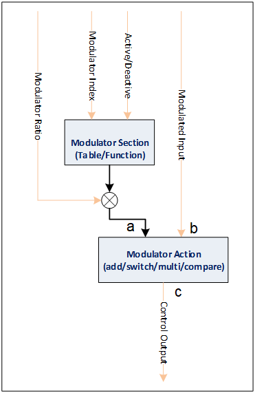
Modulator Index: The index of modulator in modulator section
Active/Deactive: Active/Deactive modulator section
Modulated Input: The control input which will be modulated
Modulator Ratio: The ratio to modulator
Control Output: The output of Control Modulator object
3.Build time parameters

| Configuration parameter | Values |
| Object Mode | “Loop” or “One Shot” |
| Function Number | 0 – 64 |
| Table Number | 0 – 64 |
| Table Height (1-64) | 2 – 256 |
4.Table View
The table view of Control Modulator contains LUT panel’s table and chart.
The number of tabs for Table View depends on “Table Number” value in SFD configuration.
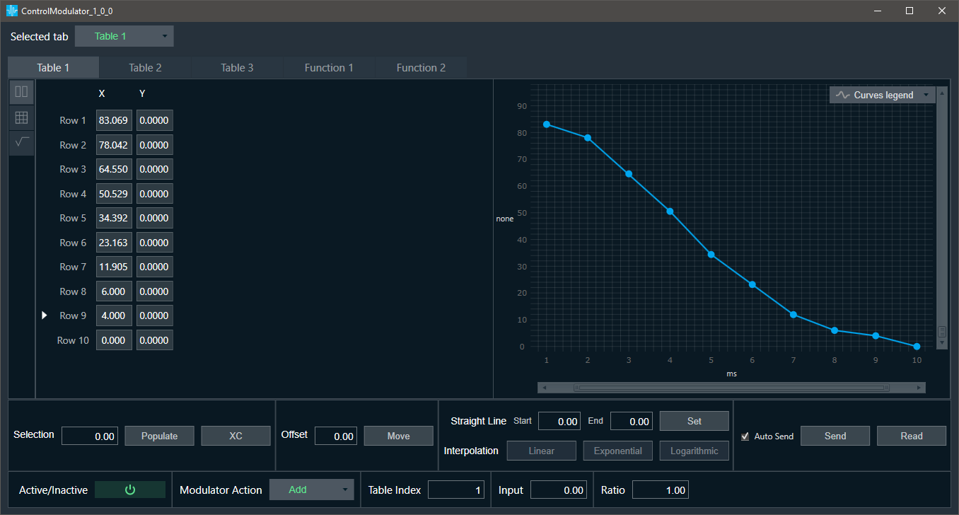
Userguide for LUT panel can be found here: LUT Userguide
5.Function View
The number of tabs for Function View depends on “Function Number” value in SFD configuration.

Control Modulator enables to choose several function calculation types from combobox:
- Sine
- Square
- Triangle
- Sawtooth
- Random
The chart displays graph for selected function type, based on tuning parameters:
- Frequency
- Max data
- Min data
- Phase data
- Duration Time
The default scale of chart is from 0 to 1200 (X axis)
Min and Max data define ranges for Y axis.

If Function is set to “Random”, there is no chart, but there are several tunable parameters:
- Standard Deviation
- Max Deviation
- Min Deviation
- Smoothing Factor
- Random Type
Function modulator native panel Random Function add Random Type:
- Integer = 0.0
- Float = 0.0
When Random Type = Integer, the Input of Standard Deviation and Smoothing factor should be invalid.
6.Common View

The Common View of Control Modulator is visible on both table view and function view tabs.
It enables to set of two types of parameters Tuning Parameters and State Parameters:
- Tuning Parameters
- Active/Deactive: Active/Deactive modulator section
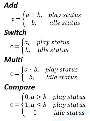
- Modulator Action, to determine calculation result for output:
- Add
- Switch
- Multi
- Compare
- Update ratio
- Blocks
- State Parameters
- Status
- Table Index: The index of the modulator in the modulator section
- Input: The control input which will be modulated
- Ratio: The ratio to the modulator
- Frequency
Modulator Action results: