1.Interface Objects
Interface objects category contains following audio objects.
1.1.AudioIO
The AudioIO audio object acts as the interface object between the xAF instance and other audio objects in the single flow design.
This AudioIO object can be configured to either receive audio data (AudioIn) from framework or pass the processed audio (AudioOut) back to the framework.
- When configured as AudioIn, this object copies the audio data from the input audio buffers of the framework to the output buffers of this audio object that is accessible to other audio objects in the pipeline.
- When configured as AudioOut, this object copies the audio data from its input buffer to the output buffers of the xAF instance.
Use Cases: This object can be deployed whenever an audio buffer needs to be sent or received by the framework.

AudioIO Properties
Below table provide the details about AudioIO audio object properties and functionality.

| Properties | Description |
|
# of Audio Out Or # of Audio In |
Enter the number of audio input or audio output. For any xAF instance, the SFD can have only one input AudioIO object and one output AudioIO object. The number of audio channels of this object shall be same as the number of audio IO of the instance.
|
| Display Name | Display name of the AudioIO audio object in signal flow design. It can be changed based on the intended usage of the object. |
| Object Mode | The AudioIO audio object supports following two modes.
|
Mode
The AudioIO audio object supports following two modes:
- Audio In: In this case the AudioIO audio object is used to receive audio data from the xAF instance (source). The object will have only audio outputs in this mode to pass the audio to subsequent objects for processing.
- Audio Out: In this case the AudioIO audio object is used to send audio data back to the xAF instance (sink). The object will have only audio inputs in this mode to collect the processed audio and pass it back to the xAF instance audio buffers.
Additional Parameters
There are no additional parameters available for AudioIO audio object.
Tuning Parameters
There are no tuning parameters available for AudioIO audio object.
Control Parameters
There are no control parameters available for AudioIO audio object.
Native Panel
AudioIO audio object does not support native panel.
1.2.ControlIn
The ControlIn audio object is deployed to connect the external control signals to the audio objects used in the signal flow. Each framework instance can have only one instance of this ControlIn object. This object serves as the consolidation point for all the control inputs for the framework instance.
Use Cases:
- Use case 1 –Central volume control received (0 to 100% volume) from the Head unit will be forwarded to the controlIn AO. User can design the signal flow using LUT to convert the percentage volume to db unit and send it to Volume AO to manipulate the audio signals.
- Use case 2 – Bass and treble input from user can be converted to Frequency, Gain and Quality factor for Tone control audio object to give desired affect for the audio signal.

ControlIn Properties
Below table provide the details about ControlIn object properties and functionality.

| Properties | Description |
| Number of Control Output | The number of control output signals is configurable.
|
| Display Name | Display the name of the ControlIn object in signal flow design. It can be changed based on the intended usage of the object. |
Additionally, in the ControlIn object you can configure the Control ID for each control pin.
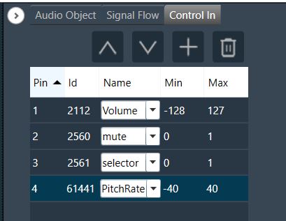
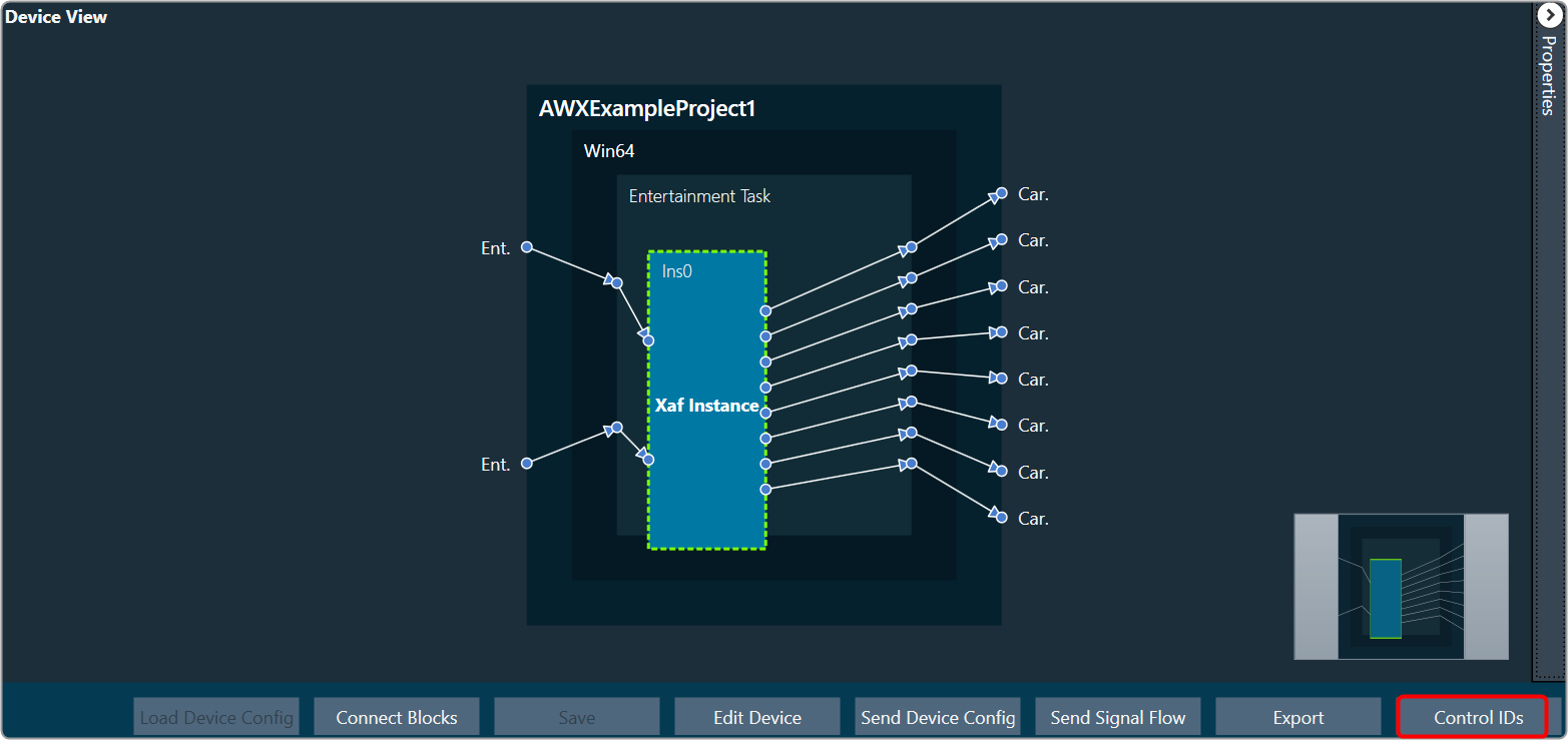
The Control IDs can be selected from the available list or you can add the new custom Control IDs. For more details on adding and editing control ID, refer to Control IDs.
Mode
There are no modes available for ControlIn object.
Additional Parameters
There are no additional parameters available for ControlIn object.
Tuning Parameters
There are no tuning parameters available for ControlIn object.
Control Parameters
The ControlIn object pass through the control signals received from the framework instance on the configured pins. Additionally there are no control parameters available specifically to control the functioning of this object.
Native Panel
ControlIn object does not support native panel.
1.3.ControlOut
The ControlOut audio object is a framework level object, that ties directly with the framework’s control system. The purpose is to take control values from an xAF instance (AudioProcessingBase) and make them available externally.
The ControlOut audio object accepts any combination of controls – single or block.
Use Case: This object can be deployed whenever framework wants to access any control value of a signal flow. Platform may want to access these values from the framework.
ControlOut Properties
Below table provide the details about ControlOut object properties and functionality.
| Properties | Description |
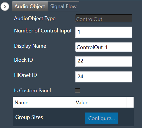
| Number of Control Input | The number of control Input signals is configurable.
|
| Display Name | Display the name of the ControlOut object in signal flow design. It can be changed based on the intended usage of the object. |
Mode
There are no modes available for ControlOut object.
Additional Parameters
| Parameters | Description | |
| Group Sizes |
This is an additional parameter which is an array with a length equal to NumElements Each value in this array is the size of the corresponding control. Example: [1,2] would mean the first control input is a single control, but the second is a block control of size 2. |
 |
Tuning Parameters
There are no tuning parameters available for ControlOut object.
Control Parameters
There are no control parameters available to control the functioning of this object.
Native Panel
ControlOut audio object does not support native panel.
2.Basic Objects
Basic objects category contains following audio objects.
2.1.Delay
The purpose of the Delay audio object is to time shift between the input and output audio samples. The audio object has the ability to add delays to several channels, each with a different delay setting.

However, each channel will support the maximum allowed delay set in SFD. As a result, each channel will have a buffer that is the appropriate size to handle the maximum delay. The Delay audio object can be used when a time delay is required in an audio pipeline. The objects supports DelayPool functionality as an operating mode. In this mode, sum of the individual channel delay configured will be less than or equal to the maximum delay.
Use Case: The Delay audio object can be used when a time delay is required in an audio pipeline.
Delay Object Properties
Below table describes about the Delay audio object properties and functionality.

| Properties | Description |
| # of Channels | The number of channels is configurable in the SFD and is always equal to both, the number of input and output channels.
|
| Max.delay(ms) | Specifies the maximum possible delay for each channel in audio object. For Delay Pool (Refer below on mode details) mode Max Delay is maximum delay which can be utilized by all channels combined.
Max delay value specified in milliseconds (ms). |
| Display Name | Display name of the Delay audio object in signal flow design. It can be changed based on the intended usage of the object. |
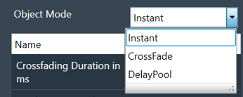
| Object Mode | Delay object operates in one of the following three modes.
m_Mode is used to specify whether the change in the delay is Instant or uses a Crossfade or operate as DelayPool. |
Mode
Delay object operates in one of the following three modes.
| Parameter | Description | Value | Data Type |
| Instant | No fading – change straight to the newly requested delay value. This is the default mode. | 0 (Instant) | uint |
| CrossFade | To avoid audio discontinuity when the delay value changes. | 1 (Crossfade) | uint |
| DelayPool | Max Delay determines the total DelayPool size which is common for all the channels. When the delay of individual channel is configured, the sum of delay values (of all the channels) can not exceed Max Delay. Changes in delay values are accepted by the audio object only when sum does not exceed Max Delay.
It does not support fading and no control inputs are added in this mode. When the sum of delay values exceeds the Max Delay and preset is applied in parameter-sets of GTT, then the UI may group some delay changes into one xTP command. This may cause audio objects to accept some delay value changes and reject other delay value changes. |
2 (DelayPool) | uint |
Additional Parameters
| Parameter | Description | |
| Crossfading Duration in ms | Fade time, only effective when the delay is operating in Crossfade mode.
|
 |
| Configuration Control Input(s) | Configuration control inputs (Enable/Disable).
|
 |
Tuning Parameters
| Parameter | Details | Default Value | Range | Data type |
| Delay | Delay to be applied across each channel | 0 (sec) | 0 – Max.delay (sec) | Float |
Control Parameters
| Parameter | Details | Default Value | Range | Data type |
| Delay(OneSet) | One control input is added to set the delay value for all audio channel to the same configured value. | 0 (sec) | 0 – Max.delay (sec) | Float |
| Delay(MultiSet) | One control input per channel is added to set the delay for individual channel. | 0 (sec) | 0 – Max.delay (sec) | Float |
2.1.1.Delay Panel
The Delay panel associated with Delay audio object. The Delay panel is used for changing the delay of the signal for each channel.

- Maximum / Minimum Delay Value: The maximum and minimum delay values are from corresponding state variable of Delay.
- Threshold Values: The maximum and minimum threshold values are derived from the GTT in the ParameterStore. Once the threshold value is reached, the Delay value bar will change to red color.
- Maximum threshold value: 95 %
- Minimum threshold value: Not set

- Changing Units: You can switch between the milliseconds, samples, centimeters.
|
Milliseconds
|
Samples
|
Centimeters
|
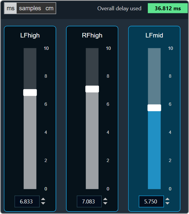


- Object Mode (Instant/CrossFade): In GTT the delay values are derived from the parameter store. Each channel’s delay value is configurable from 0 to Max Delay.
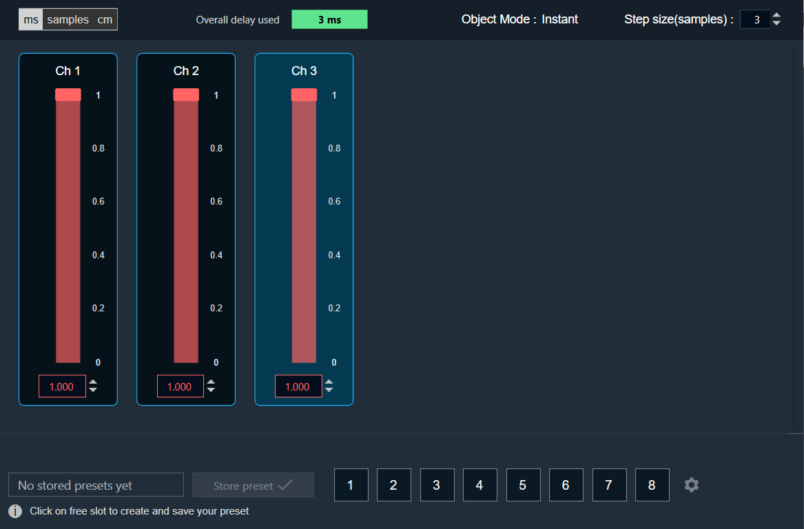
- Object Mode (DelayPool): In GTT the delay values are derived from the parameter store. When the object mode is set to DelayPool, the “Overall delay used” shown is sum of delay values of all the channels. Sum of the delay of channels is expected not to exceed Max Delay. Changes in delay values are accepted by the audio object only when sum does not exceed Max Delay.

You can find the overall “delay value used” at the top of the Delay panel. The value in text area changes its color depending on the percentage of the maximum overall delay value.
-
- Up to 80 % of the delay pool

- From 80 % – 100 % of the delay pool

- 100 % of the delay pool

- Up to 80 % of the delay pool
- Step Size for delay: In the application settings, you can change the global step size. The local step size in the delay audio object is derived from the global step size specified in the application settings. When you change the value of the local step size, the global step size value is no longer used.

To change the Delay Value
You can change the delay value in four ways:
- Using slider button: Select the slider to adjust the delay value.
- Using mouse scroll: Hover on the respective column and use mouse scroll to adjust the delay value.
- Using text box: Select the respective column and enter the dB value within the specified minimum and maximum range. Once you’ve entered the value, press Enter, and the slider will automatically adjust based on the input.
- Using the increase and decrease buttons
 the delay calculated step value (based on max delay (ms)).
2.2.Gain
The purpose of the Gain audio object is to provide amplitude scaling of the signal for each channel. The gain object also supports invert and mute feature.
Use Case: This object is deployed whenever a gain is required in the audio pipeline.
Gain Object Properties
Details about the Gain audio object properties and functionality.

| Properties | Descriptions |
| # of Channels | In the Signal Flow Designer (SFD), you can specify the maximum possible gain for the audio object. The number of channels is configurable in the SFD and is always equal to both, the number of input and output channels.
|
| Display Name | Display name of the gain audio object in signal flow design. It can be changed based on the intended usage of the object. |
Mode
There are no mode available for Gain audio object.
Additional Parameters
There are no additional parameters available for Gain audio object.
Tuning Parameters
The gain audio object supports in-place computation based on the core type.
The following are the paraments you can tune in to GTT.
| Parameter | Description | Unit | Range |
| Gain | Applied on the input channel. | dB | -128 to 20 |
| Invert |
|
None | 0 or 1 |
| Mute |
|
None | 0 or 1 |
Control Parameters
There are no control parameters available for Gain audio object.
2.2.1.Gain Panel
The Gain panel associated with Gain audio object. The Gain panel is used for changing the gain of a signal for each channel.
When you open a gain native panel, the Logarithmic scale is set to the default value. You can toggle option to switch between Linear and Logarithmic scale.
The gain values in the Logarithmic scale are rounded off to nearest next digit. For Linear scale values are retained as user entered.
- Logarithmic Scale: Gain values are displayed rounded to the nearest whole number.
Example:
If the gain value is -10.4 in Logarithmic scale it will be shown as -10.
If the gain value is -10.7 in Logarithmic scale it will be shown as -11.
All Gain panel functionalities are fully supported and work seamlessly when using the logarithmic scale.
- Linear Scale: Gain values are shown exactly as entered.
Example:
If the gain value is -10.8 in Linear scale it will be shown as -10.8.
On switching between these two options only scale is changed, State variable values and Tunning data remain same, Unless user changes the actual value.
When switching between logarithmic and linear scales, only the way gain values are displayed is affected. The underlying state variable values and tuning data remain unchanged unless you manually change the actual value.

- Maximum / Minimum Gain Value: The maximum and minimum gain values are from corresponding state variable of Gain.
- Maximum value: 20 dB
- Minimum value: – 120 dB
- Threshold Values: The maximum and minimum threshold values are derived from the ParameterStore in GTT. Once either of the threshold values is reached, the Gain value bar will change to the color red.

- In Phase / Invert: To invert or Inphase the gain value
- Click on the In Phase to invert the gain value.
- Click on the Inverted to in phase the gain value.
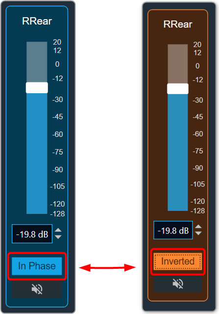
- Mute: The Mute button sets the gain value to a minimum gain value. Even if the gain value is muted, you can change it.

- Mute all: The Mute all button sets all gain values to minimum gain values. If all gains are muted, the Mute all button will change to Muted.
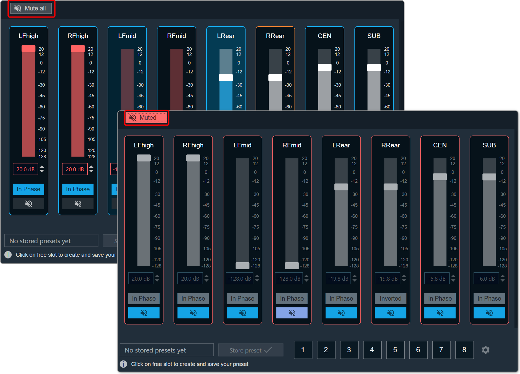
- Solo: The Solo button mutes all the channel except the selected one. Additionally, the phase of all the muted channels get disabled. Click on the Solo button again, to unmute all the channels.

To change the Gain value
You can change the gain value in four ways:
- Using slider button: Select the slider to adjust the value.
- Using mouse scroll: Hover on the respective column and use mouse scroll to adjust the value.
- Using text box: Select the respective column and enter the dB value within the specified minimum and maximum range. Once you’ve entered the value, press Enter, and the slider will automatically adjust based on the input.
- Using the increment and decrement buttons
 you can change the gain value.
2.3.Level Monitor
The Level Monitor is intended to measure the level of input; the audio samples are sent to the output without modification.
Use case: This object can be deployed in Level Monitor mode whenever there is a need to measure level of signal level and in Clip Meter mode to check if the level is causing clipping. The same input is sent as output without modification.
Level Monitor Properties
Below table describes about the Level Monitor audio object properties and functionality.

| Properties | Descriptions |
| # of Channels | In the Signal Flow Designer (SFD), the number of control outputs is equal to the number of audio channels. Each control output writes out the channel level/clip indication value based on the MODE selected.
|
| Display Name | Display name of the Level Monitor audio object in signal flow design. It can be changed based on the intended usage of the object. |
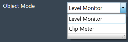
| Object Mode | During design time, the audio object channel can be configured in one of the two operation modes.
|
Mode
During design time, the audio object can be configured in one of the two operation modes.
- Level Monitor
- Clip Meter
| Mode | Description |
| Level Monitor |
This is the default mode. In this mode, the signal level is measured and the value is sent to the control output. |
| Clip Meter | In this mode, object computes the signal level and compares it with the threshold set through the tuning parameters. A flag is set / reset if the signal level is above / below the threshold and this flag is sent to the control output. |
Additional Parameters
There are no additional parameters available for Level Monitor audio object.
Tuning Parameters
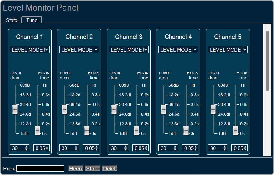
Under Level Monitor mode, following are the tuning parameters available for each channel.
| Parameter | Description | Range | Default | Data Type | Unit |
| LEV_MODE | To select the method of computation of input signal level
In all the above types, the computed level is always presented in dB (logarithmic scale) |
0 – RMS 1 – LINEAR 2 – PEAK |
0 | Float | NA |
| DB_LEAK_PER_SEC | Amount of dB drop per second in Peak Level mode. | 1 to 60 | 30 | Float | dB |
| PEAK_HOLD_TIME | Amount of time peak is held. | 0 to 1 | 0.05 | Float | second |
Under Clip Meter mode, following is the tuning parameter available for each channel.
| Parameter | Description | Range | Default | Data Type | Unit |
| Threshold | Threshold value for the channel to treat a signal as being clipped. | -20 to 20 | -0.25 | Float | dB |
State Parameters
Under Level Monitor mode, following is the state parameter available for each channel.
| Parameter | Description | Range | Default | Data Type | Unit |
| LEVEL_VALUE | Measured signal level for the channel | -128 to 20 | 0 | Float | dB |
Under Clip Meter mode, following is the state parameter available for each channel.
| Parameter | Description | Range | Default | Data Type | Unit |
| Clip Indicator | Clip Indicator for the channel based on the tuned threshold parameter | 0 or 1 | 0 | Unsigned Long | None |
Control Parameters
Under Level Monitor mode, following is the control output available for each channel.
| Parameter | Description | Range | Data Type | Unit |
| Signal Level | Measured signal level for the channel | -128 to 20 | Float | dB |
Under Clip Meter mode, following is the control output available for each channel.
| Parameter | Description | Range | Data Type | Unit |
| Clip Indicator | Clip Indicator per channel based on the tuned threshold parameter | 0 or 1 | Float | None |
2.3.1.Level Monitor Panel
Level monitor custom native panel can be used to visualize measurements and to tune measurement parameters, like types of level values. Panel shows as many channels as it is specified in SFD.
Level Monitor object has 2 working mode.
- Level Monitor: Level Monitor mode is used by engineers to measure level of volume in audio pipeline.
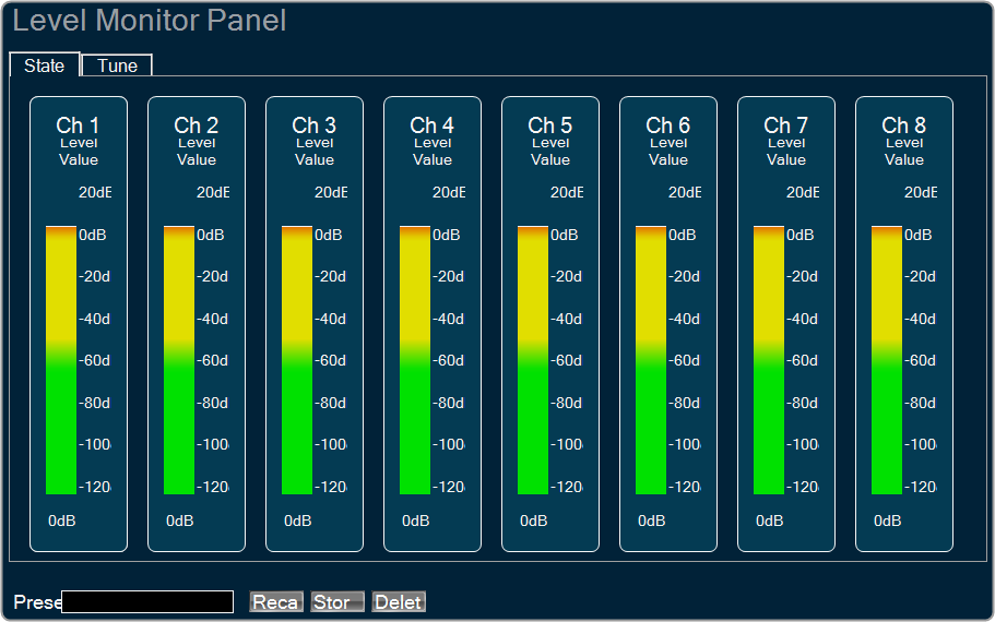
- Clip Meter: Clip Meter mode is used to check if the level is causing clipping.


State tab is used to show the level values or clipping indicators. This tab is read only.
Tune and custom tabs are used to adjust measurement parameters.
2.4.FaderBalance
The primary purpose of Fader Balancer audio object is to optimize the audio quality within the vehicle’s cabin by adjusting the sound distribution. Basically, this audio object allows to identify the “sweet spot” of the sound by moving in the x and y directions.
The Fader Balance object has only one operating mode and has three additional configuration parameters – Speaker Groups, Number of Steps, and Block Control. Using these additional parameters, you can configure the setup during design time.
Each audio channel may belong to one or two speaker group as set in the additional variable. Fader speaker group has the following speaker types:
- CENTER
- SIDE
- BASS
- FRONT
- REAR
Balance speaker group has the following speaker types:
- CENTER
- LEFT
- RIGHT
Each speaker type in each speaker group has its own gain table.
The output samples are generated by multiplying the input samples with the composite gain value that is a product of the gain levels of the Balance and Fader gain tables assigned to this channel and as pointed by the control inputs – Control_Balance and Control_Fader. The composite gain value is morphed to avoid pops.
Channel configuration (assignment to speaker types of the selected speaker groups), morphing time, and the gain level of each step are configurable through xTP interface. Basically, we are mixing run-time tuning (add cfg params) and design-time tuning (add cfg params). GTT is used for configuration in general, and xTP is the protocol used to deliver tuning data.
Fader and Balance positions are provided through control inputs.
Fader Balance is ported from the Summit version with the following differences:
- The option for 4 modes is not supported. This shall be handled with the preset files. The number of control inputs is brought down to 2 due to this change.
- Stand-alone Fader AO and Balance AO can be achieved by configuring the additional parameters in the SFD.
- The step count is made as an additional variable instead of using the “Number of Elements” field.
- The channel configuration is done using a drop-down menu to select only one speaker type in each speaker group. This prevents the selection of multiple speaker types by mistake.
Use Case: Using this method, you can optimize the sound loudness on the left or back of the cabin.
Fader Balance Properties
Below table describes about the Fader Balance audio object properties and functionality.

| Properties | Descriptions |
| # of Channels | The number of audio channels it can process is configurable in the SFD and ranges from 1 to 255. The number of audio inputs is always equal to the number of audio outputs.
|
| Display Name | Display name of the Fader Balance audio object in signal flow design. It can be changed based on the intended usage of the object. |
Mode
There are no mode available for Fader Balancer.
Additional Parameters
| Parameters | Description | |
| Speaker Groups | Speaker Groups can be set to one of the following three options:
|
 |
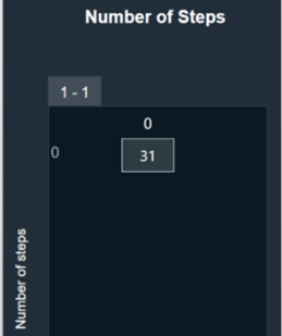
| Number of Steps |
The “Number of Steps” is a common variable that controls the number of gain levels that the user can operate. To control the gain level of fader and balance speakers the value shall be odd, and this value is common for balance and fader speaker groups. The number of steps need to be an odd number and shall range from 3 to 65 with the default value at 31. The xAF data order is set as “xAF_ODD” to communicate to the GTT through DDF to prevent entering even numbers by the user. |
 |
| Block Control |
Block Control Disabled (0) – Default Block Control Enabled (1) |
 |
Tuning Parameters
The following tuning parameters available for Fader Balancer audio object.
| Parameter Name | Description | Type | Unit | Default value |
| MorphingTime | Morphing time. The range is from 0 ms (no morphing) to 100 ms.
Morphing time follows time constant and the morphing time is denoted as M. Following is the percentage of change achieved: |
float | ms | 0.01 |
| Channel # Assignment | This parameter assigns particular audio channel to one or none of the speaker types in each group. The following pair of speaker type assignment is available for each channel.
|
ULong ULong |
— — |
BAL_CENTER FAD_CENTER |
| BalanceCenterTable |
Balance table for center speaker group. The gain value for each step is tunable. Range: -128 to 0 dB |
float |
dB |
0 |
| BalanceLeftTable |
Balance table for left speaker group. The gain value for each step is tunable. Range: -128 to 0 dB
|
float | dB | 0 dB for the first (NUMBER_OF_STEPS+1)/2 steps, next are linearly decreased with equal step in dB scale to -128 dB. |
| BalanceRightTable |
Balance table for right speaker group. The gain value for each step is tunable. Range: -128 to 0 dB |
float | dB | Start from -128 dB and are linearly increased with equal step in dB scale to 0dB to (NUMBER_OF_STEPS-1)/2 step, next their value is 0 dB. |
| FaderCenterTable | Fader table for center speaker group. The gain value for each step is tunable.Range: -128 to 0 dB | float | dB | 0 |
| FaderSideTable |
Fader table for side speaker group. The gain value for each step is tunable. Range: -128 to 0 dB |
float | dB | 0 |
| FaderBassTable | Fader table for bass speaker group. The gain value for each step is tunable.Range: -128 to 0 dB | float | dB | 0 |
| FaderFrontTable |
Fader table for front speaker group. The gain value for each step is tunable. Range: -128 to 0 dB |
float | dB | 0 dB for the first (NUMBER_OF_STEPS+1)/2 steps, next are linearly decreased with equal step in dB scale to -128 dB. |
| FaderRearTable |
Fader table for rear speaker group. The gain value for each step is tunable. Range: -128 to 0 dB |
float | dB | Start from -128 dB and are linearly increased with equal step in dB scale to 0dB to (NUMBER_OF_STEPS-1)/2 step, next their value is 0 dB. |
Control Parameters
The following two control parameters available for Fader Balancer audio object.
- Balance – To set the Balance knob position
- Fader – To set the Fader knob position
2.4.1.Fader Balance Panel
General tab
Basically, this audio object allows to identify the “sweet spot” of the sound by moving in the x and y directions. Using this method, you can optimize the sound loudness on the left or back of the cabin.
Used to map the channels to Balance Speaker group and Fader speaker group.

- Morphing time: The range is from 0 s (no morphing) to 0.1 s.
Morphing time follows time constant and the morphing time is denoted as M. Following is the percentage of change achieved:
– After M: 63%
– After 2M: 86%
– After 3M: 95%
– After 4M: 98%
– After 5M: 99%
Hence the morphing time can be configured accordingly.
The morphing time (through V release) is actually a time constant. Therefore if you want your morph 99+% complete in 100ms you should specify 20ms, not 100. One time constant will morph 63% of the way there.
- Channel assignment: Assigns a particular audio channel to one or none of the speaker types in each group.
- Balance Speaker Types: CENTER, LEFT & RIGHT
- Fader Speaker Types: CENTER, SIDE, BASS, FRONT & REAR
Fader tab
Used to control the gain level of fader in the range -128 to 0 dB.
- Front
- Center
- Side
- Rear
- Bass
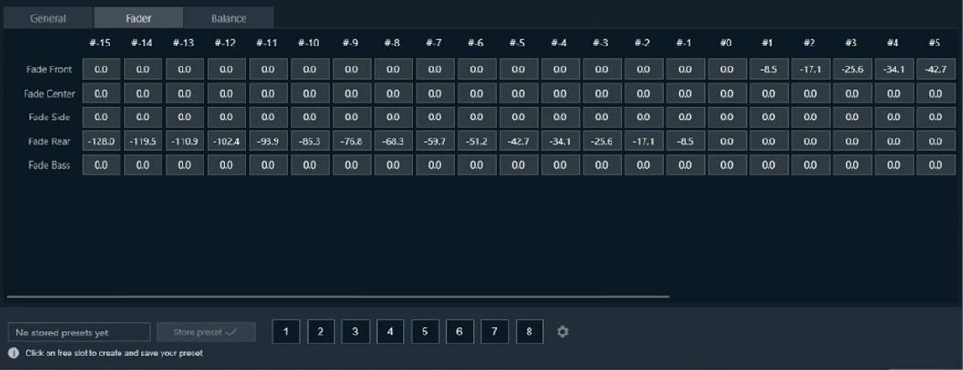
Balance tab
Used to control the gain level of balance in range -128 dB to 0 dB.
- Center
- Left
- Right

2.5.Volume and Mute
The purpose of the Volume and Mute audio object is to control the volume or mute in the audio pipeline. Additionally, Volume block also amplitude scaling with ramps.
Use a custom native panel to change the Volume and Mute audio object parameters. The mode and tune type may also be selected at design time from within SFD.
The Volume and Mute audio object supports in-place computation based on the core type.
Volume and Mute Properties
Below table describes about the Volume and Mute audio object properties and functionality.

| Properties | Descriptions |
| # of Channels | In SFD, the number of channels is specified, and the number of input channels is equal to the number of output channels.
|
| Display Name | Enter the display name of the audio object. It can be changed based on the intended usage of the object. |
| Object Mode | Volume object operates in one of the three modes.
|
Mode
Volume object operates in one of the three modes.
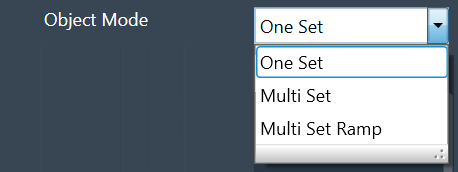
| Mode | Description |
| One Set | In this mode, the volume object exposes these six values.
These values are applied across all channels of the module. The ramping variables are only available via parameter tuning in this mode. |
| Multi Set: | In this mode, Volume, Mute, and Invert values are available per channel. One set of ramp rates and shape however is applied to all channels. The ramping variables are only available via parameter tuning. |
| Multi Set Ramp: | In this mode, Volume, Mute, Invert, Ramp Up rate, Ramp Down Rate, and Ramp shape values are all available per channel. |
Additional Parameters
Volume and Mute audio object consist of following additional parameters.
- Ramp Tuning Mode
- Boot State
- Boot Level
- Mute state on volume change
| Parameters | Description | |
| Ramp Tuning Mode | Ramping is applied when a transition or change occurs and is specified in terms of rate (ms/dB) or time (ms).
|
 |
| Boot State | The boot-up or start-up state of the Volume AO can be specified in 0 or 1.
|
 |
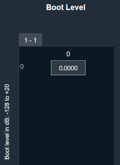
| Boot Level |
The amplitude level of the Volume AO at boot-up or start-up time can be specified. Range: -128 dB to + 20 dB The default value shall be 0 dB. |
 |
| Mute state on volume change | The desired state of the AO when the volume parameter is changed while the object is in Mute state is specified here.
|
 |
Tuning Parameters
Ramp Parameters: The Volume audio object exposes ramp rate/time settings that can be adjusted from GTT.
| Parameters | Descriptions | Range | Unit |
| Ramp Up Rate or Time | Ramp up rate in ms/dB or ramp time in ms. | 0 to 1000 | ms/dB or ms |
| Ramp Down Rate or Time | Ramp down rate in ms/dB or ramp time in ms. | 0 to 1000 | ms/dB or ms |
| Ramp Shape | The shape the volume will change according to once a volume or mute control is triggered. |
|
Volume Parameters: The Volume object has three state parameters volume, mute and invert (phase shift of 0 or 180) per channel.
This functionality is only triggered in the multi-set mode.
| Parameters | Descriptions | Range | Unit |
| Volume | Volume to be applied on all input channels | -128 to 20 | dB |
| Mute | Mute to be applied on all input channels | 0 or 1 | |
| Invert |
If set to 1, all input channels will be multiplied by -1 If set to 0, all input channels will be multiplied by 1 |
0 or 1 |
Dynamic Control
| Parameters | Descriptions | Range | Unit |
| Volume | Volume to be applied on all input channels | -128 to 20 | dB |
| Mute | Mute to be applied on all input channels | 0 or 1 |
Control Parameters
The Volume control is triggered whenever a control message is addressed to the audio object. The volume object has 2 control pins or indexes for Volume and Mute.
| Parameters | Descriptions | Range | Unit |
| Volume | Volume to be applied on all input channels | -128 to 20 | dB |
| Mute | Mute to be applied on all input channels |
|
2.5.1.Volume and Mute Panel
When engineers need to control the volume or mute settings in their audio pipeline, they utilize the Volume and Mute audio objects. To modify the parameters of these objects, a custom native panel is used.
Possible configuration and its effects are shown in the table below.
| Configuration | Effect |
|
| Mode | Tune and State | Ramp Characteristic |
| OneSet |
Volume , Mute, and Invert is common to all channels.
|
Ramping values is common to all channels.
|
| MultiSet |
Volume ,Mute and Invert is for each individual channels.
|
Ramping values is common to all channels.
|
| MultiSet Ramp |
Volume, Mute, and Invert and Ramping values is for each individual channels.
|
|


Based on the configuration, user interface of the panel can vary.
As a result of this fact, the user interface of the current panel also undergoes changes to accommodate all the controls necessary for handling the audio object configuration.
You can modify any available state variables.
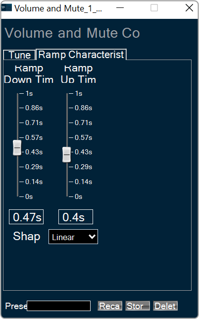
- To change volume, down or up ramp rate/time please use vertical faders or textboxes under them.
- To mute a specific channel in “Multi Set” modes or all channels in “Single Set” mode, simply click on the “Muted” or “Unmuted” button.
- To shift the phase of a specific channel in “Multi Set” modes or all channels in “Single Set” mode, click on the “In Phase or Inverted” button.
For ramping parameters, ramp shape can be set in one out of three shapes.
- Linear ramp shape
- Exponential ramp shape
- Jump ramp shape (volume increases immediately without any ramp shape)
2.6.VolumeLite
The purpose of the VolumeLite audio object is to control the volume in the audio pipeline. The VolumeLite audio object is light weight and different from “Volume Mute” AO. The object can alter the output volume by either attenuating or amplifying the audio.
This audio object supports ramping and each channel has its own set of – state variables as well as ramping parameters.
Use Case: The object can be used to control the volume of an audio channel.
VolumeLite Properties
Below table describes about the VolumeLite audio object properties and functionality.

| Properties | Description |
| # of Channels | In SFD, the number of channels is specified, and the number of input channels is equal to the number of output channels.
|
| Block Control | The object supports Block Control when the object is configured with more than one channel. It has one block control input which controls the output volume of which size is equal to the number of channels configured for the audio object. Block Control is enabled by default and cannot be disabled. |
Mode
There are no mode available for VolumeLite audio object.
Additional Parameters
| Parameter | Description |
|
| Boot Level |
It specifies the required volume level at boot time when configured. It is applicable for all the channels. Range: -128 dB to +20 dB. Default: 0 dB |
 |
Tuning Parameters
The following are the tuning parameters that can configure from GTT.
| Parameters | Description | Range | Default | Data Type |
| Ramp Up Time | Ramp up time in ms per channel. | 0 to 1000 ms | 5 ms | Float |
| Ramp Down Time | Ramp down time in ms per channel. | 0 to 1000 ms | 5 ms | Float |
| Ramp Shape | The shape of the volume will change accordingly once it is triggered and applies across all channels. |
|
Linear | ULong |
| Volume | Volume to be applied per input channel | -128 to 20 dB | 0 dB | Float |
All the channels can be tuned with one command as all are in the same subblock compared to Volume Mute object.
Control Parameters
The Volume control is triggered whenever a control message is addressed to the audio object. Block Control is deployed only when object has more than one channel. It has one block control input, the size of which is equal to the number of channels configured for the audio object.
| Parameters | Description | Range | Unit |
| Volume | Volume to be applied per input channel | -128 to 20 dB | dB |
Native Panel
The native panel for VolumeLite audio object is under development.
3.Control Objects
Control objects category contains following audio objects.
3.1.Control Math
The Control Math audio object provides the ability to manipulate input control signals.
Control Math Properties
Below table describes about the Control Math audio object properties and functionality.

| Properties | Description |
| Number of outputs/inputs | Enter the number of control outputs or inputs.
|
| Display Name | Display name of the control math audio object in signal flow design. It can be changed based on the intended usage of the object. |
| Object Mode | Control Math audio object supports twenty-six modes of operation. This audio object can be configured in the SFD to operate in one of the following modes:
Default object mode is set to Add. |
Mode
The Control Math audio object supports following modes.
| Mode | Description |
| ADD | In this mode, control inputs into the object are summed up and their sum is fed to the output of the object. |
| SUBTRACT | The difference between the first control input and the summation of the remaining control inputs into this object is sent out at the output. |
| MULTIPLY | Takes in input controls and writes their product to the output of the object. |
| DIVIDE | Takes 2 input controls and writes the result of their division to the output. If the divisor is zero, the result is set to the maximum float value. |
| MAXIMUM | Takes the input controls and writes out the maximum of the values. |
| MINIMUM | Takes in input controls and writes out the minimum of the values. |
| LIN2DB | Takes a linear control value as an input and outputs it’s logarithmic equivalent to the specific output pin. If the input is less than or equal to zero, the result is set to zero. |
| DB2LIN | Takes a logarithmic control value as an input and outputs it’s linear equivalent to the specific output pin. |
| INVERT | Reads in a control value and outputs the negative (inverse) of that value to the specific output pin. |
| RECIPROCAL | Takes in a value, x, and outputs its reciprocal (1/x). If the input value is zero, the result is set to the maximum float value to the specific output pin. |
| SQUARE | Takes in a value, x, and outputs its squared value to the specific output pin. |
| SQUAREROOT | Takes in an input value, x, and outputs its square root, . If the input is negative, the result is set to zero to the specific output pin. |
| AND | Takes in multiple inputs and outputs the logical AND operation of these inputs. |
| OR | Takes in multiple inputs and outputs the logical OR operation of these inputs. |
| XOR | Takes in multiple inputs (x1, x2, x3, xn) and outputs the logical XOR operation (((x1 xor x2) xor x3) xor xn) of these inputs. |
| NOT | Takes in an input, and outputs the NOT |
| NAND | Takes in multiple inputs (x1, x2, x3, xn) and outputs the logical NAND operation (((x1 nand x2) nand x3) nand xn) of these inputs. |
| NOR | Takes in multiple inputs (x1, x2, x3, xn) and outputs the logical NOR operation (((x1 nor x2) nor x3) nor xn) of these inputs. |
| GREATER | Takes in 2 inputs, and and outputs true if . |
| LESS | Takes in 2 inputs, and and outputs true if . |
| EQUAL | Takes in multiple inputs and outputs true if all the input values are equal. |
| SPLITTER | Takes in an input control and writes the output to a user specified number of output pins. |
| DUPLICATE | Takes in a user specified number of inputs and writes each input out to 2 output pins. |
| DELAY | Takes in a user setting delay (in ms) and writes out the output only after that delay time has passed. |
| NONLINEARCLIP | Takes in 3 inputs, x, min, and max.
|
| INDEX | It takes in multiple control inputs and outputs two control values.
In case of maximum or minimum values being the same, it returns the index of the first encounter. |
Additional Parameters
Control Math audio object supports additional configuration which allows to enabled or disabled Block Control. Which can be enabled or disabled by selecting between Block Control Disabled and Block Control Enabled. The object shall support Block Control in the following operating modes:
Block Control Enabled –
- Set “Object Mode” to EQUAL / AND / OR / NOR / NAND / XOR to enable the Block control, the number of input control pins can be grouped to one input block control pin.
- Set “Object Mode” to LIN2DB / DB2LIN /INVERT / RECIPROCAL / SQUARE / SQUAREROOT to enable the Block control, the number of input and output control pins can be grouped to one input block control pin and one output block control pin respectively.
By default, the Block Control function is disabled.
Tuning Parameters
There are no tuning parameters available for Control Math audio object.
Control Parameters
There are no control parameters available for Control Math audio object.
Native Panel
Control Math audio object does not support native panel.
3.2.Control Grouper
The Control Grouper audio object allows to merge two or more individual controls and combining them into a single output group, and then send as one signal output group to the connected object.
Use Case: The Control Grouper audio object is useful in context of the Block Control feature. When control signals are received from controlIn AO it will be received as individual control signals. If audio object needs all control signals together then control grouper can be used to combine the control signals.
Refer block control documentation for more details.
Control Grouper Properties
Below table describes about the Control Grouper audio object properties and functionality.

| Properties | Description |
| # of controls in Group |
Enter the number of control inputs. It is also the number of signals within the one group to control output. The number of control group output is always 1.
|
| Display Name | Display name of the Control Grouper audio object in signal flow design. It can be changed based on the intended usage of the object. |
| Object Mode | The audio object supports two modes of operations.
|
Mode
Control Grouper supports two modes.
- Send When All Received (Default mode)
- Send On Apply

| Mode | Description |
| Send When All Received |
In this mode Control Grouper AO does not send a control group output every time a control input is received. The Control Grouper AO waits till all the control inputs are received and then sends the control group output. If the control inputs are coming at a different rate, the object sends the control group output at the rate of the slowest incoming control input. |
| Send On Apply |
In this mode, Control Grouper AO has an additional “Apply” input pin. When input is received on apply pin, Control Grouper AO sends the group output. Control inputs have default values. These values are exposed as tuning parameters, these values can be modified using state variable explorer. These values are used, when one or more inputs are not received before the input on apply pin is received. |
Additional Parameters
There are no additional parameters available for Control Grouper audio object.
Tuning Parameters
There are no tuning parameters available for Control Grouper audio object.
Control Parameters
There are no control parameters available for Control Grouper audio object.
Native Panel
Control Grouper audio object does not support native panel.
3.3.Control GroupSplitter
The Control GroupSplitter audio object splits one control group input into multiple individual control outputs.
Use Case: This object can be deployed if user wants to split the block control to individual control signals which needs to be connected to different audio objects.
Control GrouperSplitter Properties
Below table describes about the Control GroupSplitter audio object properties and functionality.

| Properties | Description |
| # of controls in Group | Enter the number of control outputs. It is also the number of signals within the one group to control input.
The number of control group input is always 1.
The Control GroupSplitter audio object accepts a single block control at its input and splits it into a user-configurable number of single control outputs. |
| Display Name | Display name of the Control GrouperSplitter audio object in signal flow design. It can be changed based on the intended usage of the object. |
Mode
There are no mode available for Control GroupSplitter audio object.
Additional parameters
There are no additional parameters available for Control GroupSplitter audio object.
Tuning Parameters
There are no tuning parameters available for Control GroupSplitter audio object.
Control Parameters
The object always has N single control outputs. The number N is described via the number of elements variable in SFD. The object always has one group control input.
Native Panel
Control GroupSplitter audio object does not support native panel.
3.4.Control Multi Adder
The Control MultiAdder audio object provides the ability to manipulate input control signals. Refer description column of num elements for algorithm description.
Use Case: This object can be deployed whenever the addition of control inputs is required. Additionally, this object is used as the LUT Adder in Halosonic.
ControlMultiAdder Properties
Below table describes about the Control MultiAdder audio object audio object properties and functionality.

| Properties | Description |
| Number of Elements |
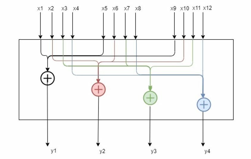
A minimum of three control inputs into the object are summed up and their sum is fed to the control output of the object. Each time the Control Multi Adder control input is set, it calls the corresponding control output. The object has 3 control inputs for elemental addition and forwards control value into an output.
Example: If the numElements is 4, there will be 4 control outputs [y1, y2, y3 and y4] and 12 control inputs [x1 to x12]. The control outputs are computed as shown in the figure below.
Maximum control inputs possible for a control multi adder instance are 255. For N elements specified from the configuration, 3N control input values would give N control output values. The number of control outputs is selected by numElements. The number of control inputs = 3 * numElements. The maximum number of control outputs is limited to 85, So the maximum number of control inputs is 85*3 = 255. |
| Display Name | Display name of the Control MultiAdder audio object in signal flow design. It can be changed based on the intended usage of the object. |

Mode
There are no mode available for Control MultiAdder audio object.
Additional parameters
There are no additional parameters available for Control MultiAdder audio object.
Tuning Parameters
There are no tuning parameters available for Control MultiAdder audio object.
Control Parameters
There are no control parameters available for Control MultiAdder audio object.
Native Panel
Control MultiAdder audio object does not support native panel.
3.5.Control Mixer
The Control Mixer audio object provides a mechanism to mix and route control signal from input to output. The mixer sums values from selected control inputs and pushes the sum to the output. Numbers of inputs and outputs are configurable via GTT. It enables N inputs to be connected to M outputs which is configurable ranging from 1 to 254. If there isn’t any input signal associated with output, the output wouldn’t be changed.
The non-weighted mode with one connected control input output channel. Connection can be changed from state variable window in GTT during tuning, but its impact will be visible once input at that control pins is changed.
It takes control signals as inputs and emits control signals as outputs. Many inputs can also be connected to one output and output can be left unconnected also. It can copy any input to arbitrary number of outputs (from 0 to number_of_outputs). It means that some inputs can be copied to multiple outputs, or some inputs can be cut (not used further in the pipeline). On the other hand, one output can have at most single input connected to it. Below picture illustrates the idea.

Control Mixer Properties
Below table describes about the Control Mixer audio object properties and functionality.

| Properties | Description |
| Display Name | Display name of the control mixer audio object in signal flow design. It can be changed based on the intended usage of the object. |
| Object Mode | Based on the weighing factor of the control inputs to be mixed, the Control Mixer works in two different modes.
|
Mode
The Control Mixer supports in two modes.
- Non-weight mixer(default)
- Weight mixer
Additional Parameter
| Parameter | Description | |
| Number of control input and output |
The max input and output in additional configuration is 100. Range: 1 to 254 The default number of control input and output pin is 1. |
 |
Tuning Parameters
There are no tuning parameters available for Control Mixer audio object.
Control Parameters
Default control input output is 1 and configurable through additional configuration from 1 to 254 (max).
3.5.1.Control Mixer Panel
The Control Mixer object supports native panel. The native panel window consists of rows and column. The number of row and column depends on “number of control inputs and outputs” configured.
In Non Weight Mode, table cells can have only two values 0 or 1.
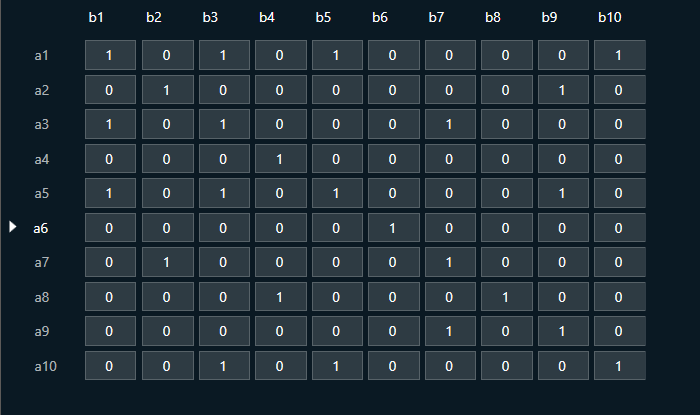
In Weight Mode, table cells can have values from 0 to 1.

Control Mixer supports copy-pasting values from and into Excel sheets.
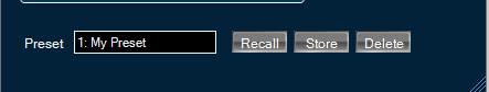
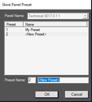
You can store the specific configuration and recalled via Store Preset option available on the panel. Configure the tuning parameters and select the free preset slot numbers, enter the name of the slot, and click Store preset. This saves and stores the current tuning data to the selected slot.
If you do not enter a name of the slot, then it will take the default named “New Preset”.
You can switch between presets slots and apply their values by simply clicking on them. Additionally, after clicking to override the preset, you can modify the tuning values in that tab or change the preset name.
To reset the selected preset or all the preset values.
- Click Reset Selected to clear the preset that is currently selected.
- Click Reset All to clear every preset in the corresponding native panel.

3.6.Control Router
The Control Router audio object provide a mechanism to route control signal from input to output. The router allows to change path of control signal during runtime, which allows for flexibility when designing audio signal pipeline.
This object can be deployed whenever different control inputs to be routed to an object.
It can have arbitrary number of inputs and outputs ranging from 1 to 254 and enables the inputs to be cut or copied to any number of outputs.
Control Router Properties

| Properties | Description |
| Display Name | Display name of the Control Router audio object in signal flow design. It can be changed based on the intended usage of the object. |
Mode
There are no mode available for Control Router audio object.
Additional Parameters
| Parameter | Description | |
| Number of control input and output |
The max input and output in additional configuration is 100. Range: 1 to 254 The default number of control input and output pin is 1. |
 |
Tuning Parameters
There are no tuning parameters available for Control Router audio object.
Control Parameters
Default control input output is 1 and configurable through additional configuration from 1 to 254 max.
3.6.1.Control Router Panel
The Control Router audio object supports native panel. The native panel window is a dynamic native panel. Panel get adapted in size based on the Router AO configuration.
By default, all outputs are disconnected.

Every output has an input that can be configured. More than one output can be assigned to a single input signal.
It is possible that some input signals are not assigned to any output.

Additionally, this panel enables to store presets for specific configuration.
Name of preset is configurable in separate window after click Store button:
3.7.Control Smooth
The Control Smooth audio object is used to smoothen the sharp changes in the control values before feeding them as control inputs to another AO. Sharp changes in the control value could cause artifacts in the audio output; in these situations, the Control Smooth audio object can be used to prevent artifacts.
For smoothening, this audio object uses a simple one pole filter that offers exponentially raising step response.
Use Case: This Control Smooth audio object can be used where there is a necessity to avoid drastic changes in control values that are fed as control inputs to an audio object. Below are a few examples:
- Interpolation between CAN updates.
- Control value smoothing to help avoid chatter in AO blocks with control thresholds or hysteresis (eg. gearshift simulator, steady state fade-out control, RNC control for vehicle speed ON/OFF control).
- Audio Objects that do not have support for ramping for change in control values.
Control Smooth Properties
Below table describes about the Control Smooth audio object properties and functionality.
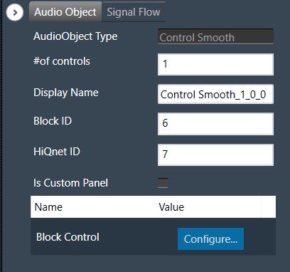
| Properties | Description |
| Number of Controls | Enter the number of control IO. The number of control inputs is same as the number of control outputs and the same is configurable via GTT.
|
| Display Name | Display name of the Control Smooth audio object in signal flow design. It can be changed based on the intended usage of the object. |
Mode
The Control Smooth object does not support any modes.
Additional Parameter
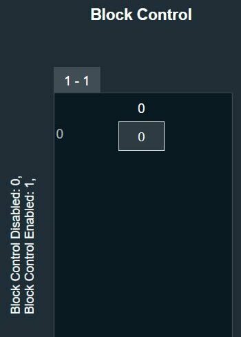
| Parameter | Description | |
| Block Control | This variable is used to enable or disable block control.
|
 |
Tuning Parameters
The object has the below three tuning parameters that are applicable for all the control inputs.
| Parameter | Description | Data Type | Range | Default | Unit |
| Bypass | The Control Smooth object functionality can be bypassed with this option | ULong |
0 – Bypass OFF 1 – Bypass ON |
0 | None |
| Smooth Time | Time taken by the smoothening filter to reach the target control value | Float | Block length duration to 10000 | Block length duration | ms |
| Hysteresis | The tolerance below or above which the filter starts adapting to new target value | Float | 0 to 100 | 0 | percent |
Control Parameters
Default number of control IO is 1 and configurable through the AO property – NumElements.
Native Panel
The Control Smooth object does not support native panel.
3.8.MultiStage Envelope
The MultiStage Envelope creates a control signal that changes over time in both deterministic and non-deterministic ways. It is a control-signal generator that generates a signal that changes over time by successively interpolating from one stage to the next, where each stage consists of a time and level pair.
It enables the randomization or adjustment of time, level, and curve shape within deterministic ranges. When the final stage is reached, it is possible to loop back to a specific segment.
MultiStage Envelope Properties
Below table describes about the MultiStage Envelope audio object properties and functionality.

| Properties | Description |
| No. of Steps |
Enter the number of stages or steps (nSteps). Multistage Envelope supports up to a maximum of 16 stages and looping back to any stage based on the configuration is allowed. So, the envelope generation can be continued in loop between stages. Time and level of each step is controlled by a fade parameter enabling the randomness and adjustments.
|
| Display Name | Display name of the MultiStage Envelope audio object in signal flow design. It can be changed based on the intended usage of the object. |
Below are the control input params:
- Reset
- Loop
- Shape
- Shape_Random
- Fader
- Fader_Random
First 6 of the Tuning params mentioned below are same as the control input params above. So, these 6 params can be controlled externally as well as internally.

Mode
There are no mode available for MultiStage Envelope audio object.
Additional Parameters
There are no additional parameters available for MultiStage Envelope audio object.
Tuning Parameters
The following are the parameters you can tune in GTT.
| Parameter | Data Type | Default Value | Range | Details |
| Reset | UInt | 0 | 0 to 2 |
|
| Loop | UInt | 0 | 0 to nSteps | Loop back to specified segment when last step is completed and continues envelope generation in loop when Loop is not 0. |
| Shape | Float | 0.0 | -1.0 to 1.0 | Specify shape or slope of envelope segments. The shape shall be varied in between the values.
|
| Shape_Random | Float | 0.0 | 0.0 to 1.0 | For a new random value to be created on start of each new segment, the value is added to SHAPE, and result is limited to [-1:1]. Full scale generated shape value will then be in the range [SHAPE_RND to SHAPE_RANDOM] |
| Fader | Float | 0.0 | 0.0 to 1.0 | Specify fade to linearly vary between levels/times. Pair of values of level and time is configured for each step. For each next level/time, the value is varied linearly between the pairs with FADER and FADER_RANDOM to get the target level/time. |
| Fader_Random | Float | 0.0 | 0.0 to 1.0 | For a new random value to be created on start of each new segment, the value is added to FADER and result is limited to [0:1]. Full scale generated fader value will then be in the range[-FADER_RANDOM to SHAPE_RANDOM] |
| OutScalFac | Float | 1.0 | -32767.0 to 32767.0 | Scale the envelope output level. This parameter is used to scale the envelope output range. By default, the env output range will be between 0.0 to 1.0. So, this param value is used to scale that value to a bigger range specified in the next column. |
| LevelMinValue | Float | 0.0 | -32767.0 to 32767.0 | Used to set lower value of envelope output range. By default, the env output range is between 0.0 to 1.0. The output envelope is scaled in range LevelMinValue and LevelMaxValue. |
| LevelMaxValue | Float | 1.0 | -32767.0 to 32767.0 | Used to set highest value of envelope output range. By default, the env output range will be between 0.0 to 1.0. The output envelope is scaled in range LevelMinValue and LevelMaxValue. |
| TimeA1 | Float | 100.0 ms | 1.0 to 10000.0 ms | First time value from the time pair of Step 1. The time duration to reach next step from Step1 is varied between TimeA1 and TimeB1. |
| TimeB1 | Float | 100.0 ms | 1.0 to 10000.0 ms | Second time value from the time pair of Step 1. The time duration to reach next step from Step1 is varied between TimeA1 and TimeB1. |
| LevelA1 | Float | 0.0 | 0.0 to 1.0 | First level value from the level pair of Step1. The source level of Step1 is varied between LevelA1 and LevelB1. |
| LevelB1 | Float | 0.0 | 0.0 to 1.0 | Second level value from the level pair of Step1. The source level of Step1 is varied between LevelA1 and LevelB1. |
| Shape1 | Float | 0.0 | -1.0 to 1.0 | This value determines the shape of the envelope from step1 to the next step. This value can be overridden by the 3rd tuning param, i.e. Shape which overwrites the shape of all steps. |
| TimeAN | Float | 100.0 ms | 1.0 to 10000.0 ms | First time value from the time pair of Step N. The time duration to reach next step from Step N is varied between TimeAN and TimeBN. |
| TimeBN | Float | 100.0 ms | 1.0 to 10000.0 ms | Second time value from the time pair of Step N. The time duration to reach next step from Step N is varied between TimeAN and TimeBN. |
| LevelAN | Float |
0.0 if N is odd 1.0 if N is even |
0.0 to 1.0 | First level value from the level pair of Step N. The source level of Step N is varied between LevelAN and LevelBN. |
| LevelBN | Float |
0.0 if N is odd 1.0 if N is even |
0.0 to 1.0 | Second level value from the level pair of Step N. The source level of Step N is varied between LevelAN and LevelBN. |
| ShapeN | Float | 0.0 | -1.0 to 1.0 |
Specify shape of the envelope between Step N and the next Step. This value can be overridden by the 3rd Tuning param, i.e. Shape, which is common for all the steps. |
State Parameters
| Parameter | Data Type | Default Value | Range | Notes |
| Envelope | Float | 0.0 | -32767.0 to 32767.0 | To stream the control output. This parameter is streamable. |
Control Parameters
The following are the control input parameters in GTT, there are 6 control inputs.
| Parameter | Description | Range |
| RESET |
RESET = 1: Reset the envelope generation from initial stage. RESET = 2: Deactivate envelope generation. Outputs last stage level value. RESET = 0: Do nothing |
0 or 2 |
| LOOP | Loop back to specified segment when last step is completed and continues envelope generation in loop. | 0 to nSteps |
| SHAPE | Specify shape or slope of envelope segments. The shape shall be varied in between the values.
|
-1.0 to 1.0 |
| SHAPE_RND |
For a new random value to be created on start of each new segment, the value is added to SHAPE and result limited to [-1:1] Full scale generated random value is in the range -SHAPE_RND…SHAPE_RND, |
0.0 to 1.0 |
| FADER | Specify fade to linearly vary between levels/times. Pair of values of level and time is configured for each step. For each next level/time, the value is varied linearly between the pairs with FADER and FADER_RND to get the target level/time. | 0.0 to 1.0 |
| FADER_RND | For a new random value to be created on start of each new segment. the value is added to FADER and result limited to [0:1] Full scale generated random value is in the range 0…FADER_RND, | 0.0 to 1.0 |
Illustration
The below diagram shows four 8-stage envelopes obtained from different settings of Time, Level and Shape. Each color-coding describes envelopes obtained from different runs of the algorithm.

For Example, settings of orange color envelope are show below.
- nSteps = 8
- So, Time and Level pairs will be: TimeA1,TimeB1,LevelA1,LevelB1,…,TimeA8,TimeB8,LevelA8,LevelB8
- TimeA1=30ms, TimeB1=30ms
- TimeA2=20ms, TimeB2=100ms
- Fader=1.0
- Fader_Random=0.0
- LevelA1=0.8, LevelB1=0.8
- LevelA2=0.1, LevelB2=0.03
To scale envelope output tuning parameter “LevelMinValue” and “LevelMaxValue” are used. There is no restriction added for “LevelMinValue” to be lower than “LevelMaxValue” in Tuning. It is required to set “LevelMinValue” to be smaller than “LevelMaxValue”. User can choose the values as per requirement of envelope output scaling.
Linear regrssion is used to scale the envelope output. Below is formula used for scaling the output.
outValue = LevelMinValue + (LevelMaxValue – LevelMinValue)*stepLevelValue
if want to scale level value from 0 to 1 to -128 to 128 LevelMinValue and LevelMaxValue value used should be
LevelMinValue = -128
LevelMaxValue = 128
Native Panel
MultiStage Envelope audio object does not support native panel.
3.9.AudioToControl
The AudioToControl audio object receives audio data, it calculates the envelope based on the mode of operation (either RMS or Peak) and forwards them onto control outputs.
This object accepts N number of input audio signals and calculates the envelope and sends them into corresponding control outputs.
Below are the features of AudioToControl audio object.
- The control outputs / state values are in linear scale.
- The AO supports all sample rates and blocklengths supported by xAF. The AO only reads the audio samples for calculating RMS or peak values. The AO supports in-place computation.
AudioToControl Properties
Below table describes about the AudioToControl audio object properties and functionality.

| Properties | Description |
| # of Channels | Enter the number of channels. The number of control outputs are equal to number of channels. This audio object operates in RMS and Peak modes.
|
| Display Name | Display name of the AudioToControl audio object in signal flow design. It can be changed based on the intended usage of the object. |
| Object Mode | This audio object works in two modes.
|
Mode
- RMS: The RMS value of input audio channels are calculated and sent out in corresponding control out channel.
- Peak: The Peak value of input audio channels are calculated and sent out in corresponding control out channel.
Additional Parameters
There are no additional parameters available for AudioToControl audio object.
Tuning Parameters
It has tunable parameters attack and release time. Attack and release time are common for all channels.
| Parameter | Data Format | Memory Offset | Unit | Range | Default Value |
| Attack time | float | 0 | Msec | 0 to 1000 | 100 |
| Release time | Float | 4 | Msec | 0 to 1000 | 10 |
The AudioToControl audio object has state parameters envelope value for all channels, rate attack and rate release. The states are read-only.
| Parameter | Data Format | Memory Offset | Unit | Range | Default Value |
| Channel 1 envelope | Float | 0 | None | – 9999 to 9999 | None |
| Channel 2 envelope | Float | 4 | None | – 9999 to 9999 | None |
| Channel N envelope | Float | (N – 1) * 4 | None | – 9999 to 9999 | None |
Control Parameters
There are no control inputs. The number of control outputs is always equal to the number of audio inputs.
Native Panel
AudioToControl audio object does not support native panel.
3.10.Lookup Table (LUT)
The Lookup Table (LUT) audio object performs a table lookup to create a relationship between a control input and a control output.
For example, The LUT converts vehicle speed value to gain by manipulating the speed values using a look up table. LUT module interpolates values of multiple 1-D functions (i.e. control outputs) at specific query points using ‘linear’ or ‘none’ interpolation.
The number of columns in the LUT is configurable by modifying the number of control outputs from the SFD. The first column of the table contains one independent vector which corresponds to the x axis of the interpolation. Each of the corresponding columns corresponds to the interpolation slopes for the outputs. The number of rows of LUT denote the number of steps in interpolation of each control output.

The LUT performs linear interpolation between values.
- If the control input is below the minimum value in the x- axis, the LUT will output the minimum value in the table.
- If the control output is above the maximum value, the output is limited to the maximum value in the table.
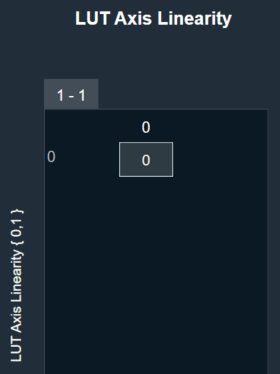
The LUT supports Axis Linearity and when enabled, LUT optimizes interpolation and assumes equally spaced steps of interpolation i.e., x-axis interpolation.
- If ‘Linear’ Interpolation (interpolation type = 1) is selected and the control input has value between two rows, then it is manipulated to create the control output vector.
- If ‘None’ (interpolation type = 2) is selected and the control input has value between two rows, then control output is the previous known control output. This follows for the other control inputs.
LUT Axis linearity is to be used with linearly spaced axis values.
Every time the LUT receives an input on its control pin, it will output on each control pin output (one per element).
Currently, the LUT is a series of dimensional tables of resolutions from 2-200. The number of elements corresponds to the number of columns. The table resolution on columns is configurable by modifying the first additional variable ‘Table Height’. Both the dependent and independent table values are configurable in the GTT. The x-axis (control-input) needs to be in ascending order and is configurable through the tuning tool.
Lookup Table Properties
Below table describes about the Lookup Table (LUT) audio object properties and functionality.

| Properties | Description |
| Number of elements | Enter the number of channels.
|
| Display Name | Display name of the LUT audio object in signal flow design. It can be changed based on the intended usage of the object. |
| Object Mode | LUT works in two modes.
|
Mode
LUT audio object is used to manipulate some control input to pass to one or multiple connected objects. The object operates in two modes.
| Mode | Description |
| LUT 2d |
In the 2D mode, there is one control input, and the number of outputs varies based on the number of elements selected. The objective of this LUT mode is to take in a control input, such as vehicle speed, and interpolate an output value, such as gain, based on values set during tuning. The output is then sent as input to other audio blocks. Primary Success Scenario
|
| LUT Index |
In the Index mode, there is a second control input. This control input selects which ‘set’ of tables to use. Otherwise the modes behave the same. The number of sets is configured by the additional variable ‘LUT Depth’. The maximum depth is 8. The objective of this mode of LUT operation is to determine output given an indexed set of tables.
|
Additional Parameters
Following are additional parameters you can configure, for more details refer to Additional Parameters.
- Table Height
- UNUSED_VAR
- LUT Axis Linearity
- LUT Depth
- Interpolation Type
- Block Control
- Group
| Parameter | Description | |
| Table Height | This parameter corresponds to the size of each table in linear steps which can be configured through an additional configuration variable.
|
 |
| UNUSED_VAR | This parameter is used to configure old variable through an additional configuration variable which is used to control how values were ramped outside of table ranges. |  |
| LUT Axis Linearity |
This parameter is used to set the manipulation logic for interpolation through an additional configuration variable. Manipulation logic
|
 |
| LUT Depth | This parameter is used to determine the depth of the table which can be configured through an additional configuration variable.
|
 |
| Interpolation Type | This parameter supports one additional configuration of Interpolation type which decides the type of interpolation for values on the output axis. This decides how output is computed for an input value that is between two given input axis values.
|
 |
| Block Control |
This parameter supports additional configuration of Block Control which can be enabled or disabled by selecting between Block Control Disabled (default) and Block Control Enabled. If it is enabled, all the control output signals are grouped into one control pin.
|
 |
| Group |
The Group feature allows organizing the LUT audio objects into different groups. When the native panel of any LUT audio object is opened, all the LUT audio objects with the same group name are displayed in that native panel. If no LUT objects are assigned to any group, native panel displays all the LUT audio objects. |
|
Tuning Parameters
The total number of tuning parameters depends on the LUT table height, table depth, and number of elements; which specifies the number of dependent output values and is equal to the number of columns in the LUT parameter table.
Hence, the number of elements = number of control outputs = number of LUT table columns.
In the LUT table, there is also an additional column for ‘LUT Index’ mode, which stores the values of x-axis interpolation points. As a result, the total number of elements in the LUT’s parameter memory is as follows.
| Parameter | Description | Data Type | Range | Unit |
| m_Params for ‘LUT 2D’ mode | Total tuning parameters = (NUM_ELEMENTS+1) * TableHeight | Float | -99999.0 to 99999.0 | None |
| m_Params for ‘LUT Index’ mode | Total tuning parameters = (NUM_ELEMENTS+1) * TableHeight * TableDepth | Float | -99999.0 to 99999.0 | None |
Control Parameters
There are one or two control input values for LUT based on the mode selected.
- LUT 2D: 1 float word
- LUT Index: 2 float words
The first corresponds to the value that needs to be converted to control output. The second determines which table index to use for interpolation.
| Name | Description | Data Type | Range | Unit |
| m_states [0] | Corresponds to the control input value that needs to be modified. | Float | -32768.0 to 32767.0 | None |
| m_states [1] | Determines which table index to use for interpolation. | Float | 1.0 to 8.0 | None |
Create LUT Object
- Load xAF DLL in GTT that supports LUT.
- Open the Signal Flow Designer.
- Drag and drop LUT audio object into the Signal flow design view.

- Verify the object is created with no error messages.
The properties and compare to these defaults.
The additional variables below are not actually object variables, they only belong to the GUI object are not covered by this document. See GTT documentation for further information.
| AudioObject Properties | Additional Variables | ||
| number of elements | 1 | Table Height | 2 |
| Object Mode | LUT 2D | UNUSED_VAR | 0 |
| LUT Axis Linearity | 0 | ||
| LUT Depth | 1 | ||
| Interpolation type | 1 | ||
| Block Control | 0 | ||
Create LUT Object in Mode 0 (LUT 2D)
- The object should already be in mode 0 (LUT 2D).
- Verify there is one control input and one control output. Change the number of elements to three.
- Verify the object now has three control outputs.

Create LUT Object in Mode 1 (LUT Index)
- Change the object mode to LUT Index.
- Verify the object now has two control inputs.
- Change the number of elements to six.
- Verify the object now has six control outputs.

3.10.1.Lookup Table (LUT) Panel
LUT object supports native panel. The native panel window consists of the options to enter the values.
To open the native panel, double-click on the LUT object in the SFD. Set the values accordingly.

4.1.Router
The Router audio object routes any of the input channel to any output channel without changing samples of the source. Additionally, you can route the same input channel to multiple output channels.
In the SFD, you can select the values that they prefer for “# Input channels” and “# Output channels”. These values can be distinct.
Use Case: This object can be deployed whenever each output channel is routed to any one of the input channels.
Router Properties
Below table describes about the Router audio object properties and functionality.

| Properties | Description |
| # of Audio In | Enter the number of input channels.
|
| # of Audio Out | Enter the number of output channels.
|
| Display Name | Display the name of the Router audio object in signal flow design. It can be changed based on the intended usage of the object. |
| Object Mode | Router object operates in one of the following two modes.
|
Mode
Router object supports two different modes of operation. After selecting the router object in GTT, one can configure the modes as described below.
By default, the router object is configured to operate in the Jump mode.
- Jump: In this mode, the object performs the tuning or routing without any ramping and switches the input to output routing between two calc calls. This might cause clicks and pops if no fading or mute stage is performed on an instance or core level.
- Ramping: In this mode, the object will perform a ramping while changing the input to output routing. In addition to the routing parameters this mode supports a tuning of the ramp time in the range of 0 to 5 seconds.
Presently, the object supports only linear ramping. The ramping type is not configurable.
If the router is configured with six input and six output channels, the tuning parameters will be displayed in GTT as shown below.

Additional Parameters
There are no additional parameters available for Router audio object.
Tuning Parameters
Below table describes the tuning parameters of Router audio object.
| Parameter | Description | Unit | Data Type | Default | Range |
| Router |
Each output channel has this parameter to configure the Input channel number to route to the particular output channel. This parameter is available in both modes. |
None | ULong | 1 | 1 to Number of Audio Inputs |
| RampTime | Ramping time
This parameter is available only in Ramping mode |
Seconds | Float | 0.5 | 0 to 5 |
Control Parameters
There are no control parameters available for Router audio object.
4.1.1.Router Panel
Router panel is a dynamic native panel. Panel get adapted in size based on the Router AO configuration.
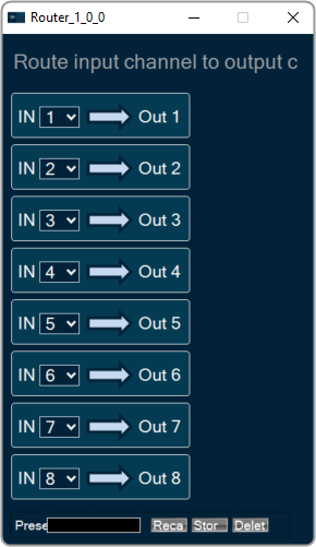
4.2.Splitter
The Splitter audio object copies the samples of one input channel to multiple output channels.
Use Case: This object can be deployed whenever an input channel to an object is required to be replicated to multiple channels at the output.
Splitter Properties
Below table describes about the Splitter audio object properties and functionality.
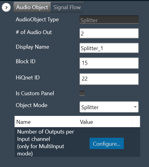

| Properties | Description |
|
# of Audio Out # of Audio In |
In Splitter, the number of input and output channels depends on the selection of object mode. – # of Audio Out: When the object mode set as “Splitter”, you can configure number of the output channel in the “# of Audio Out” field.
# of Audio Out is the default configuration. – # of Audio In: When the object mode set as “MultiInput”, you can configure number of the input channel in the “# of Audio In” field as per below range.
|
| Display Name | Display the name of the Splitter audio object in signal flow design. It can be changed based on the intended usage of the object. |
| Object Mode | The audio object channel can be configured in one of the two operation modes.
|
Mode
Splitter object operates in one of the two modes.
- Splitter
- MultiInput
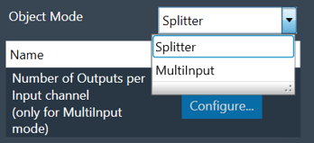
| Mode | Description |
| Splitter | The purpose of Splitter mode is to copy the input audio data N times to the output buffers. In this mode you can set the number of output channels and number of input channel is always fixed to one. The object replicates the single input channel to all output channels of the object. This is the default mode. The additional parameter “Number of Outputs per Input channel” is not supported in Splitter mode. |
| MultiInput | The purpose of the MultiInput mode is to use one instance of the audio object instead of instantiating it N times if you have N channels. The number of output channels equals the number of audio inputs multiplied by the value entered in the additional configuration variable “Number of Outputs per Input channel”. The maximum number of audio outputs is determined by the number of inputs, as number of output channel per object cannot exceed 255. It splits multiple signals the same number of times. The number of copies of each input channel produced at the output is determined by the value set in the additional configuration variable.  |
Additional Parameters
| Parameters | Description | |
| Number of Outputs per Input channel | The object has an additional configuration variable “Number of Outputs per Input channel” for MultiInput mode. It denotes the number of copies of each input channel. It is configurable between 2 to (255/Number of Audio Inputs).For example, if number of audio inputs are set to 25. Then the “Number of Outputs per Input channel” value is configurable between 2 to 10 as the maximum number of output channels supported cannot exceed 255. Default : 2 |
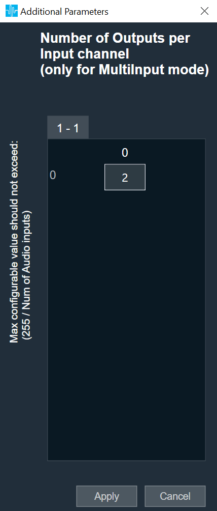 |
Tuning Parameters
There are no tuning parameters available for the Splitter audio object.
Control Parameters
There are no control parameters available for the Splitter audio object.
Native Panel
Splitter audio object does not support a native panel.
4.3.Demux
The Demux audio object routes input channel samples to any one of the output channels without any change in sample values whereas the rest of the output channels have zero values.
This audio object has a single input audio buffer and several output buffers. The number of output channels is configurable in the SFD.
The Demux object always has one variable that the GTT can access, and that variable is the one that determines which output channel the input should be written.
Use Case: This object can be deployed whenever an input channel to an object is required to be routed to one specific output channel (selected via tuning).
Demux Properties
Below table describes about the Demux audio object properties and functionality.

| Properties | Description |
| # of Audio Out | Enter the number of output channels. Based on a tuning variable, it selects the output where the input should be sent. Only one of the Demux audio objects output channels will have data at any one time.
The Demux object always has 1 input channel. |
| Display Name | Display the name of the Demux audio object in signal flow design. It can be changed based on the intended usage of the object. |
Mode
There are no mode available for Demux audio object.
Additional Parameters
There are no additional parameters available for Demux audio object.
Tuning Parameters
Below table describes the tuning parameters of Demux audio object.
| Parameter | Description | Data type | Unit | Default | Range |
| Demux_Ch | Output channel index to route the input to (starting from channel index 1) | Unsigned Long | None | 1 | 1 to Number of output channels |
Control Parameters
There are no control parameters available for Demux audio object.
Native Panel
Demux audio object does not support native panel
4.4.Selector
The Selector audio object allows you to switches between two sets of consecutive input channels and routes one of the sets to the output. While switching between the two sets, it applies ramping.
The Selector object has user configurable number of outputs which would imply that the number of inputs would be twice the output channels. The first n channels would be first group and n+1 to 2n channels would be next group.
For example: If the output configured is 2, then number of inputs would be 4. There would be 2 groups. 1 and 2 channels would form first group, 3 and 4 channels would be next group. The 2 output channels would be routed either from group 1 or group 2 based on selection.
Use case: This object can be deployed whenever a selected input channels are required in output channels in the audio pipeline.
Selector Properties
Below table describes about the Selector audio object properties and functionality.

| Properties | Description |
| # of Audio Out | Enter the number of output channels.
The number of inputs are always twice the number of output channels. |
| Display Name | Display the name of the Selector audio object in signal flow design. It can be changed based on the intended usage of the object. |
Mode
There are no mode available for Selector audio object.
Additional Parameters
There are no additional parameters available for Selector audio object.
Tuning Parameters
Below table describes the tuning parameters of Selector audio object.
The object exposes one variable for tuning, which is the ramp time.
| Parameter | Description | Type | Unit | Default | Range |
| Ramp time | The selected input channels are available at output channels within ramp time. | float | ms | 1 ms | 0 to 10000 |
| Selector Control | The object also has tuning parameter SelectorControl for switching between two groups. | Unsigned Long | None | 0 |
0 – channel 1 to m_NumAudioOut 1 – channel m_NumAudioOut +1 to m_NumAudioIn |
Control Parameters
The Selector exposes one control, which is the actual switch that triggers switching between the two sets. Below table describes the control parameters of Selector audio object.
| Parameter | Description | Type | Unit | Default | Range |
| selector Val | This is the actual switch that triggers switching between the input groups similar to SelectorControl of tuning parameter. | unsigned integer | None | 0 |
0 – channel 1 to m_NumAudioOut 1 – channel m_NumAudioOut +1 to m_NumAudioIn |
Native Panel
Selector audio object does not support native panel.
5.Source Objects
Source objects category contains following audio objects.
5.1.Noise Generator
The Noise Generator audio object generates noise audio samples scaled by a specified gain value.
Use Case: This object can be deployed to generate noise of different types with different gain values.
Noise Generator Properties
Below table describes about the Noise Generator audio object properties and functionality.

| Properties | Description |
| # of Audio Out | Enter the number of output channels.
|
| Display Name | Display the name of the Noise Generator audio object in signal flow design. It can be changed based on the intended usage of the object. |
| Object Mode | Noise generator operates in one of the following two modes.
|
Mode
The Noise generator object supports four different modes of operation.
| Mode | Description |
| White Noise (Mode 0) | The White noise is generated based on the initial seed value. The initial seed value is multiplied by a scale factor to get white noise. This is the default mode. |
| Pink Noise (Mode 1) | To generate pink noise, white noise is generated first and pink filter is applied over that. |
| Pro-Prbs (Mode 2) | The Pro-Prbs (Pseudo Random Bit Sequence) mode generates white and pink noise that can be chosen through tuning parameter.
|
| Pro-Lcg (Mode 3) | The Pro-Lcg (Linear Congruential Generator) mode generates white and pink noise that can be chosen through tuning parameter.
|
In all the modes, the gain (Noise Level) is in dB scale ranging from -128 dB to 0 dB. The same gain value applies to all channels of the Noise Generator object. It also exposes that same variable for control purposes.
Additional Parameters
There are no additional parameters available for Noise Generator audio object .
Tuning Parameters
Below table describes the tuning parameters of Noise Generator audio object.
For White Noise and Pink Noise mode
| Parameter | Description | Unit | Data Type | Default | Range |
| Noise Level | Generates noise in output channel with gain as tuneable. | db | Float | -60 | -128 to 0 |
For Pro-Prbs and Pro-Lcg modes
| Parameter | Description | Unit | Data Type | Default | Range |
| Noise Level | Generates noise in output channel with gain as tuneable. | db | Float | -100 | -128 to 0 |
| Noise Type | Generates white or pink noise in output channel with noise type as a tuneable parameter. This is applicable only for Mode 2 (Pro-Prbs) and Mode 3 (Pro-Lcg).The noise type parameter allows the user to choose white noise or pink noise dynamically. |
None | Float | 1 |
0 (White) or 1 (Pink) |
Control Parameters
The Noise Generator object has one control input – Gain (Noise Level) ranging from -128 dB to 0 dB and this value is applicable to all the channels. This control input is available in all the four modes.
This audio object does not have any control output.
5.1.1.Noise Generator Panel
The Noise Generator Panel is used to change noise type and noise level. In SFD you can configure several output channels. The same noise type and level will be applied to each channel.
Noise Generator panel works only with PRO object modes “Pro-Prbs” and “Pro-Lcg”. Panel will not work in “WhiteNoise” and “PinkNoise” object modes.

Changing Noise Level
You can change the noise level by three ways:
- Using slider button: Select the slider to adjust the value.
- Using mouse scroll: Use mouse scroll to adjust the value.
- Enter an exact value in the text box.
Changes will take place after hitting the “Enter” key or by moving the focus away from the text box.
Changing Noise Type
You can change the noise type by clicking on the combo-box and selecting the type.
Possible noise generator types are:
- White Noise
- Pink Noise
5.2.Wave Generator
The Wave Generator audio object generates the sine tone for a given frequency and gain depending on control pins. This audio object has either no input or one input channel. It has one output channel and two control pins.
Use case: The purpose of Wave Generator audio object is to generate sine waves for a specified frequency and gain in Signal Flow Designer, mostly to test the speakers.
Wave Generator Properties
Below table describes about the Wave Generator audio object properties and functionality.

| Properties | Description |
| Display Name | Display the name of the Wave Generator audio object in signal flow design. It can be changed based on the intended usage of the object. |
| Object Mode | Wave generator objects operate in one of the following two modes.
|
Mode
The Wave Generator object supports three different modes of operation.
| Mode | Description |
| Sine – Without Input |
This mode generates sine wave signal for specified frequency and gain. This is the default mode. |
| Sine – With Input | This mode generates sine wave signal for specified frequency and gain and mixes the generated signal with input signal. This mode is used for cascading sines. |
| Sweep | This mode generates frequency sweep signal for specified start and end frequency, gain, sweep time, sweep type, and loop type. |
Additional Parameters
There are no additional parameters available for Wave Generator audio object.
Tuning Parameters
Below table describes the tuning parameters of Wave Generator audio object.
| Mode | Parameter | Description | Unit | Data Type | Range | Default |
| Sine – Without input | Bypass | The generator is turned ON(0)/OFF(1) | None | ULong | 0 or 1 | 0 |
| Gain | Gain of generated signal | dB | Float | -128 to 0 | -128 | |
| Frequency | Frequency of generated signal | Hz | Float | 0 to 20000 | 0 | |
| Sine – With input | Bypass | The generator is turned ON(0)/OFF(1) | None | ULong | 0 or 1 | 0 |
| Gain | Gain of generated signal | dB | Float | -128 to 0 | -128 | |
| Frequency | Frequency of generated signal | Hz | Float | 0 to 20000 | 0.0 | |
| Sweep | StartFreq | Start frequency of sweep signal to be generated | Hz | Float | 20 to 20000 | 20 |
| EndFreq | End frequency of sweep signal to be generated | Hz | Float | 20 to 20000 | 20000 | |
| SweepTime | Duration of sweep | s | Float | 0.1 to 20 | 2 | |
| Gain | Gain of generated signal | dB | Float | -120 to 20 | -20 | |
| SweepMethod | Type of frequency sweep.
|
None | Signed Integer |
0 – Logarithmic 1 – Linear |
0 | |
| LoopType | Type of looping/repetition of the signal after “SweepTime”. The loop type can be
|
None | Signed Integer |
0 – None 1 – START_TO_ END 2 – WARBLE |
0 |
Control Parameters
Below table describes the control parameters of Wave Generator audio object.
| Mode | Parameter | Description | Unit | Range |
| Sine – Without input | Frequency | Frequency of generated signal | Hz | 0 to 20,000 |
| Gain | Gain of generated signal | dB | -128 to 0 | |
| Active |
When transition from high to low (Inactive): Completes the signal generation until zero cross over and mute the output and mute input signal for object mode Sine – with input. When transition from low to high (Active): Reset phase of the signal and signal generation is active and unmute input signal for object mode Sine – with input. |
None | 0 to 1 | |
| Sine – With input | Frequency | Frequency of generated signal | Hz | 0 to 20,000 |
| Gain | Gain of generated signal | dB | -128 to 0 | |
| Active |
When transition from high to low (Inactive): Completes the signal generation until zero cross over and mute the output and mute input signal for object mode Sine – with input. When transition from low to high (Active): Reset phase of the signal and signal generation is active and unmute input signal for object mode Sine – with input. |
0 to 1 |
There are no control inputs in ‘Sweep’ mode.
There are no control outputs for this audio object.
Native Panel
Wave Generator object t does not support native panel.
5.3.DC Generator
This Audio Object generates DC signal with the amplitude specified in the tuning parameter or the control input. The output amplitude is a floating point value that ranges from -1.0 to +1.0.
The object is not configurable during design time and always generates only one output. The object has one tuning parameter (outputAmp) and one control input (Sets output amplitude) and both of them are used to vary the DC output amplitude.
The object does not have any audio input or control outputs.
5.4.FilePlayer
The FilePlayer audio object is used to read the audio content from a file and present them in real time on the output channels. Additionally, this audio object can also be used to add or mix the file content with the audio fed into the input channel buffers of this object.
A background thread is used to read the file contents in bulk and place them in the intermediate cache buffer, while in the main thread for each audio interrupt, the required audio data (of framework block length size) is copied from the intermediate cache buffer to the output channel buffers. The background thread periodically checks for the number of samples available in the cache buffer and replenishes the needed files.
Use Case: The FilePlayer has following use case.
- Stream wav files from local filesystem in realtime
- Resample to target sample rate if needed
- Option to support play speed from 0.1 to 10
- Shall support option to disable / enable pitch shifting (linear and polyphase)
- Shall support mixing the file content with the output of another AO
- Support configurable number of output channels (up to 16)
- Support WAV / PCM Files configurable during design time. Furthermore, WAV / PCM files with all of these data types are supported.
- 8 bit mu-law
- 8 bit A-law
- 16 bit integer
- 24 bit integer
- 32 bit float
Internally, all samples are converted to 32 bit floating point numbers. For both the 8 bit command formats, the conversion is done via a lookup table with 256 entries. This look-up table is filled based on the encoding format.
File Player Properties

| Properties | Descriptions |
| # of channels | The number of channels are configurable.
|
| Display Name | Display the name of the FilePlayer audio object in signal flow design. It can be changed based on the intended usage of the object. |
| Object mode | The object has two modes.
|
| Additional Parameters |
|
Mode
FilePlayer audio object supports two different modes of operation. The audio object can read from both WAV and PCM files.
- WAV (Default): The WAV file contains a header that has the necessary details about the stored audio content in the file
- PCM: the PCM file contains only the audio data and the details such as sampling rate and data format of the stored audio data must be provided separately.
Additional Parameters
The FilePlayer audio object can be configured with the following additional parameters:
| Parameter | Descriptions | |
| Pitch shifting | This feature is provided to increase or decrease the playing speed (sample rate at which the content is played).
|
 |
| Add file data with inputs |
If this feature is enabled, an equal number of input channels will be supported. Add the content of the audio file with the output of previous AO to generate the output. By default, the AO will have only output channels and no input channels.
|
 |
| CacheBuffer size | Allocate internal memory for reading data in the background thread.
If the background thread is having significantly lower priority, the buffer underrun is likely to occur for lower cache sizes. In such cases, the cache buffer size shall be increased. |
 |
| File Type | The object supports the below files:
|
 |
| Data format (only for PCM mode) |
|
 |
| Content Sample Rate (only for PCM mode) |
All sample rates supported by framework shall be supported Default sample rate is 48000 Hz. |
 |
Tuning Parameters
Below table describes the tuning parameters of FilePlayer audio object.
| Parameters | Description | Unit | Range | Default |
| Ramping Params Sub block: This subblock has ramping related tuning parameters applicable to all the channels. All the parameters in this sub-block as stored as unsigned integers. | ||||
| Fade-in time | Applied for control change from Stop / Pause to Play | ms | 0 to 1000 | 100 |
| Fade-in type | Linear type only is implemented
|
None |
0 or 1 (Enum)
|
0 |
| Fade-out time | Applied for control change from Play to Stop / Pause | ms | 0 to 1000 | 100 |
| Fade-out type | Linear type only is implemented
|
None |
0 or 1 (Enum)
|
0 |
| Fade-out delay | Delay period before starting fade-out process | ms | 0 or 100 | 0 |
| Quick Fade-out time | Applied when play command is received during fade-out or fade-out delay phase to quickly end the fade-out phase and start playback. Also quick fade-out is applied only when this value is less than fade-out time. By default, this feature is disabled as the default value is not less than the fade-out time. Only linear ramping is applied.
This parameter is available from W Release |
ms | 0 to 1000 | 1000 |
| Pitch ramp time | This parameter is available only when pitch shifting is enabled and is applied for any change in play speed value | ms | 0 to 100 | 0 |
| Pitch ramp type |
This parameter is available only when pitch shifting is enabled. Linear type only is implemented. 0 – Linear 1 – Exponential (not implemented) |
None |
0 or 1 (Enum)
|
0 |
| File_Config sub block: There is a separate file configuration sub block for each file. In SingleMultiChannel mode, only one sub block is present whose parameters are applicable for all the channels. In MultipleMonoFiles mode, each file has its own sub block where the parameters in each sub block is applicable for the respective mono channel.
This sub block is available from W Release |
||||
| File ID | The files shall be placed in the device folder using FileController. | None |
1 to 255 Data Type: Unsigned Integer |
1 |
| Play Setup |
|
None |
1 to 3 (Enum) Data Type: Unsigned Integer |
1 |
| Start Position | Start position in percentage from where file will be played. In LOOP mode, this is applicable only at the start of the play and not on every loop back | None |
0 to 99.99 Data Type: Float |
0 |
| Function |
1 – STOP 2 – PLAY 3 – RESET (STOP and PLAY) 4 – PAUSE |
None |
1 to 4 (Enum) Data Type: Unsigned Integer |
1 |
| Interval# | This is applicable only in Intermittent mode. This is the interval period at which the file will be played from the beginning periodically. | s |
0.01 to 1000 Data Type: Float |
10 |
| Play Speed* | This is available only when pitch shifting is enabled. This is the play speed at which the file is played | None |
0.1 to 10 Data Type: Float |
1 |
# The interval period normally shall be greater than the waveform playback duration. If the interval is less than or equal to the waveform playback duration, glitch / pop noise with a short mute period is seen.
* Playback Duration = File Duration / Play Speed
State Parameters
| Parameters | Description | Unit | Range | Default |
| Function State Sub block: This subblock has the function state parameter for each file. This parameter is used to configure and readback the present function state of the given channel(s). In SingleMultiChannel mode, only one state parameter is present that is applicable for all the channels. In MultipleMonoFiles mode, each file has its own state parameter applicable for the respective mono channel. | ||||
| Function_Ch |
1 – STOP 2 – PLAY 3 – RESET (STOP and PLAY) 4 – PAUSE |
None |
1 to 4 (Enum) Data Type: Unsigned Integer |
1 |
| File State Sub block: This subblock has the file state parameter for each file. This parameter is used only to readback the present file state of the given file(s) and any parameter change is ignored. In SingleMultiChannel mode, only one state parameter is present for the given file. In MultipleMonoFiles mode, each file has its own state parameter.
This sub block is available from W Release |
||||
| File_State |
This reflects the present file status. 0 – FILEPLAYER_IDLE 1 – FILE_READY 2 – FILE_PLAY_ACTIVE 3 – FILE_STOPPED 4 – FILE_OPEN_ERROR 5 – FILE_PAUSED |
None |
0 to 5 (Enum) Data Type: Unsigned Integer
|
0 |
Control Parameters
The FilePlayer audio object can be configured with multiple channels. The channel count of the object and the number of channels in the wav file may differ. Error message is returned if extra channels are present in the audio file. If extra channels are configured in the object, those extra channels are filled with silence.
Control Inputs
The FilePlayer has the following Control Inputs.
| Control Input | Description | Size in Float Words | Range |
| Block Control: There are FOUR control pins under this block control pin. For SingleMultiChannel mode, only one set of block control input needs to be sent. For Multiple Mono mode, for each channel a set of block controls needs to be sent separately. | |||
| Channel ID | Channel ID to associate with each output channel. | 1 of 4 | 1 to 16 |
| File ID |
Till V Release: The file name needs to be a numeral in this range with .wav or .pcm extension. The files shall be placed in the dll folder. From W Release: The files shall be sent through the FileController. |
2 of 4 | 1 to 255 |
| File Setup |
|
3 of 4 | 1 to 3 |
| Start Position | Start position in percentage from where file will be played. | 4 of 4 | 0 to 99.99 |
| Function Control Pins: This control pin is used to change the function of the AO. For AOs configured in Single Multichannel mode, only one (N = 1) control input pin will be available applicable to all the channels. For AOs configured in Multiple Mono mode with N channels, there will be equal number (N) of control inputs for each file (channel). |
|||
| Function |
|
N | 1 to 4 |
| Interval Control Pins: This control pin is applicable only in INTERMITTENT play mode and is used to change the interval period of the playback. For AOs configured in Single Multichannel mode, only one (N = 1) control input pin will be available applicable to all the channels. For AOs configured in Multiple Mono mode with N channels, there will be equal number (N) of control inputs for each file (channel). These Interval control pins are available from W Release |
|||
| Interval | This is the interval period at which the file will be played from the beginning periodically. | N | 0.01 to 1000 s |
| Pitch Control Pins: This control pin(s) is/are available only when pitch shifting is enabled and is used to change the play speed of waveform playback. For AOs configured in Single Multichannel mode, only one (N = 1) control input pin will be available that is applicable to all the channels. For AOs configured in Multiple Mono mode with N channels, there will be equal number (N) of control inputs for each file (channel). |
|||
| Play Speed | This is the play speed at which the file is played
Till V Release: The control input is in terms of deviation in semi-tones. From W Release: The control input is in terms of play speed. |
N |
Till V Release: -40 to 40 From W Release: 0.1 to 10 |
Control Outputs
The FilePlayer has the following Control Output.
| Control Output | Description | Size in Float Words | Range |
|
There are two control output pins – either two single control pins or two block control pins. When the AO is configured in Single Multichannel mode, two single control (N = 1) pins are available for the control outputs listed below. When the AO is configured in Multiple Mono mode with N channels, two block control (N) pins are available for the control outputs listed below. |
|||
| Play Position | During active playback, for every audio interrupt, the AO outputs the play position in terms of percentage covered in the file. | N | 0 to 99.99 |
|
File State
|
These Control output pins are available from W Release Whenever there is a change in the file status, the AO outputs the file state: 0 – FILEPLAYER_IDLE 1 – FILE_READY 2 – FILE_PLAY_ACTIVE 3 – FILE_STOPPED 4 – FILE_OPEN_ERROR 5 – FILE_PAUSED |
N | 0 to 5 |
In Single Multichannel file mode, mono file also can be played.
Multiple Mono file mode, all the files need to be mono files. In WAV mode, if the file is seen having more than 1 channel, that file will be ignored. In PCM mode, the file will be taken as a mono file and played leading to improper output.
In Multiple Mono file mode, all the mono files need to be in the same data format and sampling rate. If files with different data format are used, the data format of the last configured file will be considered and the same will be applied to all other mono files leading to improper output.
In cases with low intermediate cache buffer size, the background thread need to run frequently to replenish the data available in the cache buffer. If distortion is observed with low cache size, buffer underrun could be the cause and background thread shall be moved to higher priority or the cache buffer size shall be increased.
It is recommended to configure the sound card block length to 1024 under Sound Card Configuration while using IVP.
The memory required for the supporting the intermediate cache buffer size will be slightly more than double the size specified in the additional parameters as it is required to support ping-pong concept and extra data for supporting filtering. The memory latency table shall be referred for exact memory requirements.
In Single Multichannel file, let the number of files present in the file content be M and the number of channels configured for the object be N.
In WAV mode:
– If M = N, all the N channels will be played with the file content.
– If M < N, first M channels buffers will be populated with the file content and the remaining N-M channels will be muted.
– If M > N, none of the channels will be played and all channels will be muted.
In PCM mode:
– If M = N, all the N channels will be played properly with the file content.
– If M != N, the file will be taken as a N channel file and played leading to improper output.
Native Panel
FilePlayer audio object does not support native panel.
6.Mixer Objects
Mixer objects category contains following audio objects.
6.1.Adder
The Adder audio object sums the samples of 2 audio channel input buffers and writes their sum to the output buffer. Thus, the number of input channels is always twice the number of output channels:
This module sums the pairwise contents of m_NumAudioIn audio buffer channels and writes the result to the output buffer. For this audio module, m_NumAudioIn is always double m_NumAudioOut.
Use Case: This object can be deployed whenever the sum of two audio channels or pairs of audio channels is required in the audio pipeline.
Adder Properties
Below table describes about the Adder audio object properties and functionality.

| Properties | Description |
| # of Audio Out | Adder audio object has a number of input channels that is double the number of output audio channels.
The number of output channels is configurable in SFD, and the number of input channels is derived accordingly. |
| Display Name | Display the name of the Adder audio object in signal flow design. It can be changed based on the intended usage of the object. |
Mode
There are no mode available for Adder audio object.
Additional Parameters
There are no additional parameters available for Adder audio object.
Tuning Parameters
There are no tuning parameters available for Adder audio object.
Control Parameters
There are no control parameters available for Adder audio object.
Native Panel
Adder audio object does not support native panel.
6.2.Matrix Mixer
The Matrix Mixer audio object is used to calculate weighted output audio based on a combination of input audio. In addition to this, the object also supports delay of input channels.
Use Case: The Matrix Mixer takes in a configurable number of input and output channels. Each output of this object is a weighted sum of all the input channels. Any input can get summed into any output with or without a delay.
Matrix Mixer Properties
Below table describes about the Matrix Mixer audio object properties and functionality.

| Properties | Description |
| # of Audio In | Number of input channels.
|
| # of Audio Out | Number of output channels.
|
| Display Name | Display the name of the Matrix Mixer audio object in signal flow design. It can be changed based on the intended usage of the object. |
| Object Mode | Matrix Mixer object operates in one of the following two modes.
|
This object supports DelayMatrixMixer function.
Mode
The Matrix Mixer object supports two different modes of operation.
| Mode | Description |
| Linear (Default) | In this mode, the gain values (channel weights) are configurable on a linear scale in the range -10 to +10. |
| dB |
In this mode, the gain values are configurable in decibels in the range between -128 dB to 20 dB and these decibel values are converted to linear values by xAF by the formula given below before multiplying with input channel samples.
|
Additional Parameters
The Matrix Mixer audio object can be configured with the following additional parameter:
| Parameter | Descriptions | |
|
No Ramp = 0, Ramp with mute cycle = 1, Ramp without mute cycle = 2 |
The mixer also has three ramping types that can be configured through an additional number of parameters:
In the SFD, you can set the number of input and output channels. These channels do not need to be identical. The mode and ramping type are also configurable in the SFD. In the GTT, the Matrix Mixer exposes variables for tuning, for each input and output channel. You can modify these to change the weights used to scale the input channels. In the ramp modes, additional ramp time and control variables are exposed as explained above |
 |
| Single Subblock Tuning |
The object has an additional configuration variable “Single Subblock Tuning” to enable or disable it. On enabling it, allows contiguous memory allocation and the gain values can be tuned as single subblock. By Default, Single Subblock Tuning is disabled. |
 |
| Max Delay |
The object has an additional configuration variable “Max Delay”.
Range: The value ranges from 0 to 500000 samples. By default, it is set to 0 samples. Ramp with mute cycle and Ramp without mute cycle types are not supported when Max delay is greater than 0. There is no native panel for DelayMatrixMixer |
 |
Tuning Parameters
The GTT can read or write into parameter memory using tuning command respectively. The memory stores a value per output channel that has a gain value to be multiplied by per input channel based on the mode. These parameters are tunable. Assuming the object is composed of NIn input channel and Nout output channels, the description will look as follows (depending on gain type).
For No Ramp mode
Parameter memory for “No Ramp” mode with Linear Gain
|
Linear Gain |
||||||||
|
Sub-block ID (Single Subblock tuning : Disabled) |
Sub-block ID (Single Subblock tuning : Enabled) |
Name | Type | Unit | Min | Max | Default Value | Description |
| 0 | 0 | float | -10 | 10 | 0 | NIn gain inputs for Ch0 output | ||
| 1 | 0 | NIn gain inputs for Ch1 output | ||||||
| … | 0 | … | ||||||
| Nout-1 | 0 | NIn gain inputs for ChNout-1 output | ||||||
Parameter memory for “No Ramp” mode with Logarithmic Gain
|
Logarithmic Gain |
||||||||
|
Sub-block ID (Single Subblock tuning : Disabled) |
Sub-block ID (Single Subblock tuning : Enabled) |
Name | Type | Unit | Min | Max | Default Value | Description |
| 0 | 0 | float | dB | -128 dB | 20 dB | -128 dB | NIn gain inputs for Ch0 output | |
| 1 | 0 | NIn gain inputs for Ch1 output | ||||||
| … | 0 | … | ||||||
| Nout-1 | 0 | NIn gain inputs for ChNout-1 output | ||||||
For Ramp with mute cycle mode
It has an additional ramp time configurable parameter.
Parameter memory for “Ramp with mute cycle” mode ramping with Linear Gain
|
Linear Gain |
||||||||
|
Sub-block ID (Single Subblock tuning : Disabled) |
Sub-block ID (Single Subblock tuning : Enabled) |
Name | Type | Unit | Min | Max | Default Value | Description |
| 0 | 0 | float | -10 | 10 | 0 | NIn gain inputs for Ch0 output | ||
| 1 | 0 | NIn gain inputs for Ch1 output | ||||||
| … | 0 | … | ||||||
| Nout-1 | 0 | NIn gain inputs for ChNout-1 output | ||||||
| Nout | 1 | Ramp Time | float | ms | 0 | 5000 | 500 | The time it takes for the ramp to complete. This value is split in half between muting and unmuting stages of the output signal. |
Parameter memory for “Ramp with mute cycle” mode ramping with Logarithmic Gain
|
Logarithmic Gain |
||||||||
|
Sub-block ID (Single Subblock tuning : Disabled) |
Sub-block ID (Single Subblock tuning : Enabled) |
Name | Type | Unit | Min |
Max.
|
Default Value | Description |
| 0 | 0 | float | dB | -128 dB | 20 dB | -128 dB | NIn gain inputs for Ch0 output | |
| 1 | 0 | NIn gain inputs for Ch1 output | ||||||
| … | 0 | … | ||||||
| Nout-1 | 0 | NIn gain inputs for ChNout-1 output | ||||||
| Nout | 1 | Ramp Time | float | ms | 0 | 5000 | 500 | The time it takes for the ramp to complete. This value is split in half between muting and unmuting stages of the output signal. |
For “Rampwithout mute cycle” mode
It has an additional ramp characteristics parameters which are ramp down time, ramp up time, ramp down shape and ramp up shape.
Parameter memory for “Ramp without mute cycle” mode ramping with Linear Gain
| Linear gain | ||||||||
|
Sub-block ID (Single Subblock tuning : Disabled) |
Sub-block ID (Single Subblock tuning : Enabled) |
Name | Type | Unit | Min | Max | Default Value | Description |
| 0 | 0 | float | -10 | 10 | 0 | NIn gain inputs for Ch0 output | ||
| 1 | 0 | NIn gain inputs for Ch1 output | ||||||
| … | 0 | … | ||||||
| Nout-1 | 0 | NIn gain inputs for ChNout-1 output | ||||||
| Nout | 1 | Ramp down Time | float | ms | 0 | 5000 | 500 | The time it takes for the ramp to complete. |
| Nout | 1 | Ramp up time | float | ms | 0 | 5000 | 500 | The time it takes for the ramp to complete. |
| Nout | 1 | Ramp down shape | Int | 0 | 2 | 1 | Ramping shape, it can be jump (0), linear (1) and exponential (2). | |
| Nout | 1 | Ramp up shape | int | 0 | 2 | 1 | Ramping shape, it can be jump (0), linear (1) and exponential (2). | |
Parameter memory for “Ramp without mute cycle” mode ramping with Logarithmic Gain
| Logarithmic Gain | ||||||||
|
Sub-block ID (Single Subblock tuning : Disabled) |
Sub-block ID (Single Subblock tuning : Enabled) |
Name | Type | Unit | Min | Max | Default Value | Description |
| 0 | 0 | float | dB | -128 dB | 20 dB | -128 dB | NIn gain inputs for Ch0 output | |
| 1 | 0 | NIn gain inputs for Ch1 output | ||||||
| … | 0 | … | ||||||
| Nout-1 | 0 | NIn gain inputs for ChNout-1 output | ||||||
| Nout | 1 | Ramp down time | float | ms | 0 | 5000 | 500 | The time it takes for the ramp to complete |
| Nout | 1 | Ramp up time | float | ms | 0 | 5000 | 500 | The time it takes for the ramp to complete |
| Nout | 1 | Ramp down shape | int | 0 | 2 | 1 | Ramping shape, it can be jump (0), linear (1) and exponential (2). | |
| Nout | 1 | Ramp up shape | int | 0 | 2 | 1 | Ramping shape, it can be jump (0), linear (1) and exponential (2). | |
DelayMatrixMixer
The object functions as DelayMatrixMixer with Delay Pool when the additional configuration variable “Max Delay “ is set to more than 0 samples. A “Delay” tuning parameter is added in addition to the gain parameter for each input channel. The delay buffer (of length Max Delay) is shared by all the channels. Therefore, the available delay for each channel depends on the delay values configured for the other channels. The input channels are multiplied with the channel weights and are applied with delay configured and summed at the output channel.
| Parameter | Description | Range | Default |
| Delay | Delay to be applied across each channel. | 0 to Max Delay(samples) | 0 |
| Gain | Gain to be applied across each channel |
Linear : -10 to +10 dB : -128 dB to 20 dB |
Linear : 0 dB : -128 dB |
Control Parameters
There are no control parameters available for Matrix Mixer audio object.
6.2.1.Matrix Mixer Panel
The Matrix Mixer native panel allows you to mix ‘n’ number of channels to ‘m’ output channels.
There is no native panel is for DelayMatrixMixer.
The panel can be launched in two modes:
- Linear: For linear mode it is possible to set gain with two decimal points precision.
- dB: For dB mode precision is set to 1 decimal point.
In the example below, there are two input channels and two output channels.
Example 1: “IN1” is sent to channel one and “IN2” is sent to channel two.

Example 2: “IN1” is sent to channel one and “IN2” is muted.
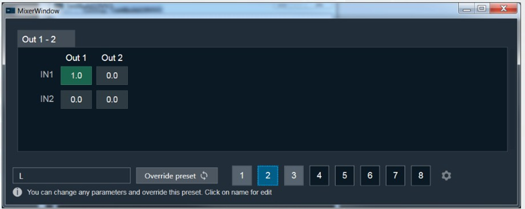
Example 3: “IN1” is muted and “IN2” is sent to channel two.
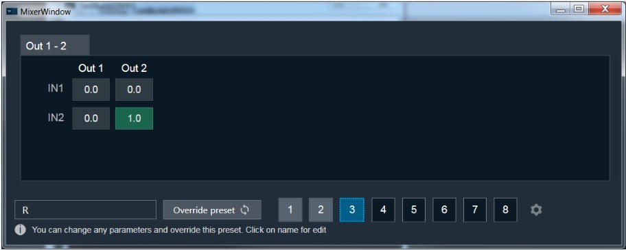
Set Linear Gain
When you click on a cell, you can change the gain value using the keyboard.
To set the value to zero or one, press CTRL and use the mouse scroll to adjust the value, or simply enter the values.
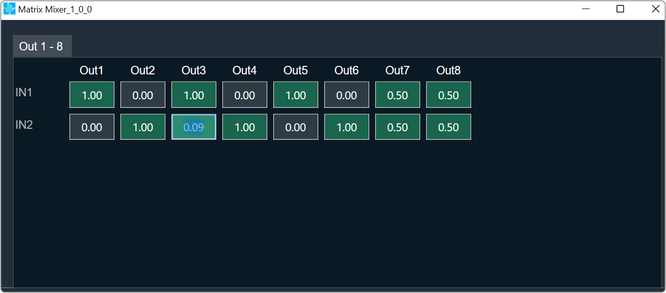
Cell Selection Methods
Single cell selection method: You can select a single cell with the mouse by using the left click or the tab key on the keyboard. The selected cell will be highlighted as you can see in the example below. The text inside the selected cell is editable.
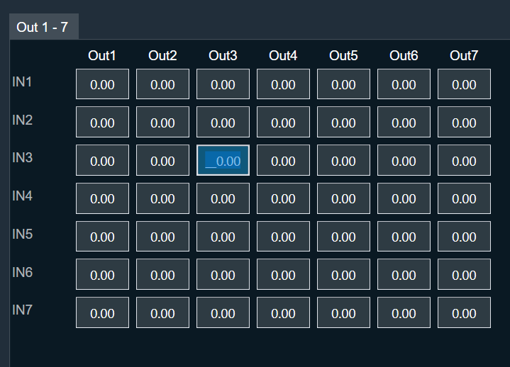
Multiple cell selection methods: There are two ways to select multiple cell.
- Method 1: By clicking and dragging with the mouse. This method is useful when you are selecting small range of cells.
- Method 2: By using keys on the keyboard. This method is useful when rendered outside of the view area when the grid scrolls either vertically or horizontally.
Method 1: To select multiple cells using mouse, follow the below steps.
- Place the cursor on cell.
- Select the cell by using the left mouse button and keep the mouse button pressed.
- Drag the cursor in the respective cell. Automatically the cells will selected in matrix form.
- Leave the mouse button.
The selected cell will be highlighted as you can see in the example below.

Method 2: To select multiple cells that is rendered outside of the view area when the grid scrolls either vertically or horizontally, you can use below method for selecting multiple cells.
If you want select a cell that is rendered outside of the view area when the grid scrolls either vertically or horizontally, you can use below method for selecting multiple cells.
- Click on a first cell of the range.
- Use scroll to navigate to last cell of the range.
- Hold Shift key and click on the last cell of the range. This will automatically select every cell in the matrix form.
The selected cell will be highlighted as you can see in the example below.

Selecting arbitrary cells is not allowed. Selection is always in the form of matrix.
A single tab displays the 12×12 matrix (INs and OUTs) in the matrix mixer. In the event that there are more AudioIn or AudioOut, it will be split up into multiple Tabs. The chosen region is reset and is not tracked when the tab is changed, as shown below.
Copy and Paste Functionality
You can copy and paste matrix mixer table data into Excel or vice versa. There are several methods for copying and pasting data.
Method 1: To copy panel cell data to Excel.
- Place the cursor on cell, select the cell by using the left mouse button and keep the mouse button pressed.
- Drag the cursor in the respective cell. Automatically the cells will selected in matrix form.
- Press Ctrl + C on your keyboard. The content gets copied to clipboard.
- Switch to Excel spreadsheet.
- Press Ctrl + V on your keyboard in the desired location within your Excel spreadsheet.
For seamless data exchange, the copied content uses a standard tab-delimited matrix format (‘\t’). This preserves the exact layout and allows easy import into various applications. This format is a standard across various applications.
Method 2: To copy data from Excel to matrix mixer table.
To paste content from Excel to Matrix Mixer first copy excel content to clipboard via keyboard Ctrl + C and on matrix mixer table select single cell from where content begin paste and use Ctrl + V to paste as shown below.
- In your Excel spreadsheet, use cursor on cell to select the respective cell from the Excel.
- Press Ctrl + C on your keyboard. This copies the data from the selected cells.
- Switch to Matrix Mixer table.
- Choose the cell and press Ctrl + V.

When you paste data, the affected cells will be highlighted. However, only the cell in the bottom right corner of the pasted region becomes active. This means you can only directly edit this cell with mouse or keyboard input.
Efficient pasting for repetitive data: For situations where you need to paste the same content in multiple locations, Matrix Mixer table offers a convenient repeat paste function.
- In your Excel spreadsheet, use cursor on cell to select the respective cell from the Excel.
- Press Ctrl + C on your keyboard. This copies the data from the selected cells.
- Switch to Matrix Mixer table.
- Choose the cell region larger than selection and press Ctrl + V once.
In this example, a 2×2 matrix is effectively replicated into a 4×4 area.

The copied matrix dimensions must be an exact multiple of the selected region for repeat pasting functionality. If this condition is not met, the content will be pasted only once starting from the active cell.
Efficient data copy within Matrix Mixer: Utilize keyboard shortcuts for quick and easy data movement. Select the cells you want to copy, press Ctrl + C to copy them. Next, choose the cell where you want to paste the copied data and press Ctrl + V. As shown below, this allows you to seamlessly copy information within the Matrix Mixer table.
Cross-panel data transfer: The copy and paste functionality in Matrix Mixer (Ctrl + C and Ctrl + V) offers flexibility beyond the panel. It enables you to efficiently move data between Matrix Mixer tabs and other applications that utilize a grid-based control, like the LUT Panel. This is achievable because copied content is stored on the clipboard, allowing access across the application and your operating system.
Copy and Paste Validation
Data exceeds paste area: When you try to paste content that’s larger than the selected region, you’ll see an “Out of Region” message. This means there’s not enough space to paste everything. You’ll have two options:
- Cancel: Choose this to avoid pasting any data and prevent accidental loss.
- OK: Click this to paste as much of the content as possible within the selected area. Some data might be cut off.
Tip: To ensure a complete paste, make sure the copied data is the same size or smaller than the area you’ve selected in Matrix Mixer.

Pasting incompatible data: If you try to paste content that contains non-numeric values (like text or symbols) into Matrix Mixer table, you’ll see an “Invalid Data” message. This means the data format isn’t compatible. You’ll have two options:
- Cancel: Choose this to avoid pasting any data and prevent errors.
- OK: Click this to paste only the valid numeric values from the copied content. Any invalid data will be ignored.
Tip: Make sure the copied data only contains numbers before pasting into Matrix Mixer.

Data values outside limits: When you try to paste content that contains values exceeding the allowed range for the selected cell(s), you’ll see an “Out of Range” message. Matrix Mixer has specific value limitations (e.g. 0-10). This means some of the data might be invalid. You’ll have two options:
- Cancel: Choose this to avoid pasting any data and prevent errors.
- OK: Click this to paste only the valid values within the allowed range for each cell. Any values outside the range will be ignored.
Tip: Before pasting, ensure the copied data adheres to the valid value range of the cells in your selected region.
Copying data with uneven columns: Matrix Mixer table allows you to paste data with variable columns, unlike Excel which requires a strict matrix format. This is helpful for situations where data from sources like Notepad might have missing values or uneven columns.
Example: As shown below, you can copy a 3×2 matrix from Notepad, where some columns might have empty cells. Matrix Mixer will interpret the data based on its structure and paste it accordingly.
Tip: While Matrix Mixer can handle variable dimensions, ensure the overall structure of the copied data remains consistent with the standard format i.e values separated by tab delimiter (‘\t’).

Preserving existing data: Matrix Mixer table allows you to selectively paste content while keeping your existing data intact. To achieve this, copy data from Excel with blank cells where you want to skip pasting. You might see an “Invalid Data” message because empty cells are considered invalid. However, clicking “OK” will continue the paste, leaving your existing values in those blank cells untouched.
Matrix Mixer table displays validation error messages only once, even if there are multiple invalid cells in the pasted data. Clicking “OK” will attempt to paste all valid data into the corresponding cells, while skipping any invalid values without affecting existing content.
6.3.Merger
The Merger audio object applies linear gain to all channels and sums all channel samples to generate an additional output channel. In the GTT, this object exposes m_NumAudioIn variables that represent the weights by which the input channels are scaled to generate the output for the last output channel. Scale values are to be set in db.
Use Case: This object can be deployed whenever a combination of input channels is required in the audio pipeline.
Merger Properties
Below table describes about the Merger audio object properties and functionality.

| Properties | Description |
| # of Audio In | Number of output channels is always one greater than the number of input channels. The first m_NumAudioIn output channels are just copies of the input channels.
Number of output channels is always number of input channels plus one. The first m_NumAudioIn output channels are just copies of the input channels. Default number of inputs pins is 2 and output pins is 3. |
| Display Name | Display the name of the Merger audio object in signal flow design. It can be changed based on the intended usage of the object. |
Mode
There are no mode available for Merger audio object.
Additional Parameters
There are no additional parameters available for Merger audio object.
Tuning Parameters
Below table describes the tuning parameters of Merger audio object.
| Parameter | Description | Data Type | Unit | Default | Range |
| Gain | Each input channel has one gain tuning parameter that specifies the weighting factor to be used to generate the additional output. . | float | dB | -128 | -128 to 20 |
Control Parameters
There are no control parameters available for Merger audio object.
Native Panel
Merger audio object does not support native panel.
6.4.Fader Matrix
The FaderMatrix audio object is used to calculate the weighted output based on a combination of input audio where the weighting factors are provided as control input.
Use Case: The FaderMatrix takes in a configurable number of input, output and control channels. Each output of this object is a weighted sum of all the input channels where weighting factors can be tuned from control inputs.
Fader Matrix Properties
Below table describes about the FaderMatrix audio object properties and functionality.
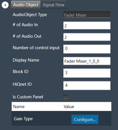
| Properties | Description |
| # of Audio In | Number of input channels.
|
| # of Audio Out | Number of output channels.
|
| # of Elements | Number of Control Inputs.
|
| Display Name | Display the name of the FaderMatrix audio object in signal flow design. It can be changed based on the intended usage of the object. |
Mode
There are no modes available for FaderMatrix audio object.
Additional Parameters
The FaderMatrix audio object can be configured with the following additional parameter:
| Parameters | Description | |
| Gain Type | The audio object has an additional configuration ‘Gain Type’ to specify the weighting factors scale.
|
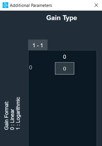 |
Tuning Parameters
The FaderMatrix audio object has one control index tuning parameter for each input channel that will used to compute the output of each channel. Thus there will be NumInputs * NumOutputs control indices (tuning parameters).
When the control index is set to zero, none of the control inputs will be used and this particular input will not be considered for computation of that particular output
| Parameter | Description | Range | Unit |
| Control Index | Index of the control input for selecting weight factor for each input and output combination. | 0 to NumElements | None |
Control Parameters
The FaderMatrix control is triggered whenever a control message is addressed to the audio object. The FaderMatrix audio object has configurable control input pins for weighting factors.
| Parameter | Description | Gain Type | Data Type | Range | Default | Unit |
| Weighting Factor | Weight factor for each input and output combination. | Linear | Float | -100 to 100 | 0 | None |
| Logarithmic | Float | -128 to 40 | -128 | dB |
Native Panel
The FaderMatrix AO does not support native panel.
7.Dynamic Object
Dynamic objects category contains following audio objects.
7.1.Compressor
The purpose of the Compressor audio object is to reduce the volume of loud sounds that exceed the certain threshold, while leaving quiet sounds unaffected. This is achieved by remapping the dynamic range of an audio signal to a smaller range. When the input signal rise above a predetermined threshold, the Compressor module weakens it, effectively lowering the dynamic range of the signal.
The Compressor audio object supports in-place computation based on the core type.
The Compressor audio object supports API resetObjectHistory, calling which would clear all the history data gathered over the audio and the internal states are restored to initial values.
The Compressor object supports two modes of operation. In Multi Set mode, the channels will be linked to configured sets. Each set will be tuned independently, and set attenuation will be applied uniformly to linked channels.
Use Case: Compressor audio object is perfect for usage as multichannel noisegate, limiter, and compressor to safeguard audio processing against unusual high amplitudes. Otherwise – the usage as audiophile stereo compressor in the signal path to achieve more audible density might not have the expected performance.
The compressor has two operating mode, namely One Set and Multi Set, and does not expose any variables to control.
Compressor Properties
Below table describes about the Compressor audio object properties and functionality.

| Properties | Description |
| # of Channels | Enter the number of channels. The number of audio channels it can process is configurable in the SFD and each channel has its own set of specifications.
|
| Max. delay [ms] | Specify the maximum possible delay for the audio object. It is applicable to all the audio channels. Maximum delay in msec (m_NumElements)
The number of channels and maximum delay are the configurable parameters in the SFD. |
| Display Name | Display name of the Compressor audio object in signal flow design. It can be changed based on the intended usage of the object. |
Mode
The Compressor audio object supports two modes of operation.
- One Set
- Multi Set


| Mode | Description |
|---|---|
| One Set | Tuning will be applied for all the channels. State variable: Attenuation will be updated at each instance (not per-channel basis) |
| Multi Set |
Channels will be linked to different sets in this mode. Additional parameter: Number of Sets can be configured for channel linking. Each set of linked channels can be tuned with set based tuning parameters such as Compressor Threshold, Release time, Attack time, etc. Common tuning parameters are applicable for all channels irrespective of their linked sets. State variable: Attenuation will be computed separately for each set. Channel <n> SetId parameter can be used to link the channel n with any of the available configured set. |
Additional Parameters
The Compressor audio object has one additional parameter, named Number of Sets.

| Properties | Description |
|---|---|
| Number of Sets | To configure the number of sets for grouping and linking the available channels. Configurable only when Object Mode: Multi Set is enabled.
|
Tuning Parameters
All Compressor audio object parameters are shared in One Set object mode. This means that there is only one set of parameters, common to all the input channels, that controls a single instance of the audio object.
In Multi Set object mode, the tuning parameters for each set can be used separately for the channels linked to it. The common tuning parameters are applicable for all the channels irrespective of their linked set.
Below table describes the tuning parameters of Compression audio object.
| Parameter | Description | Data Type | Unit | Default | Offset | Range |
| Compressor Threshold |
Level of the compressor activation. In Multi Set mode, it will be part of set tuning parameters. |
Float | db | -30 | 0 | -120 to 0 |
| Attack Time |
Time needed to compress signal to the target value. The signal level is reduced by 6 dB in this duration. In Multi Set mode, it will be part of set tuning parameters. |
Float | s | 0.02 | 4 | 0.001 to 0.5 |
| Release Time |
Time needed to restore original level of the signal after its return below threshold. The signal level is restored by 6 dB in this duration. In Multi Set mode, it will be part of set tuning parameters. |
Float | s | 0.05 | 8 | 0.001 to 0.5 |
| Compression ratio |
Amount of compression applied to signal when its level is above threshold. In Multi Set mode, it will be part of set tuning parameters. |
Float | None | 3 | 12 | 1 to 100 |
| RMS Smoothing (A) |
Coefficient of the RMS filter used for calculating RMS level of input signal. In Multi Set mode, it will be part of set tuning parameters. |
Float | None | 0.8 | 16 | 0 to 1 |
| Knee width/Soft Knee |
The half width of smooth transition band around threshold point. In Multi Set mode, it will be part of set tuning parameters. |
Float | dB | 3 | 20 | 0 to 120 |
| Make-up (after) gain |
Value of additional gain applied to the output signal. In Multi Set mode, it will be part of set tuning parameters. |
Float | dB | 0 | 24 | -128 to 20 |
| Noise gate threshold |
Level of the noise gate activation. In Multi Set mode, it will be part of set tuning parameters. |
Float | dB | -128 | 28 | -128 to 20 |
| Bypass | When this value is equal one the compressor is transparent.
In Multi Set mode, it will be part of set tuning parameters. |
ULong | None | 0 | 32 | 0 to 1 |
| Look ahead buffer size (Delay) |
Amount of time that the input signal is delayed to apply compression gain. In Multi Set mode, it will be part of common tuning parameters. |
Float | s | 0 | 36 | 0 to Max Delay |
| LP coefficient b0 |
Antialiasing filter’s b0 coefficient. In Multi Set mode, it will be part of common tuning parameters. |
Float | None | 1 | 40 | 0 to 1 |
| LP coefficient b1 |
Antialiasing filter’s b1 coefficient. In Multi Set mode, it will be part of common tuning parameters. |
Float | None | 0 | 44 | 0 to 1 |
| LP coefficient a1 |
Antialiasing filter’s a1 coefficient. In Multi Set mode, it will be part of common tuning parameters. |
Float | None | 0 | 48 | 0 to 1 |
| Noise gate bypass |
This is used to bypass noise gate functionality completely. When set to 1, the noise gating is disabled. In Multi Set mode, it will be part of common tuning parameters. |
ULong | None | 0 | 52 | 0 to 1 |
| Channel <n> SetId |
To link the channel <n> with the available configured sets in Multi Set object mode. This tuning parameter is available only in Multi Set mode. |
ULong | None | 0 | 56 | 0 to (Number of Sets -1) |
State Parameters
| Parameter | Description | Data Type | Unit | Default | Offset | Range |
| Attenuation | Indicates the amount of the computed attenuation when the compressor is active. For One Set object mode, the computed attenuation is applied on all channels. For Multi Set object mode, the computed attenuation at each set will be applied only to the channels linked to that particular set. | Float | dB | 0 | 60 | 0 to 128 |
Control Parameters
There are no control parameters available for Compressor audio object.
7.1.1.Compressor Panel
The Compressor panel is associated with Compressor audio object and can be used for tuning compression on an input signal. When you update parameters in either the SV Explorer or the native panel, the controls in the Compressor native panel should be in sync.
The Compressor panel works currently only for One Set Mode.
The Compressor panel has two tabs “Tuning” and “Advance Settings”. Tuning tab is the default tab.
Tuning Tab
You can configure following state variables via Tuning Tab.
- Compression Ratio
- Compressor Threshold
- Soft Knee
- Attack Time
- Release Time
- Noise Gate Threshold
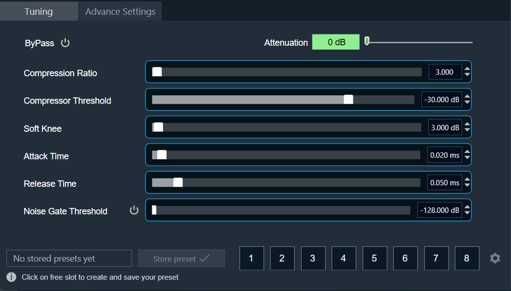
To disable the compressor, use the ByPass option. This will leave all controls in the Tuning and Advance Settings disabled and prevent any SV modifications.

The Attenuation option shown on the top right corner is read only value along with a scale indicator which shows level of attenuation and does not have any user interaction.
| Range | Color |
| 0 dB – 10 dB | |
| 10 dB – 20 dB |  |
| 20 dB – Max |  |
You can explicitly turn off Noise Gate Threshold by using Noise Gate Bypass option.

Advance Settings Tab
You can configure following state variables via Advance Settings.
- RMS Smoothing
- Make-up Gain
- Look Ahead Buffer Size
- Lp coefficient b0
- Lp coefficient b1
- Lp coefficient a1

Tuned parameters can be stored and recalled via Store Preset option available on the panel and is accessible in both the tabs.
Steps to store tuning parameters configuration.
- Configure the tuning parameters and select the free preset slot numbers, enter the name of the slot, and click Store preset. This saves and stores the current tuning data to the selected slot.
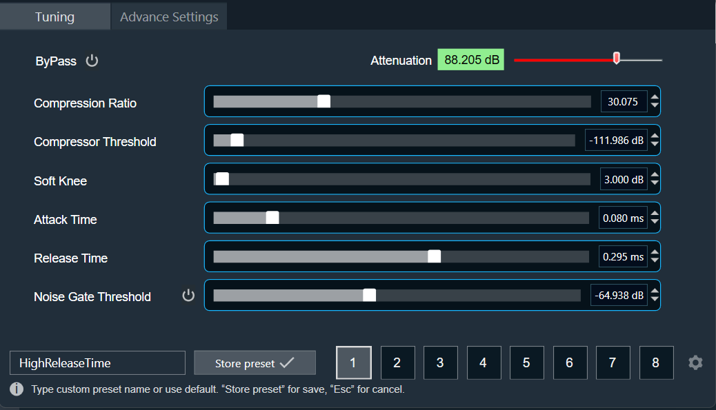
If you do not enter a name of the slot, then it will take the default named “New Preset”.
You can switch between presets slots and apply their values by simply clicking on them. Additionally, after clicking to override the preset, you can modify the tuning values in that tab or change the preset name.
To reset the selected preset or all the preset values.
- Click Reset Selected to clear the preset that is currently selected.
- Click Reset All to clear every preset in the corresponding native panel.
7.2.Limiter
The purpose of Limiter audio object is to control the output level of the audio.
This AO supports in-place computation based on the core type.
Use Case: The Limiter AO can be used wherever there is a necessity to limit the signal level to be below a safe threshold level. A typical example is to protect speakers from unsafe signal levels.
Limiter Properties
Below table describes about the Limiter audio object properties and functionality.

| Properties | Description |
| # of Channels | The number of audio channels it can process is configurable in the SFD and each channel has its own set of specifications.
|
| Display Name | Display name of the Limiter audio object in signal flow design. It can be changed based on the intended usage of the object. |
Mode
The Limiter audio object supports following three modes:
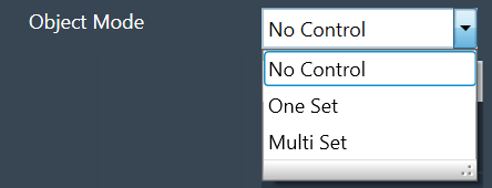
- No Control: No option for changing threshold value through control input. This is the default mode.
- One Set: One control input whose value is applied to change the threshold of all the channels
- Multi Set: Individual control input for each channel to change the threshold. If the number of channels exceeds 1, the control inputs are grouped as one block control input.
Additional Parameters
| Parameter | Description | |
| Max Lookahead |
Max Lookahead value is used to define the maximum lookahead time. During tuning from GTT, you can vary the lookahead time from 0 to the value set in the additional parameter. The memory requirement largely depends on the lookahead time, and this feature helps you to define their optimal maximum lookahead time based on the memory availability. This can be configured during design time.
Size of the lookahead delay buffer (in float words) = round (sampleRate * Max Lookahead) For a sample rate of 48000 and maximum lookahead of 0.15 s, the required buffer size is 7200 float Words. Hence this variable is made configurable to enable the user to choose optimal maximum lookahead value based on the available memory. |
 |
| Threshold Type |
This additional variable is used only in One Set and Multi Set modes. Under this modes, the AO will be having control input(s) and through this additional variable the user configures whether to use the control input value as absolute threshold or offset threshold. This option can be configured during design time.
The default value is 0. |
 |
Attack Phase
The Limiter operates in two modes during the attack phase when the input signal level is higher than the desired threshold.
- Fixed attenuation of 10 dB within the given attack time if the difference between the input signal level and the threshold is much higher. This phase is used initially to bring down the Limiter output quickly closer to the threshold.
- Adaptive attenuation if the threshold is slightly lower than the input signal level. This is deployed towards the end of attack phase for fine tuning the output level to match the threshold.
Hence if the threshold is less than the input signal by less than or equal to 10 dB, then within the given attack time the Limiter output is restricted to the threshold level ± 1 dB.
If the threshold is much lower than the input signal level (say 30 dB), the difference is first brought down to less than 20 dB within the attack time; the difference is further reduced to less than 10 dB within twice the attack time; finally the output matches the threshold ± 5% within thrice the attack time.
Release Phase
The release time is the time taken by the Limiter output to follow the input signal level from the time the input signal level drops below the threshold. During this phase, the Limiter output follows exponential (time constant) growth to reach the input level.
Accordingly the output level will be as given below during this phase (If the release time is denoted as R, and the difference between the output level at the start of release phase and the input signal level is P dB):
- After R sec : 63% of P dB
- After 2R sec : 86% of P dB
- After 3R sec : 95% of P dB
Tuning Parameters
The tuning parameters are limited to safe range such that Limiter audio object shall not produces NaNs.
In GTT, the limiter exposes the following parameters for each channel of the limiter:
| Parameters | Description | Type | Range | Default |
| Gain | Controls the upper bound of gain that the limiter applies on weak signals. | Float | 0 to 30 | 0 dB |
| Threshold | Controls where the limiter begins to activate. | Float | -30 to 0 | 0 dB |
| Attack Time | Controls the limiter’s attack time for each channel. | Float | 0.1 to 20 | 1 ms |
| Release Time | Controls the limiter’s release/hold time for each channel. | Float | 1 to 2000 | 150 ms |
| Hold Time | Controls the hold counter. | Float | 0 to 10 | 10 ms |
| Hold Threshold | Controls where the limiter enters hold or release. | Float | -1 to 0 | 0 dB |
| Look Ahead Time | Look Ahead buffer for controlling the overshoots. | Float | 0 to Max Lookahead | 0.0015 s |
| Bypass | Flag to bypass the Limiter operation for the particular channel. | Unsigned Long |
0 to 1 0 – Bypass Disable 1 – Bypass Enable |
0 |
State Parameters
| Parameters | Description | Type | Unit | Range | Default |
| Attenuation | The attenuation value for each channel indicates the amount of the gain reduction (attenuation) applied when the Limiter is active.
This value will not be updated while the limiter is in the ‘Bypass’ state. |
Float | dB | 0 to 60 | 0 dB |
| Effective Threshold |
Indicates the actual threshold value applied – for each channel. | Float | dB | -60 to 0 | 0 dB |
When the control input of the Limiter AO is configured as Absolute Threshold, the last applied setting will be used internally; which means the tuning parameter change will overwrite the control input and vice versa.
Control Parameters
The Control audio object does not have any control output in any modes. However, the AO has control input(s) in One Set and Multi Set modes.
- In One Set mode, the object has one control input whose value is applicable for all channels.
- In Multi Set mode, the number of control inputs is same as the number of channels – each channel having a dedicated control input. These control inputs in Multi Set mode are grouped as one Block Control input when the number of control inputs exceeds 1.
For further info on the Limiter audio object and it’s functional behaviour, please also refer to Limiter User Guide Supplement.
7.2.1.Limiter Panel
The Limiter Panel is used for changing the gain, threshold, hold threshold, attack time, hold time, and release time values for each channel.
The Limiter panel displays the current attenuation value for information purpose only. Attenuation is a state-type parameter. This means the attenuation value is coming from the device and cannot be modified within the Limiter panel. To get the current attenuation value, you need to stream the attenuation state variable.
 There is a tooltip for Attack Time that describes its behavior as shown below.

Similarly, tooltip is available for Release Time for its behavior as show below.

Changing Value
You can change the gain value in four ways:
- Using slider button: Select the slider to adjust the value.
- Using mouse scroll: Click on the respective column and use mouse scroll to adjust the value.
- Using text box: Select the respective column and enter the dB value within the specified minimum and maximum range. Once you’ve entered the value, press Enter, and the slider will automatically adjust based on the input.
- Using the increment and decrement buttons
 you can change the gain value.
Maximum / Minimum Gain Value
Maximum and minimum gain values are from corresponding state variable of Limiter.
Threshold Values
Maximum and minimum threshold values are derived from the GTT in the parameter store.
When either of the threshold values is reached, the Gain value bar will turn into red.
- Maximum threshold value: 95 %
- Minimum threshold value: Not set
For further info on the Limiter audio object and its functional behavior, please also refer to the Limiter User Guide Supplement.
7.3.Bass Enhancer
The Bass Enhancer audio object allows to enhance the signal level of the low frequency components for better listening experience. The is achieved by generating harmonics for the low frequency components of interest and attenuates the higher harmonics after retaining the second harmonic alone. This is to avoid interference with the higher frequency components of the original signal.
The Bass Enhancement audio object is popular in the consumer electronics industry where good bass quality is expected from small or flat speakers. Bass performance is lacking in these speakers due to physical limitations and cost constraints. Bass Enhancement solutions are based on the psychoacoustic phenomenon where the human auditory system can perceive fundamental frequency from its higher harmonics. This is done with non-linear operations to generate harmonics that enhance bass virtually.
The audio object splits the signal into low pass and high pass based on the tunable set cut-off frequency. The harmonics are generated for the low-pass signal.
Input & Output:
The input gain scaling is applied on both the channels. The algorithm then separates the high pass signal based on the cutoff frequency set for both the left and right channels. Also, the left and right channels are merged, and the resultant mono signal is applied to the low pass filter.
The process of generating harmonics and attenuating higher harmonics are done only with the mono signal. This is done to reduce computing complexity. Bass Enhancer uses the same coefficient set for both left and right input channels. So, the output high pass filtered left and right channels will have same outputs if the input left and right channels are same.
Bass Enhancer have 3 audio outputs: High pass filtered Left, High pass filtered right, and Low pass filtered with harmonics shaping enhanced mono. The number of input channels is 2 and the number of output channels is 3.
The input channel order is:
- [1] Left
- [2] Right
The output channel order is:
- [1] Left (High pass filtered)
- [2] Right (High pass filtered)
- [3] Enhanced Mono (Low Pass with harmonics shaping)
Use case: This object can be deployed wherever a Bass Enhancing effect is required in the audio pipeline.
Bass Enhancer Properties
Below table describes about the Bass Enhancer audio object properties and functionality.

| Properties | Description |
| Display Name | Display name of the Bass Enhancer audio object in signal flow design. It can be changed based on the intended usage of the object. |
Mode
There are no mode available for Bass Enhancer audio object.
Additional Parameters
The Bass Enhancer audio object doesn’t have any additional parameters.
Tuning Parameters
| Parameter | Description | Data Type | Default | Unit | Step Size | Range |
| Bypass | BassEnhancer AO bypass On /Off | int | 0 | None | None |
0 – Bypass Off 1 – Bypass On |
| InputGain | Gain to be applied on the Input signal (in DB) | Float | 0.0 | dB | 0.01 | -30.0 to 6.0 |
| FcLplnp | Cut-off frequency for Low pass and High pass filters | Float | 250 | Hz | 0.01 | 10.0 to 1000.0 |
| DistOdd | Distortion Factor Odd | Float | 0.1 | – | 0.01 | 0.0 to 0.5 |
| DistEven | Distortion Factor Even | Float | 0.1 | – | 0.01 | 0.0 to 0.5 |
Control Parameters
| Parameter | Description | Range | Default |
| BassEnhancerEnable | BassEnhancer AO On/Off |
0 – Disable 1 – Enable |
1 |
7.3.1.Bass Enhancer Panel
Audio engineers use Bass Enhancer audio object when they require bass enhancing effect in their audio pipeline. To adjust the parameters of the Bass Enhancer audio object, a custom native panel is provided. This panel allows for fine-tuning and customization of the Bass Enhancer settings.
User interface for every Bass Enhancer is the same and looks like the below figure.
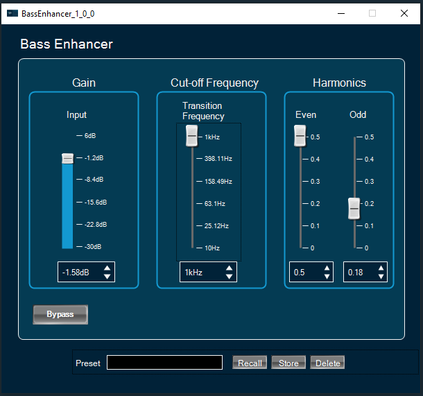
- Activate bypass feature by clicking on “Bypass” button. If active the button has a red background.
- Apply gain to input or bass signals using vertical faders or spinners under the “Gain” widget.
- Change transition frequency and octave factor using vertical faders or spinners under the “Cut-off Frequency” widget.
- Change even and odd distortion factors using vertical faders or spinners under the “harmonics” widget.
7.4.NonlinearClip
The NonlinearClip audio object is used to add a clip-on continuous input signal every time the signal level exceeds the clip threshold value. If Input signal value is exceeded clip threshold the output value is set to Clip threshold value.
Features of NonlinearClip audio object.
- NonlinearClip AO is supported for all framework configurable sample rates and block lengths.
- NonlinearClip AO is supported for both Win64 and GUL platforms.
Use Cases: This object can be deployed whenever a Nonlinear Clip is required in the audio pipeline.
NonlinearClip Properties
Below table describes about the NonlinearClip audio object properties and functionality.

| Properties | Description |
| # of Audio In | Enter the number of audio input. The number of audio outputs is the same than the audio inputs.
|
| Display Name | Display name of the NonlinearClip audio object in signal flow design. It can be changed based on the intended usage of the object. |
Mode
The NonlinearClip audio object doesn’t have any mode.
Additional Parameters
The NonlinearClip audio object doesn’t have any additional parameters.
Tuning Parameters
| Parameter | Description | Default | Range | Units |
| ClipThreshold | Clip threshold value to where clip is applied. | 0.0 | -120 to 6.0 | dB |
Control Parameters
The NonlinearClip audio object don’t support control parameters.
Native Panel
NonlinearClip audio object does not support native panel.
7.5.AudioLevelizer
The purpose of the AudioLevelizer audio object is to automatically adjust and balance the loudness of incoming audio signals, regardless of the input from different audio sources. Basically, this audio object allows you to continuously maintains the perceived loudness of audio sources without performing volume adjustments when switching between audio sources.
It induces a fixed latency of 512 samples (~10 ms at 48 kHz sample rate) between the audio input and the output.
Example: Tuner > USB. The AudioLevelizer will adjust the volume automatically to make sure the perceived loudness will be equal after the source switch.
AudioLevelizer Properties
Below table describes about the AudioLevelizer audio object properties and functionality.

| Properties | Description |
| Display Name | Display name of the AudioLevelizer audio object in signal flow design. It can be changed based on the intended usage of the object. |
Mode
The Audiolevelizer audio object doesn’t have any mode.
Additional Parameters
The Audiolevelizer audio object doesn’t have any additional parameters.
Tuning Parameters
| Parameter | Description | Type | Offset | unit | Range | Default |
| Intensity | Sets the balance between dry gain and wet gain.
0% = dry gain only; 100% = wet gain only. |
Float | 0 | % | 0 to 100 | 60 |
| TargetLoudness | equivalent sound level | Float | 4 | dB | -65 to 12 | 7 |
| AttackRate0 | short term attack rate for overall gain adjustment | Float | 8 | ms | 6 to 250 | 32 |
| AttackRateGrowTime | amount of time from short term to the long-term attack rate for overall gain adjustment | Float | 12 | s | 0 to 30 | 1 |
| AttackRateMax | long term (i.e. final) attack rate for overall gain adjustment | Float | 16 | ms | 0 to 250 | 85 |
| ReleaseRate0 | Short term (i.e. start) release rate for overall gain adjustment. | Float | 20 | ms | 6 to 12000 | 130 |
| ReleaseRateGrowTime | Amount of time from the short term to the long-term release rate for overall gain adjustment. | Float | 24 | s | 0 to 30 | 3 |
| ReleaseRateMax | Long term (i.e. final) release rate for overall gain adjustment. | Float | 28 | ms | 0 to 30000 | 5000 |
| RampRangeMin | maximum allowable attenuation to reach the target loudness | Float | 32 | dB | -24 to 24 | 5 |
| RampRangeMax | maximum allowable boost to reach the target loudness | Float | 36 | dB | -24 to 24 | 11 |
| PauseTime | minimum continuous time the signal must be below the PauseThreshold | Float | 40 | s | 0.001 to 3 | 0.25 |
| SignalTime | minimum continuous time the signal must be above the SignalThreshold | Float | 44 | ms | 20 to 50 | 26 |
| PauseThreshold | threshold for the signal | Float | 48 | dB | -99 to -2 | -76 |
| SignalThreshold | threshold for the input | Float | 52 | dB | -99 to – 1 | -75 |
| ClipGuardThreshold | threshold for the maximum allowed peak value | Float | 56 | dB | -12 to -12 | 0 |
| CompressorThreshold | threshold below which the surround channel compressor is activated | Float | 60 | dB | -60 to -1 | -6 |
| CompressorRatio | desired ratio of the input to the output gain for the surround channels. | Float | 64 | dB | 0 to 100 | 25 |
| SpeechAdjustDepthCenter | maximum amount of allowable boost for center channel when speech is detected | Float | 68 | dB | 0 to 12 | 6 |
| SpeechAdjustDepthFrontSurr | maximum amount of allowable attenuation for the surround and front channels when speech is detected in the center channel. | Float | 72 | dB | -12 to 0 | 0 |
| SpeechAdjustAttackTime | attack time for center boost / front attenuation | Float | 76 | ms | 6 to 30000 | 1000 |
| SpeechAdjustReleaseTime | release time for center boost / front attenuation | Float | 80 | ms | 6 to 30000 | 10000 |
| SpeechAdjustThreshold | center level threshold for center boost / front attenuation | Float | 84 | dB | -24 to 0 | -6 |
Control Parameters
The Audiolevelizer audio object don’t support control parameters.
7.5.1.AudioLevelizer Panel
The Audiolevelizer audio object supports native panel. The native panel window consists of slider bars and rotary for different tuning parameters viz. compressor threshold, compressor ratio, Attack time, Release Time, Ramp Range etc.
To open the native panel, double-click on the audiolevelizer object in the SFD.

7.6.Nonlinear Polynomial
The Nonlinear Polynomial audio object provides output based on the quadratic equation.
Features of NonlinearPolynomial.
- NonlinearPolynomial audio object is supported for all framework configurable sample rates.
- NonlinearPolynomial audio object is supported for all framework configurable block lengths greater than 4 and multiple of 4 up to 4096.
- NonlinearPolynomial audio object is supported for both Win64 and GUL platforms.
The audio object supports in-place computation based on the core type.
Nonlinear Polynomial Properties
Below table describes about the Nonlinear Polynomial audio object properties and functionality.

| Properties | Description |
| # of Audio In | Enter the number of audio input.
The number of audio outputs is the same than the audio inputs. |
| Display Name | Display name of the Nonlinear Polynomial audio object in signal flow design. It can be changed based on the intended usage of the object. |
Mode
There are no mode available for Nonlinear Polynomial audio object.
Additional Parameters
The Nonlinear Polynomial audio object doesn’t have any additional parameters.
Tuning Parameters
Nonlinear Polynomial has two modes.
- 0: Polynomial mode
- 1: Squared mode
Default is Polynomial mode.
| Parameter | Description | Data Type | Default | Range | Units |
| A coefficient | The scaling factor for squared input sample | Float | 0.0 | -256.0 to 256.0 | None |
| B coefficient | The scaling factor for input sample | Float | 1.0 | -256.0 to 256.0 | None |
| C coefficient | The offset to the sample | Float | 0.0 | -256.0 to 256.0 | None |
Control Parameters
The Nonlinear Polynomial audio object doesn’t have any control parameters.
Native Panel
The Nonlinear Polynomial audio object don’t have any native panel.
7.7.dbxLimiter
The dbx limiter audio object controls the input signal if signal level crosses threshold level. It operates as a RMS Limiter and Peak Limiter.
The below figure displays the panel for dbx Limiter from audio architect (Professional audio tuning and design tool).

The dbx limiter has an optional processing called Peakstop plus processor which further compresses the output signal from RMS limiter. It operates as an RMS limiter during normal operation and when you enable Peakstop plus parameter it acts as a peak limiter.
Use Case: This object can be deployed whenever an audio limiter needs to be introduced in an audio pipeline.
The Dbxlimiter algorithm performs the following operations on the input signal to achieve the signal limiting.
- RMS detection is performed on all channels (each channel has its own RMS detector).
- Any linked channels update their RMS info with the max of the linked channels’ RMS values.
- Compression logic is applied to the RMS values to modify them if in or above the knee.
- Attack/Hold/Release logic is applied to compute the final gain reduction amount (dB).
- The dB gains are converted to linear gains and applied to the audio signal.
- If active for this channel, PeakStop+ sample-wise limiting is applied to the audio signal.
dbxLimiter Properties
Below table describes about the dbx limiter audio object properties and functionality.

| Properties | Description |
| # of Channels | Enter the number of channels. The number of audio channels it can process is configurable in SFD and each channel has its own set of specifications.
The number of audio outputs is the same than the audio inputs. |
| Display Name | Display name of the dbxLimiter audio object in signal flow design. It can be changed based on the intended usage of the object. |
Mode
The dbxLimiter audio object doesn’t support any mode.
Additional Parameters
The dbxLimiter audio object doesn’t have any additional parameters.
Tuning Parameters
| Name | Description | Offset | Type | Unit | Default | Range |
| Threshold | Level of the dbx limiter activation. | 0 | float | dB | 0 | -60.0 to 0.0 |
| Attack time | Time needed to limit signal to the target value. | 4 | float | ms | 10 | 0.1 to 200 |
| Hold Time | Time for which the signal is “held” at threshold even though the input has fallen below threshold. | 8 | float | ms | 0 | 0.0 to 500 |
| Release | The rate at which the release process happens. Release is when the limiter stops compressing/limiting the signal. | 12 | float | dB/s* | 5 | 5.0 to 360.0 |
| Overeasy | The half width of smooth transition band around threshold point. | 16 | float | dB** | 0 | 0 to 100 |
| Peakstop Plus | When this flag is set, Peakstop+ processor gets enabled. | 20 | ULong | NULL | 0 | 0 to 1 |
| Overshoot | In Peak Mode, the output signal will not exceed the level set by overshoot. | 24 | float | dB | 2 | 2 to12 |
| Bypass | When this value is equal one the dbx limiter is transparent. | 28 | ULong | NULL | 0 | 0 to 1 |
| Automode Enable | When this value is equal to one, the dbx limiter algorithm sets the Attack, Hold, and Release parameters in real time based on the incoming signal | 32 | ULong | NULL | 0 | 0 to 1 |
| ChannelLinkId | This parameter indicates the channel that is linked to the current channel. The maximum RMS values of the current and the linked would be considered for the limiting | 36 | ULong | NULL | Channel number | 0 to 255 |
- *Due to the limitation in GTT the unit is kept as ms even though it is actually dB/s.
- **The range used in Audio Architect, the tool used by PRO audio uses a range of only 0 – 10 dB. However, this does not result in any noticeable quality difference to the audio. So, the range of Overeasy has been increased here to a wider range. This can however be changed later based on the requirements of the product teams.
Control Parameters
The dbxLimiter audio object doesn’t have any control parameters.
State Parameters
| Parameter Name | Data Type | Default Value | Range | Description |
| Threshold meter | Float | 0 | 0 to 2 | Indicates the level of the signal after compression |
Native Panel
The dbxLimiter audio object does not support native panel.
7.8.Ducker
The aim of Ducker is to attenuate the level of one audio signal in the presence of another signal. The ducker algorithm is primarily used for reducing the level of the background music track during announcement. This audio object works in tandem with a level detector block or a different control input. A very simple reference implementation of a peak level detector is included EconomyLevel.
Ducker Properties
Below table describes about the Ducker audio object properties and functionality.

| Properties | Descriptions |
| # of channels | The number of input channels are configurable.
The number of output channels are equal to the number of input channels. |
| Display Name | Display name of the Ducker audio object in signal flow design. It can be changed based on the intended usage of the object. |
Mode
There are no mode available for Ducker audio object.
Additional Parameters
| Parameter | Descriptions | |
| Side Chain Level Scale |
Side Chain Level Scale is in linear or dB scale, which can be selected during design time. 0 – Linear scale 1 – dB scale |
 |
| Ducker Operation Mode |
The Ducker audio object operates in two modes and the mode can be selected using an additional configuration “Ducker Operation Mode”. Ducker AO operation mode
Standard mode is the default.
|
 |
Tuning Parameters
| Parameter | Data Type | Unit | Default Value | Range | Description |
| Threshold | Float | dB | -30 dB | -128 to 0 | minimal value of the incoming level parameter to trigger ducking |
| Attenuation | Float | dB | 20 dB | 0 to 128 | How much the signal will be attenuated when ducking is active |
| Attack time | Float | s | 1 s | 0.01 to 3 | The time it’ll take for the signal to transition from the full level (0dB) to the ducking level. |
| Release time | Float | s | 1 s | 0.01 to 10 | The time it’ll take for the signal to transition from the ducking level back to the full level (0dB) after the ducking condition expires |
| Hold time | Float | s | 1 s | 0.01 to 3 | The minimum amount of time from the start of the ducking or from the detection of incoming level above threshold (whichever is greater) for the ducking to start releasing |
| Bypass | ULong | 0 | 0 and 1 | Whether the processing should be bypassed.
|
Control Parameters
| Parameters | Descriptions | Range |
|
Control input in linear scale Or Control input in dB scale |
Control input (Side Chain Level) data in linear scale. The range is from 0.0 to 1.0 in normalized. Control input (Side Chain Level) data in dB scale. The range is from -128.0 to 0.0 |
0.0 to 1.0 -128.0 to 0.0 |
| Threshold |
The minimal value of incoming control signal to trigger ducking. It is available only in enhanced mode. |
-128 to 0 dB |
| Attenuation |
The amount of the signal that will be attenuated when ducking is active. It is available only in enhanced mode. |
0 to 128 dB |
| Bypass |
Whether the processing should be bypassed. 0 – Bypass disabled (Default) 1 – Bypass enabled It is available only in enhanced mode. |
0 and 1 |
State Parameters
Ducker exposes the following state parameters to indicate the status of the audio object, and these are streamable.
| Parameter | Data Type | Default Value | Unit | Range | Description |
| Side Chain Level | Float | 0 dB | dB | -128 to 0 dB | The control input amplitude value in dB. |
| Ducking status | Float | 0 | 0 to 1 | The ducking process is applied or not. | |
| Gain attenuation | Float | 0 dB | dB | 0 to 128 dB | The amplitude difference between input and output audio in dB. |
Native Panel
The Ducker audio object don’t have any native panel.
7.9.EconomyLevel
The aim of Economy level audio object is to detect the absolute peak level in the input signal. The audio object algorithm is primarily used for reducing the level of the background music track during announcement. The EconomyLevel block is a control source generator for the Ducker object. It should be inserted separately into the signal path that is supposed to control the Ducker object and connected to the main Ducker object via control routing.
The word ‘Economy’ in the block names reflects the original names used within Studer OnAir Micro console firmware. These blocks are optimized for performance and are suitable for using with mixer consoles and performance-constrained embedded devices.
Economy level Control output depends on block length selected and input audio frequency.
Since economy level works on the data from one block of data presented to it, for lower block length and lower frequencies control output may not be static.
The basic features for the Economy level Object are:
- Integration with the xAF.
- Accessibility from the Signal Flow Designer Software. This allows the user to add the object within an audio pipeline.
- Fixed number of channels from within SFD. The number of input channels are always equal to the number of output channels
- The object has one control output channel
- Implementation on generic code.
- In-place computation support.
EconomyLevel Properties
Below table describes about the Economy level audio object properties and functionality.

| Properties | Descriptions |
| # of Channels | The number of input channels are configurable.
The number of output channels are equal to the number of input channels. |
Mode
There are no mode available for Economy level audio object.
Additional Parameters
| Parameter | Descriptions | |
| Control Output Data Scale |
The control output can be either in linear scale or dB scale which can be selected during design time using the Control Output Data Scale additional configuration. This audio object is targeted at Professional Audio usage, specifically. Control output data is in linear or dB scale. 0 – Linear scale 1 – dB scale |
 |
Tuning Parameters
There are no tuning parameters available for Economy level audio object.
Control Parameters
| Parameters | Descriptions |
| Control output in linear scale | Control output data in linear scale. The range is from 0.0 to 1.0 in normalized. |
| Control output in dB scale | Control output data in dB scale. The range is from -128.0 to 0.0 |
Native Panel
Economy level audio object does not support native panel.
7.10.AudioLevelizer 2
The purpose of AudioLevelizer 2 audio object is to automatically maintain perceived loudness of output, regardless of variations in input loudness from different audio sources. This eliminates the need to perform volume adjustments while switching between input audio sources. For example, while switching from Tuner to USB, the AudioLevelizer 2 will adjust the volume automatically to ensure the perceived loudness is maintained after the source switch.
AudioLevelizer 2 audio objects provides zone configuration to process incoming audio channels. The zones can be configured as single zone or multiple zones.In single zone configuration audio inputs can be mono , stereo or 5.1 channel.In multizone configuration audio inputs can be 2 to 12 stero channels or 11 stereo channels Plus one 5.1 channel.
AudioLevelizer 2 introduces latency based on frame size.
AudioLevelizer 2 Properties
Below table describes the AudioLevelizer 2 audio object properties and functionality.
Audio object properties in single zone mode
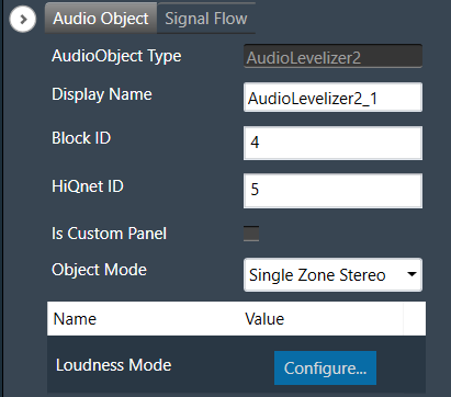
Audio object properties in multi zone mode

| Properties | Description |
| Display Name | Display the name of the AudioLevelizer 2 audio object in signal flow design. It can be changed based on the intended usage of the object. |
| Object Mode | AudioLevelizer 2 supports following modes
|
Mode
There are total 5 modes
| Name | Description |
| Single Zone Stereo | Supports single stereo input channels. |
| Single Zone Mono | Supports mono input channel. |
| Single Zone 5.1 channels | Supports 5.1 input channels. |
| Multizone Stereo | Supports multiple stereo input channels. Number of stereo inputs is configured from “Numer of zones”. |
| Multizone 5.1+Stereo | Supports 5.1 channel channels plus stereo input channels. Number of stereo input channels supported is configured from “Numer of zones” |
Additional parameters
| Parameter | Description | Unit | Range | Default |
| Loudness Mode |
To select loudness estimation method. Loudness estimation method can be either “ITU Loudness mode” or “Harman optimized”
|
None | 0 – 1 | 0 (Harman optimized) |
Tuning Parameters
AudioLevelizer 2 has below tuning parameter
| Parameter | Description | Data Type | Unit | Default | Offset | Range |
| Target Level | Long-term averaged Loudness Level at which each output signal is targeted to. | Float | LUFS(dB) | -17 | 0 | -35 to -5 |
| Relative Max LU | Output signals are capped to the loudness level set by the Relative Max LU relative to target level. | Float | LU(dB) | 15 | 4 | 0 to 30 |
State Parameters
| Parameter | Description | Data Type | Unit | Default | Offset | Range |
| Status |
Enable/Disable the ALZ core class for the corresponding Zone. 0: Mute zone 1: Zone Active For debug purpose this can be tuned. |
Float | None | 1 | 0 | [0, 1] |
| Applied Gain | To check the applied gain value of the corresponding zone. | Float | dB | NA | 4 | -50 to 50 |
| Noise Floor Triger | To check the silence/pause status of corresponding zone 0: Silence not detected. -10: Silence detected. | Float | 0 | 0 | 8 | [0 -10] |
8.Filter Objects
Filter objects category contains following audio objects.
8.1.ParameterBiquad
This ParameterBiquad audio object computes bi-quadratic filter coefficients and calculates the output of the input audio buffers processed through the filters that users specify.
Use Case: This audio object can be deployed whenever a user wants to filter a signal based on user specified parameters.
Parameter Biquad Properties
Below table describes about object properties and functionality of ParameterBiquad audio object.

| Properties | Descriptions |
| # of Channels | The object has a configurable number of channels. The number of audio inputs is always equal to the number of audio outputs. These channels are referred as subblocks. Filter has as many subblocks as number of channels and one additional subblock for Ramp characteristics.
|
| Number of biquads | The number of elements generally describes the number of filters requested by the user.
|
| Display Name | Display the name of the ParameterBiquad audio object in signal flow design. It can be changed based on the intended usage of the object. |
| Object Mode | ParameterBiquad audio object operates in one of the three modes.
|
Mode
The ParameterBiquad audio object operates in one of three modes and ramping is applicable in all modes:
| Mode | Description |
|---|---|
|
Parameter (Default) |
In this mode, the block receives the following filter specifications from the user for each filter in a channel. This mode generates a set of filters per channel, so each channel has its own set of unique filters.
In this mode, each channel can have its own set of coefficients and filter specifications. |
| Parameter One |
In this mode, the block receives the following filter specifications from the user for each filter in a channel: This mode generates a set of filter coefficients for all audio channels. The only difference between this mode and the Parameter mode is that this mode generates one set of coefficients for all channels as opposed to one set per channel.
In this mode, all channels use same set of filter/filter coefficients. This block uses the above filter specifications to calculate the filter coefficients based on the type of the filter requested by the user. The difference between Parameter mode and Parameter One mode is that Parameter One mode will apply the same set of filter coefficients to each channel whereas Parameter mode will apply different sets for different channels. This is identical to the Parameter Mode, except, instead of presenting the variables for each filter per channel, this mode only presents a set of coefficients per filter, regardless of the number of channels. |
| Parameter One Control Set |
This mode also allows to control the cut off frequency via a control input pin. This mode only uses one filter and applies the filter characteristics to all channels similar to Parameter One mode. It also exposes one control (accessible from the HU) variable to manipulate the cut-off frequency. This is identical to Parameter One Mode but it has only one filter. In addition to the above parameters, ParameterBiquad also exposes Ramp time configuration (both in state and tuning memory). For each channel in parameter mode and in Parameter One & Parameter One Mode Set Control Frequency single Ramp Time is exposed irrespective of number of channels. |
Additional Parameters
| Parameter | Description | |
| Biquad Topology | Allows the user to choose the filter topology at design time.
By default, it is configured for DFII. |
 |
| Tune Ramping On/Off |
Allows user to enable or disable the ramping during tuning. By default, ramping is disabled. 1 – Ramping Enable 0 – Ramping Disable Irrespective of this option, ramping characteristics are always available as tuning parameters that will be used whenever changes are made through control inputs. |
 |
Tuning Parameters
This table assumes subblocks are utilized. If a user were to tune without subblocks, they would need to account for the memory offsets for subblocks.
f = Filter # (starting from beginning of subblock)
| Parameter | Description | Data Type | Unit | Default | Memory Offset | Range |
|---|---|---|---|---|---|---|
| Frequency | Cut off frequency of the filter | float | Hz | 20 | f * 5 * 4 + 0 | 10 to 20000 |
| Gain | Gain | float | dB | 0 | f * 5 * 4 + 4 | -30 to 50 |
| Quality | Q factor of the filter | float | – | 0.7 | f * 5 * 4 + 8 | 0.1 to 116 |
| Type | Type of filter: lowpass/high pass/ shelve, etc | Int | – | 0 | f * 5 * 4 + 12 |
0 – BYPASS 15 – RESON |
| Bypass* | Bypass on or off (0 is on) | Int | – | 0 | f * 5 * 4 + 16 | 0 to 1 |
*ATTENTION: The Bypass logic is inverted. When Bypass value is set to 1, the AO applies filtering and generates the filtered output. When Bypass value is set to 0, the AO passes the input to the output. This need to be retained this way to maintain backward compatibility.
Last subblock irrespective of channels will be the ramp characteristics. Below is the memory layout for the last subblock. If m_NumChannels N,
- In Parameter mode last subblock will be N.
-
- For example, for 2 channels, subblock 0 and 1 are for the filters and subblock 2 is for ramp characteristics. When channels are changed to 3 channels, subblock 0, 1 and 2 are for the filters and subblock 3 is ramp characterics.
- Please note that subblock 2 (which was used for ramp characteristics when number of channels were 2) used for filter when number of channels are 3.
- Because of this, application using this AO, may not be able to retain the ramp characters when number of channels are changed.
- For example, for 2 channels, subblock 0 and 1 are for the filters and subblock 2 is for ramp characteristics. When channels are changed to 3 channels, subblock 0, 1 and 2 are for the filters and subblock 3 is ramp characterics.
- In Parameter One mode and Parameter One control set mode last subblock will be 2 irrespective of number of channels
Ramp Characteristics Subblock
| Last sub-block | Name | Type | Unit | Min | Max | Default Value | Offset | Description |
| Ch = 0 | Ramp time ch0 | float | ms | 0 | 500 | 0 | ch *4 | Ramp time for first channel |
| Ch = 1 | Ramp time ch1 | float | ms | 0 | 500 | 0 | ch * 4 | Ramp time for second channel |
| Ch = N – 1 | Ramp time ch(N-1) | float | ms | 0 | 500 | 0 | ch * 4 | Ramp time for last channel |
Control Parameters
There are no control parameters available for Parameter Biquad audio object.
8.1.1.Parameter Biquad Panel
The ParameterBiquad panel can be used to apply Biquad filters to the signal. It is accessed through the Normal biquad object and Parameter biquad audio object, each offers different modes. When using parameter one or parameter one control set mode, channel selection is not required since the identical biquad parameters are applied to all channels within the device.

Channel List
On the top left of the EqPanel, there is a list from which you can choose a channel for the current core. The current channel is marked with a green square and its details are displayed in the header of the channel list.

EQ Chart
This chart represents the influence of all Biquads on the frequency and phase response. The left axis shows the amplitude in dB, and the right axis shows the phase in degrees. The number of Biquads are defined with the Signal Flow Designer. The Biquads get dynamically managed inside the GTT. Most of the Biquads are represented by appropriate markers.

Markers
Markers are movable. Moving them allows you to amend the current Biquad parameters. Each marker corresponds to one or two Biquad parameters. For example, the equalizer shown below has three markers.

Biquad Settings
On the Biquad settings window, you can perform the following operations.

Enabling Bypass
- Click on the
 Bypass button to enable or disable Bypass.
 - In bypassed state, the button is red colored and green colored when biquad is in non-bypassed state.
Biquad is in bypassed state by default.
Change the Frequency, Gain, and Quality
- Frequency: It is used to set the center frequency of each filter.
- Gain: It is used to set the center frequency gain of each band of the filter. Not all filter types offer a variable gain.
- Quality: It is used to set the width of each band pass or notch type band of the filter. Not all filter types offer a variable quality factor.
-
- Using the increment and decrement buttons
 you can change the value.
Or - Select the tuner and use mouse scroll to adjust the value
- Using the increment and decrement buttons
Change Biquad type
The Biquad Filter Menu shows a list of all Biquads types that are set up in the amplifier for the current channel. You can change the Biquad type or remove the Biquad by setting it to Bypass (at the top of the list).

Biquad Chart Type

- Amplitude phase: It is used to turn on and off appropriate charts.
- Phase Unwrapped: It displays absolute values.
-
- If the phase is wrapped, the display is limited to ± 180 °.
- If the phase exceeds 180 ° or -180 ° it is continued on the other side of the vertical scale.
- Used Biquads: This informs you about the available Biquads. The first number is the number of Biquads that have not been bypassed. The second number is the number of available Biquads.
- Sample rate: It shows the sample rate at which the filters are operated.
Biquad Curve Legend
Click on Curve Legend to display all the associated legends. By default, all the curve legends are enabled on the graph. Uncheck the curve to hide it from the graph.

High Order Filters
The biquad object does not support natively high order filters. To work with high order filters, biquad panel can merge two low order filters into one high order filter automatically. Below table describes the rules of combining the filters.
| First biquad Type | Second biquad Type | Comparison | Result |
| HighPass2 | HighPass1 | B1Freq = B2Freq and B1Q = 1 | HighButterworth3 |
| HighPass2 | HighPass1 | 1.03*B1Freq = 0.93*B2Freq and B1Q = 0.69 | HighBessel3 |
| HighPass2 | HighPass2 | B1Freq = B2Freq and B1Q = 1.31 and B2Q = 0.54 | HighButterworth4 |
| HighPass2 | HighPass2 | B1Freq = B2Freq and B1Q = 0.71 and B2Q = 0.71 | HighLinkwitzRiley4 |
| HighPass2 | HighPass2 | 1.04*B1Freq = 0.93*B2Freq and B1Q = 0.81 and B2Q = 0.52 | HighBessel4 |
| LowPass2 | LowPass1 | B1Freq = B2Freq and B1Q = 1 | LowButterworth3 |
| LowPass2 | LowPass1 | B1Freq/1.03 = B2Freq/0.93 and B1Q = 0.69 | LowBessel3 |
| LowPass2 | LowPass2 | B1Freq = B2Freq and B1Q = 1.31 and B2Q = 0.54 | LowButterworth4 |
| LowPass2 | LowPass2 | B1Freq = B2Freq and B1Q = 0.71 and B2Q = 0.71 | LowLinkwitzRiley4 |
| LowPass2 | LowPass2 | B1Freq/1.04 = B2Freq/0.93 and B1Q = 0.81 and B2Q = 0.52 | LowBessel4 |
- B1Freq – first biquad frequency
- B2Freq – second biquad frequency
- B1Q – first biquad quality
- B2Q – second biquad quality
Export & Import

Biquad parameters can be exported by clicking the export button as csv in the below format.

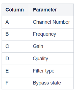
The exported file can be imported back to the panel using the import button.
8.2.CoefficientBiquad
The CoefficientBiquad audio object accepts biquad filter coefficients via its tuning interface and then filters signals accordingly. This audio object also adjusts the input audio buffers based on the bi-quadratic filter coefficients provided into it via tuning and stores the resulting audio in the output buffers.
Use Case: This object can be deployed whenever a user wants to filter a signal based on user specified coefficients.
CoefficientBiquad Properties
Below table describes about the CoefficientBiquad audio object properties and functionality.

| Properties | Description |
| # of Channels | The object has a configurable number of channels. The number of audio inputs is always equal to the number of audio outputs.
|
| Number of biquads | The number of elements generally describes the number of filters requested by the user. This value is configurable between 1 and a 100 and is by default set to 1. |
| Display Name | Display the name of the Adder audio object in signal flow design. It can be changed based on the intended usage of the object. |
Mode
There are no mode available for CoefficientBiquad audio object.
Additional Parameters
| Parameters | Description | |
| Biquad Topology | Allows to choose the filter topology at design time.
By default, it is configured for DFII. |
 |
| Coefficient Type | Allows to configurable object variable that indicates whether the filter coefficients are shared across all channels or not.
In this layout, the filter coefficients are unique per channel. The number of filters selected above would apply per channel in this layout. If the number of filters above is selected to be two, then two unique biquad sets of coefficients will be applied across each channel.
This layout will share a set of filter coefficients across all channels. If the number of filters above is selected to be two, then the same two biquad sets of coefficients will be applied across all channels. By default, it is configured for Coefficient. |
 |
Tuning Parameters
This object does not support state and control interfaces; it only supports a tuning interface.
The five values below represent filter coefficients per biquad. Coefficient Layout exposes five values per biquad per channel, whereas Coefficient One Layout exposes one set of coefficients per biquad, and these are shared across all channels.
| Parameter | Description | Type | Unit | Range | Default Value | Memory Offset |
| b0 | Biquad coefficient | float | None | 1 | f * 5 * 4 + 0 | |
| b1 | Biquad coefficient | float | None | 0 | f * 5 * 4 + 4 | |
| b2 | Biquad coefficient | float | None | 0 | f * 5 * 4 + 8 | |
| – a2 | Biquad coefficient | float | None | 0 | f * 5 * 4 + 12 | |
| – a2 | Biquad coefficient | float | None | 0 | f * 5 * 4 + 16 |
b are numerator coefficients and a is denominator. The coefficients are expected to be normalized (*1/a0). And a1 and a2 are expected to be negated before being passed in.

Control Parameters
There are no control parameters available for CoefficientBiquad audio object.
8.2.1.Coefficient Biquad Native Panel
Coefficient biquad native panel is launched for the Coefficient biquad audio object. The panel has two modes.
- Coefficient
- Parameter
Coefficient Mode
Panel contains channel drop-down and option to import and export coefficients. The panel has a chart that has only total amplitude and total phase graphs.

The “Send” button sends the biquad coefficients to the device. The biquads configured will show up with 5 coefficients each numbered 1 to n.
The coefficients will have default values 1,0,0,0,0.

Coefficients cannot be edited. It can be filled only by importing coefficients from a .csv file. The format of the file is shown below.

The current implementation will import coefficients to the biquads that are configured and leave the biquads that is not listed in the import file untouched. Please make sure you add default values to the ones that do not have coefficients.
Presets at the bottom to save different coefficient values are supported like any other native panels.
Parameter mode
In this mode, you can set parameters using filters, just like in the EQ Panel. Parameters for all channels can be exported and imported.

The “Calculate” button calculates all parameters to coefficients but does not send them to the device. It switches to Coefficient mode so that they can be checked and sent with the “Send” button.
It is not possible to calculate coefficients to parameters, so it is possible that the coefficients will be different than the parameters. That is, the parameter mode may not reflect the state of the device/coefficients. It is possible after loading parameters sets, reading data from device or importing coefficients.
8.3.Tone Control Extended
The ToneControlExtended audio object supports changing the filter parameters Frequency, Gain, Q, type of the filter and ramp time for each channel in Signal Flow Designer.
The tone control extended block can generate filters and their coefficients and then filtering audio signals passed to the audio block based on the calculated coefficients. The tone control extended object can have a variable number of channels and have one set of filter coefficients per element for all channels. It has an adjustable number of elements or cascaded filters.
Use Case: This audio object applies filter on all the channels. When filter parameters are changed during run time, the filter coefficients are gradually changed to target values using ramping. Linear interpolation is used for filter ramping. Filter coefficients are ramped after every pre-configured number of samples for ramping. This ramping is applied until filter coefficient reaches target value.
ToneControl Properties
Below table describes about the ToneControlExtended audio object properties and functionality.

| Properties | Description |
| # of Channels | Enter number of channels. The number of input channels is always equal to the number of output channels.
|
| Number of bands | Enter number of bands per channel.
|
| Display Name | Display the name of the ToneControlExtended audio object in signal flow design. It can be changed based on the intended usage of the object. |
Mode
There are no mode available for ToneControlExtended audio object .
Additional Parameters
| Parameters | Description | |
| Biquad Topology | It supports one additional configuration of Biquad topology which can be selected among the available topologies.
By default, it is configured for DFI. |
 |
| Block Control |
It supports additional configuration of Block Control which can be enabled or disabled by selecting between Block Control Disabled and Block Control Enabled. 0 = Block Control Disabled 1 = Block Control Enabled If it is enabled, Frequency, Quality and Gain control signals of each band are grouped into one control pin and need to be set as a tuple. This means that the AO setting those needs to make sure all the three values are available. By default, it is configured for Block Control Disabled. |
 |
Tuning Parameters
For each filter in the tone control, this object exposes these five tuning parameters to the GTT.
There are no control output and three control inputs per filter element. Using control inputs user can change cut off frequency, Gain and Quality factor.
| Parameter | Description | Tunable or Controllable | Unit | Range | Default |
| Frequency |
Filtering frequency to be applied Tuning Control |
Control/Tunable | Hz | 10 Hz – 20 kHz | 20 Hz |
| Gain |
Filter gain Tuning Control |
Control/Tunable | dB | -30 to + 50 dB | 0 dB |
| Quality |
Quality of the filtering coefficients Tuning Control |
Control/Tunable | None | 0.1 – 10 | 0.71 |
| Type | Filter type | Tuneable | None |
|
AllPass |
| RampTime | Ramp time for filter coefficient to adapt to new coefficient | Tunable | msec | 0 to 500 msec | 10.0 msec |
Control Parameters
There are no control parameters available for ToneControlExtended audio object .
8.3.1.Tone Control Extended Panel
The ToneControlExtended panel is to tune ToneControlExtended audio object. The state variables of ToneControlExtended audio object can be updated using this panel.
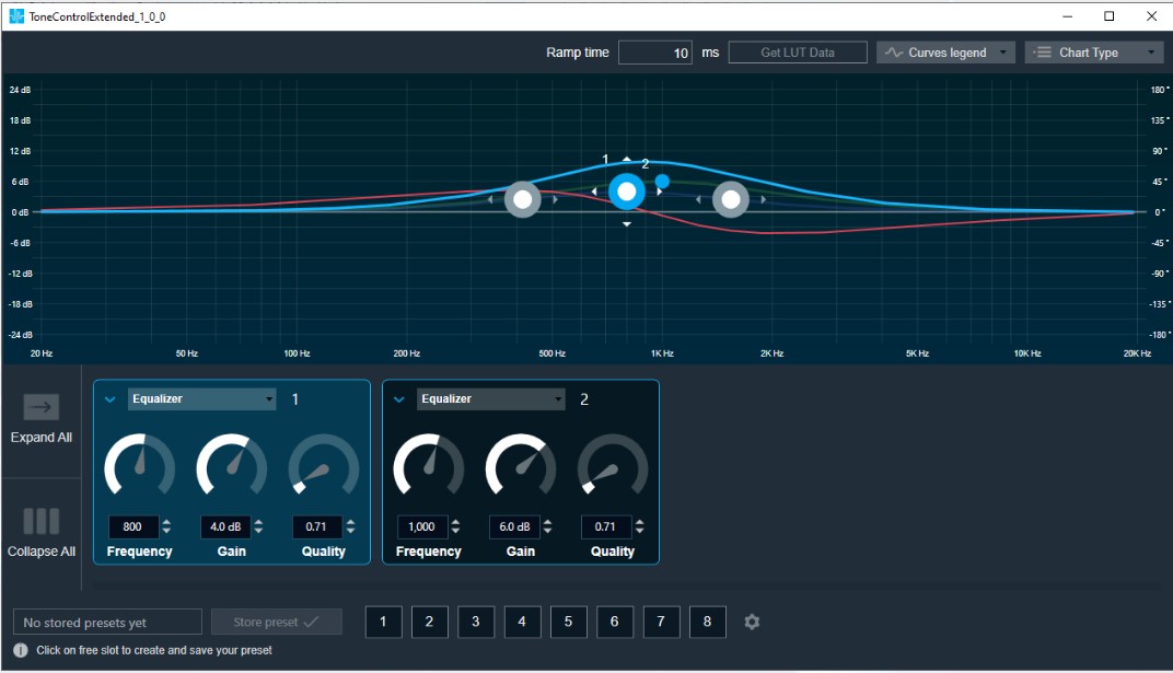
Tone Control Extended Chart
This chart represents the influence of all bands on the frequency and phase response. The left axis shows the amplitude in dB, the right axis shows the phase in degrees and the X-axis shows the gain.
The number of Bands are defined with the Signal Flow Designer. The Bands get dynamically managed inside the GTT. Most of the Bands are represented by appropriate markers.

Markers
Markers are movable. Moving them allows you to amend the current Band parameters. Each marker corresponds to one or two Band parameters. For example, the equalizer shown below has three markers.

Band Settings
On the Band settings window, you can perform the following operations.
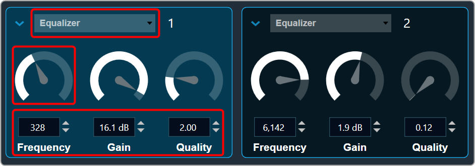
Change the Frequency, Gain, and Quality
Frequency: It is used to set the center frequency of each filter.
Gain: It is used to set the center frequency gain of each band of the filter. Not all filter types offer a variable gain.
Quality: It is used to set the width of each band pass or notch type band of the filter. Not all filter types offer a variable quality factor.
- Using the increase and decrease buttons
 you can change the value.
Or - Select the tuner and use mouse scroll to adjust the value.
All available filters are added, and default selection is set as All Pass 2 at panel startup.
Change Band type
The Band Filter menu shows a list of all Bands that are set up in the amplifier for the current channel. You can change the Biquad type or remove the Band by setting it to Bypass (at the top of the list).

Band Chart Type

Amplitude phase: It is used to turn on and off appropriate charts.
Phase Unwrapped: It displays absolute values.
- If the phase is wrapped, the display is limited to ± 180 °.
- If the phase exceeds 180 ° or -180 ° it is continued on the other side of the vertical scale.
Used Biquads: This informs you about the available Biquads. The first number is the number of Biquads that have not been bypassed. The second number is the number of available Biquads.
Sample rate: It shows the sample rate at which the filters are operated.
Band Curve Legend
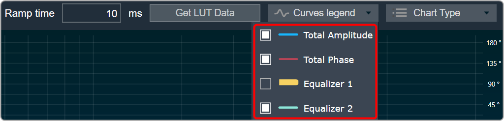
Click on Curve Legend to display all the associated legends. By default, all the curve legends are enabled on the graph. Uncheck the curve to hide it from the graph.
- Panel preset is used to store the tuning parameter.
- Ramp time is used to set the ramp characteristic of the object.
In Tone Control Extended Panel, there is no channel selector since the band values are the same across all the channels.
Get LUT data
When a Tone Control Extended is connected to the LUT objects, the Tone Control Extended Panel displays the graph for the LUT data.
These graphs are just for visualization, you cannot alter the graph values from the panel.
- Connect the LUT objects to Control pins of Tone Control Extended objects.

- Open LUT panel and set row, column name and values.
- Open Tone Control Extended panel and click Get LUT data. This will plot the graph for the LUT data.

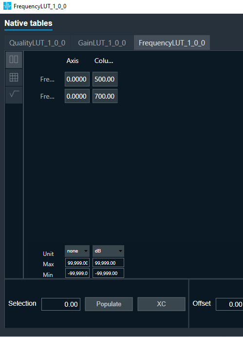


If any one pin is not connected to LUT in a particular band, then corresponding tuning value will be used to plot curve.
Curve Legend

- This is a movable control and can be expanded or collapsed. It can be moved anywhere within the panel.
- It has the following information: Filter Name, Band Number, Row Name, Frequency, Gain, Quality value.
- Ex: Equalizer 1 Frequency1 500 Gain 4 Quality 1
- Check box can be used to show/hide the specific curve
- When corresponding row name is not available we will mark with “—“. This means the data comes from Tuning data “Clear LUT data” will switch back to the previous mode.
“Get LUT data” is supported only when it is directly connected to the LUT object.
8.4.XoverBiquad
The XoverBiquad audio object computes crossover bi-quadratic filter coefficients and calculates the output of the input audio buffers processed through the filters that users specify.
Use Case: This object can be deployed whenever a user needs a crossover filter with specified parameters.
XoverBiquad Properties
Below table describes about the XoverBiquad audio object properties and functionality.

| Properties | Description |
| # of Channels | Enter number of channels. The object has a configurable number of channels as well as the number of filters. The number of audio inputs is always equal to the number of audio outputs.
In SFD, users can set the number of channels (the number of input and output channels is the same) as well as the number of filters. Users can also select the object corresponding to the required mode. |
| Number of biquads | The number of elements generally describes the number of filters requested by the user.
|
| Display Name | Display the name of the XoverBiquad audio object in signal flow design. It can be changed based on the intended usage of the object. |
Mode
There are no mode available for XoverBiquad audio object.
Additional Parameters
| Parameter | Description | |
| Biquad Topology | This audio object has an additional variable that allows you to pick the topology of the object at design time.
By default, the object uses DFII. |
 |
Tuning Parameters
| Parameter | Description | Tunable or Controllable | Range | Default |
| Frequency | Filtering frequency to be applied | Tunable | 10 Hz – 20 kHz | 1000 Hz |
| Type | Filter type | Tunable | The memory layout is exposed in GTT as (per filter).
|
BYP_XOVER |
| Bypass | Bypass enable or disable | Tunable | 0 – 1 | 0 |
Control Parameters
There are no control parameters available for XoverBiquad audio object.
8.4.1.Xover Biquad Panel
The XoverBiquad panel is to tune XoverBiquad audio object. The audio object computes crossover bi-quadratic filter coefficients in the Xover Biquad panel, which also computes the output of the input audio buffers processed through the filters that users specify for each channel.

Channel List
On the Xover Biquad panel, you have the option to choose a channel for the current core from a list located at the top left.

The current channel is marked with a green square and its number is displayed in the header of the channel list.
Xover Biquad Chart
This chart represents the influence of all Biquads on the frequency and phase response. The left axis shows the amplitude in dB, and the right axis shows the phase in degrees and the X- axis shows the gain.
The number of Biquads are defined with the Signal Flow Designer. The Biquads get dynamically managed inside the GTT. Most of the Biquads are represented by appropriate markers.

Markers
Markers are movable. Moving them allows you to modify frequency parameter.

Biquad Settings

Enabling Bypass
- Click on the
 Bypass button to enable or disable Bypass.
 - In bypassed state, the button is red colored and green colored when biquad is in non-bypassed state.
Biquad is in a bypassed state by default.
Even the higher order filter in Xover biquad only uses one biquad, so the number of bands assigned to the object will be equal to the number of biquads in the panel. Therefore, when the panel launches, it contains all of the biquads.
Change the Frequency, Gain, and Quality
Frequency: It is used to set the center frequency of each filter.
Gain: Gain is set to zero dB for all the filter types.
Quality: It is used to set the width of each band pass or notch type band of the filter. It is set to 0.58 for Bessel type filters, 0.50 for the LinkwitzRelay type filters and 0.71 for other types of filters.
- Using the increment and decrement buttons
 you can change the value.
Or
- Select the tuner and use mouse scroll to adjust the value
Change Biquad type
The Biquad Filter Menu shows a list of all Biquads that are set up in the amplifier for the current channel. You can change the Biquad type in the combo box.

You cannot add new filters to the Xover Panel. All available filters are added and bypassed at panel startup.
Xover Biquad supports Higher order filters, hence there is no necessity to merge nor split of biquads.
Biquad Chart Type

Amplitude phase: It is used to turn on and off appropriate charts.
Phase Unwrapped: It displays absolute values.
- If the phase is wrapped, the display is limited to ± 180 °.
- If the phase exceeds 180 ° or -180 ° it is continued on the other side of the vertical scale.
Used Biquads: This informs you about the available Biquads. The first number is the number of Biquads that have not been bypassed. The second number is the number of available Biquads.
Sample rate: It shows the sample rate at which the filters are operated.
This panel is supported from audio library version 13.0.0.2016 (M-release) onwards. After loading the library import the project again to launch the Xover panel.
Biquad Curve Legend

Click on Curve Legend to display all the associated legends. By default, all the curve legends are enabled on the graph. Uncheck the curve to hide it from the graph.
Export & Import
Biquad parameters can be exported by clicking the export button as csv in the below format.

The biquad parameters can be exported in the following format by clicking the export button as a CSV file.


The exported file can be imported back to the panel using the import button.
8.5.FastConv
This FastConv (Fast Convolution) audio object implements an N-channel point to point FIR filter with a constant number of taps for all channels. This filter is optimal for higher order filters (> 1000).
Coefficients are provided through GTT custom panel from pre-stored coefficient files in .csv format.
- Coefficients can be different for each channel, but with same tap length.
- Coefficients represent the impulse response of the filter in time domain.
Without loaded coefficients, the filter functions as an all-pass filter passing the input signal as it is.
The FastConv audio object supports in-place computation based on the core type.
Use Case: The computational effort of a simple FIR filter in time domain increases linearly with the number of taps used.
For complex wideband filtering, example low frequency filtering using room impulse responses – the number of used taps might easily reach few hundreds or thousands. As this number of FIR taps in time domain cannot be realized with reasonable computational effort, it makes sense to do convolution by multiplication in frequency domain – using the FFT.
The trade-off for using fast convolution depends on the used platform and might be in the area of 32-64 taps.
As this filter supports multiple channels – it can be used to adjust the sound to certain acoustics in a multichannel environment. The impulse response, i.e. the time domain coefficients can be different for each channel.
FastConv Properties
Below table describes about the FastConv audio object properties and functionality.

| Properties | Description |
| # of Channels | The object has a configurable number of channels. The number of audio inputs is always equal to the number of audio outputs.
|
| Number of taps | The object has a configurable number of taps.
|
| Display Name | Display the name of the FastConv audio object in signal flow design. It can be changed based on the intended usage of the object. |
Mode
There are no mode available for FastConv audio object.
Additional Parameters
There are no additional parameters available for FastConv audio object..
Tuning Parameters
In the current init setup, the tuning filter coefficients consist of all pass or bypass. In the real-world setup, these will be replaced with actual filter coefficients calculated for the preferred vehicle environment.
There are two sets of tuneable parameters –
- Mode: Mode is a single variable
- Coefficients: the number of coefficients depends on the tap-length value configured in GTT
Let Nc denote the number of coefficients (taps), Ni number of channels. All filter coefficients are stored using floating point format. The number of coefficients is rounded up to an integer power of 2, which allows for effective FFT radix-2 or radix-4 implementation. The filter coefficients are denoted by hi[k] where “I” is the filter’s index ranging from 0 to Ni−1 and “k” is the coefficient index (k = 0…Nc−1).
| Sub-block ID | Name | Description | Offset | Type | Unit | Range | Default |
|---|---|---|---|---|---|---|---|
| 0 | mode [0] | Mode for filter 0 | 0 | UInt32 | None | 0,1,2 | 0 |
| 0 | Coefficients for filter 0 | 4 | float | None | -1.0f; +1.0f | 1.0f | |
| 0 | Coefficients for filter 0 | 8 | float | None | -1.0f; +1.0f | 0.0f | |
| 0 | Coefficients for filter 0 | float | None | -1.0f; +1.0f | 0.0f | ||
| 0 | Coefficients for filter 0 | + 4 | float | None | -1.0f; +1.0f | 0.0f | |
| 1 | mode [1] | Mode for filter 1 | + 4 | UInt32 | None | 0,1,2 | 0 |
| 1 | Coefficients for filter 1 | + 8 | float | None | -1.0f; +1.0f | 1.0f | |
| 1 | Coefficients for filter 1 | + 8 | float | None | -1.0f; +1.0f | 0.0f | |
| 1 | Coefficients for filter 1 | float | None | -1.0f; +1.0f | 0.0f | ||
| 1 | Coefficients for filter 1 | + 12 | float | None | -1.0f; +1.0f | 0.0f | |
| Ni-1 | mode [Ni-1] | Mode for filter Ni-1 | + | UInt32 | None | 0,1,2 | 0 |
| Ni-1 | Coefficients for filter | + | float | None | -1.0f; +1.0f | 1.0f | |
| Ni-1 | Coefficients for filter | float | None | -1.0f; +1.0f | 0.0f | ||
| Ni-1 | Coefficients for filter | float | None | -1.0f; +1.0f | 0.0f | ||
| Ni-1 | Coefficients for filter | + | float | None | -1.0f; +1.0f | 0.0f |
The pre-computed FIR filter time domain coefficients need to be stored in a file in .csv format.
GTT has the provision to import the coefficients from the file for the selected channel and pass them to the device. During tuning phase, these time domain filter coefficients are converted to frequency spectrum coefficients for multiplication with the spectrum of the input.
The generalized offset information of the two tuneable parameters can be found below table.
FastConv Tuneable Parameters
| Sub-block ID | Name | Description | Offset | Type | Unit | Range | Default |
| i | mode[i] | Mode for filter i | UInt32 | – | 0,1,2 | 0 | |
| i | Coefficient k=0 for filter i | float | – | -1.0f; +1.0f | 1.0f | ||
| i | Coefficient k>0 for filter i | float | – | -1.0f; +1.0f | 0.0f |
FastConv operational mode (Normal / Bypass / Mute) can be controlled (as tuning parameters) from GTT panel. The description of each mode is given in the table below.
FastConv Mode Details
| Mode Value | Mode Tag | Description |
| 0 | NORMAL | Filter operation under use |
| 1 | BYPASS | Input buffer copied to output buffer |
| 2 | OFF | Output buffer set to zero |
Control Parameters
There are no control parameters available for FastConv audio object.
8.5.1.Fast Conv Panel
Fast Conv filter native panel allows you to configure the Mode of each enabled filter and to load coefficients as well. In order to see the graphs, you need to import coefficients. Use ‘Import’ or ‘Import All’ option to import coefficients.
To open the native panel, double-click on the Fast Conv filter audio object in the signal flow designer.

Amplitude/Phase: When the coefficients are given and “Amplitude/Phase” option is selected, the graph display the value.

Coefficients: When the coefficients are given and the “Coefficients” option is selected, the graph displays the values as per below figure. You can change the graph style using the “Chart Style” option.
| Line chart style: when “Chart Style” selected as Line, the Coefficients graph. | 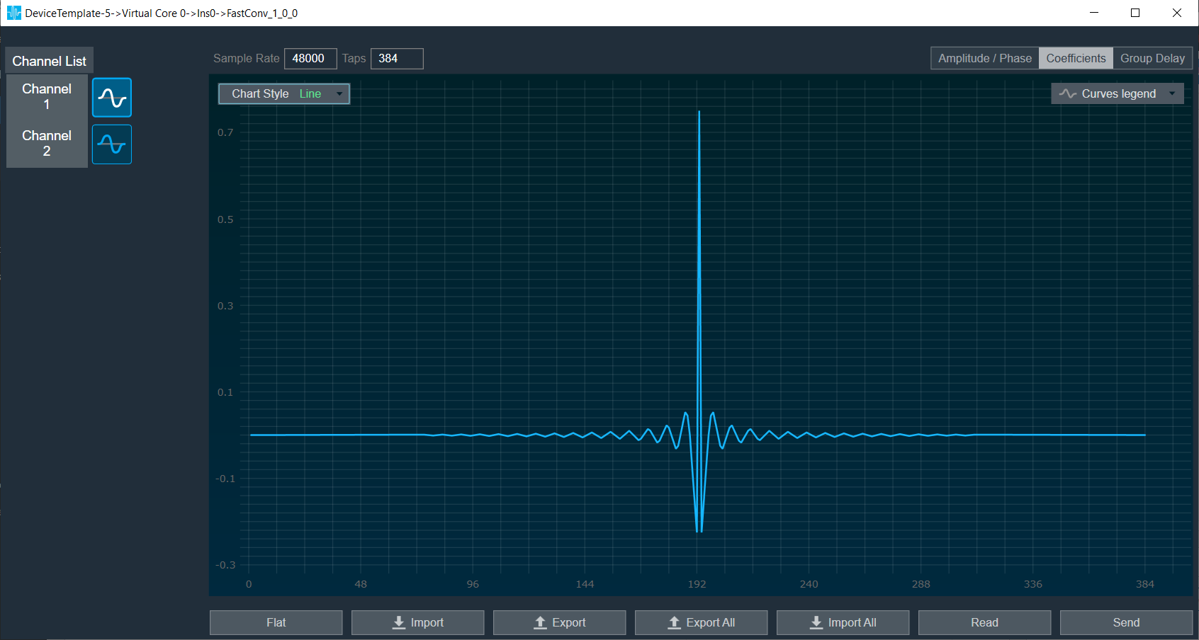 |
| Dot chart style: when “Chart Style” selected as Dot, the Coefficients graph. | 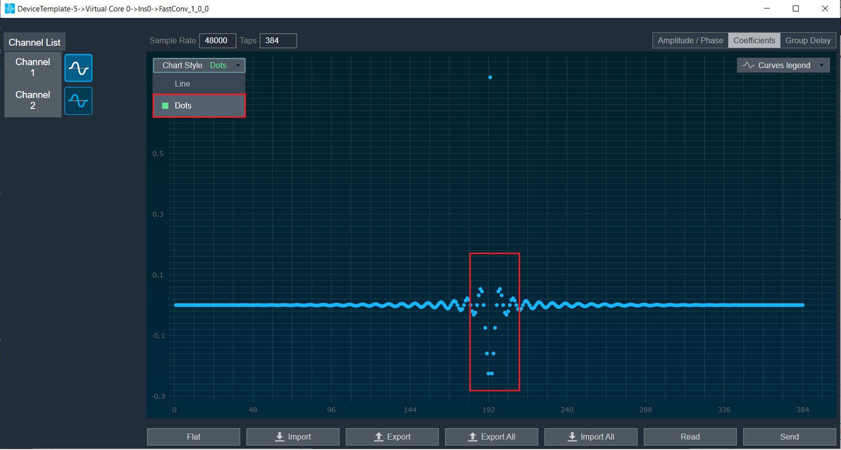 |
Group Delay: When the coefficients are given and “Group Delay” option is selected, the graph display the values.
Curves Legend: This option allows you to show the details of which graph tab (Amplitude/Phase, Coefficients, Group Delay) is selected.
| On the selection of Amplitude/Phase graph tab Curves Legend will show below information. |  |
| On the selection of Coefficients graph tab and Chart Styles ‘Dots’, Curves Legend will show below information. |  |
| On the selection of Coefficients graph tab and Chart Styles ‘Line’, Curves Legend will show information. |  |
| On the selection of Group Delay graph tab, Curves Legend will show information. |  |
Additional Functionalities
- Flat: This is used to make the graph flat by making coefficients to 0.
- Import: This function is used to import the coefficients for a single active filter. Click the “Import” button, then enter the file path and click Ok.
All coefficients for the selected filter will be imported, as shown in the graph. If the number of coefficients does not match the number of taps as shown in the screenshot below, a warning pop up will appear. Click ‘Yes’ to import available coefficients or click ‘No’ to cancel the import. - Export: This option is used to export coefficients for selected active filter into csv file.
- Export All: This option is used to export all active filters in one go. Click the “Export All” button, then enter the path and file name, then click Ok. A xml file will be created which will have coefficients for each active filter.
- Import All: This option is used to import all coefficients in one go. Click the “Import All” button, then enter the XML file path and click Ok. All the given coefficients will be imported and can be seen in the graph.
- Read: This is used to read from the target to display in the panel.
- Send: This is used to send the values changed in panel to target.
8.6.DC Blocker
The DC Blocker audio object is a simple first-order recursive highpass filter set to a very low corner frequency, such that DC offset is removed from the input.
Use Case: This object can be deployed wherever a DC blocking filter is needed.
DC Blocker Properties
Below table describes about the DC Blocker audio object properties and functionality.
| Properties | Description |
| # of Channels | The number of channels is configurable in GTT
|
| Display Name | Display the name of the DC Blocker audio object in signal flow design. It can be changed based on the intended usage of the object. |
Mode
There are no mode available for DC Blocker audio object.
Additional Parameters
There are no additional parameters available for DC Blocker audio object.
Tuning Parameters
| Parameter | Description | Unit | Format | Range | Default |
| Corner Frequency | Filter corner frequency. Attenuates frequencies below the corner frequency. Frequencies above corner frequency are not attenuated. | Hz | Float | 0.0 f to 20.0 f | 5.0 f |
Control Parameters
There are no control parameters available for DC Blocker audio object.
8.6.1.DC Blocker Panel
The DC blocker panel is used to change the corner frequency of filter for all channels.
This is a beta version of the panel and works only for a 1 channel use case in M release. Higher number of channels will be available in future releases.
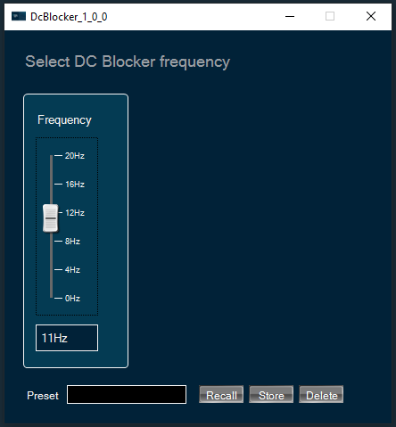
To change DC Blocker frequency
You can change the channel frequency by three ways:
- Using slider button: Select the slider to adjust the value.
- Using mouse scroll: Click on the respective column and use mouse scroll to adjust the value.
- Using text box: Enter the desired value into the text box located below the slider. The changes will be applied either by pressing the “Enter” key or by shifting the focus away from the text box.
8.7.FIR Filter
The FIR Filter audio object implements a mechanism for time domain FIR filtering. FIR filters are more stable than IIR filters and can be designed to have linear phase response. However, they require a filter of higher order for similar response as an IIR and hence computationally intensive.
The filter operational mode can be controlled from GTT. The FIR filter coefficients can be provided through GTT custom panel from pre-stored coefficient files in .csv format.
Use Case: FIR filters are mostly used in applications that require linear phase. They are inherently more stable than IIR filters. However, FIR filters are generally computationally intensive. The applications include:
- Correction of frequency response errors in a loudspeaker.
- Phase correction in communication lines.
- Parametric and crossover filters implemented with FIRs can be implemented with or without phase shift.
FIR Filter Properties
Below table describes about the FIR Filter audio object properties and functionality.

| Properties | Description |
| # of Channels | The FIR Filter audio object has a number of input channels that is double the number of output audio channels.
|
| Number of taps for filter | Specify the number of elements which is the order of filter.
|
| Display Name | Display the name of the FIR Filter audio object in signal flow design. It can be changed based on the intended usage of the object. |
Mode
| Mode | Description |
| Normal | The FIR Audio Object shall perform the normal filter operation individually for each channel with the set of coefficients provided for each channel. The filter type can vary for each channel but the number of coefficients of all channels need to be the same. |
| Bypass | The FIR Audio Object shall copy the input signal to the output buffer bypassing the filter operations. Each channel can be selectively bypassed. |
| Off | The FIR Audio Object clears the output buffers. |
Additional Parameters
There are no additional parameters available for FIR Filter audio object.
Tuning Parameters
There are two sets of tunable parameters – mode and coefficients.
- Mode is a single variable.
- The number of coefficients depends on the tap-length value configured in GTT.
Let Nc denote the number of coefficients (taps), Ni number of channels. All filter coefficients are stored using floating point format. The filter coefficients are denoted by hi[k] where “i” is the filter’s index ranging from 0 to Ni−1 and “k” is the coefficient index (k = 0…Nc−1).
The generalized offset information of the two tunable parameters can be found below table.
FIR Tunable Parameters Offset
| Name | Description | Offset | Type | Unit | Range |
| mode[i] | Mode for filter i | UInt32 | – |
|
|
| Coefficient k for filter i | float | – | -1.0f; +1.0f |
FIR Tuneable Parameters Default Values
| Name | Description | Default Values |
| Mode | Operational Mode | 0 – Normal |
| FIR Coefficients | FIR Coefficient Array input | [1.0f, 0.0f, 0.0f, ……… 0.0f] – All pass |
Control Parameters
There are no control parameters available for FIR Filter audio object.
8.7.1.FIR Filter Panel
FIR Filter native panel allows you to configure the Mode of each enabled filter and to load coefficients as well. In order to see the graphs, you need to import coefficients. Use ‘Import’ or ‘Import All’ option to import coefficients.
To open the native panel, double-click on the FIR Filter audio object in the signal flow designer.
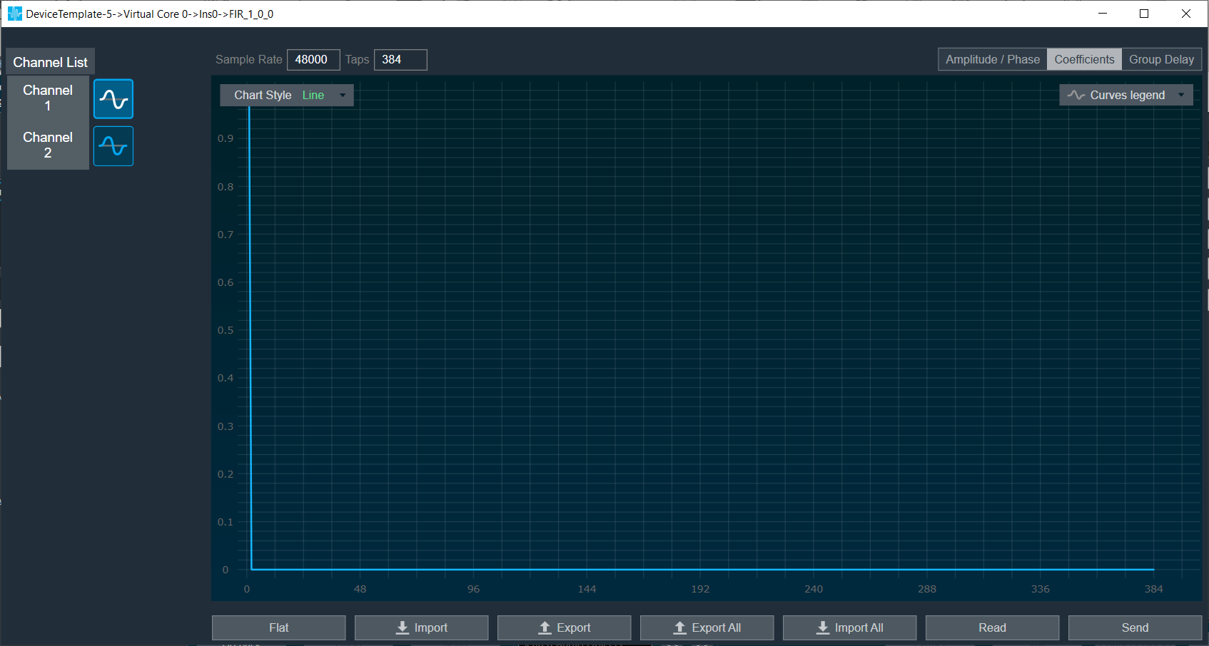
Amplitude/Phase: When the coefficients are given and “Amplitude/Phase” option is selected, the graph display the value.
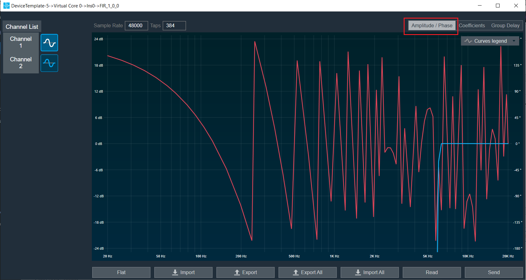
Coefficients: When the coefficients are given and the “Coefficients” option is selected, the graph displays the values as per below figure. You can change the graph style using the “Chart Style” option.
| Line chart style: when “Chart Style” selected as Line, the Coefficients graph. |  |
| Dot chart style: when “Chart Style” selected as Dot, the Coefficients graph. |  |
Group Delay: When the coefficients are given and “Group Delay” option is selected, the graph display the values.
Curves Legend: This option allows you to show the details of which graph tab (Amplitude/Phase, Coefficients, Group Delay) is selected.
| On the selection of Amplitude/Phase graph tab Curves Legend will show below information. | |
| On the selection of Coefficients graph tab and Chart Styles ‘Dots’, Curves Legend will show below information. | |
| On the selection of Coefficients graph tab and Chart Styles ‘Line’, Curves Legend will show information. | |
| On the selection of Group Delay graph tab, Curves Legend will show information. | |
Additional Functionalities
- Flat : This is used to make the graph flat by making coefficients to 0.
- Import : This function is used to import the coefficients for a single active filter. Click on the “Import” button, then enter the file path and click Ok.
All coefficients for the selected filter will be imported, as shown in the graph. If the number of coefficients does not match the number of taps, a warning pop up will appear. Click ‘Yes’ to import available coefficients or click ‘No’ to cancel the import. - Export : This option is used to export coefficients for selected active filter into csv file.
- Export All : This option is used to export all active filters in one go. Click on the “Export All” button, enter the path and file name, then click Ok. A xml file will be created which have coefficients for each active filter.
- Import All: This option is used to import all coefficients in one go. Click on the “Import All” button, enter the XML file path and then click Ok. All the given coefficients will be imported and can be seen in the graph.
- Read: This is used to read from the target to display in the panel.
- Send : This is used to send the values changed in panel to target.
8.8.FIR MIMO
The FIR MIMO audio object is a group of FIR filter banks associated with each input and output. They produce the preferred output signal to the speakers inside a vehicle, based on the input signals and the vehicle’s interior design.
Use case: FIR MIMO can be used for clever impulse and frequency optimization or applications such as individual sound zones.
FIR MIMO Properties
Below table describes about the FIRMIMO audio object properties and functionality.

| Properties | Description |
| # of Audio In | Enter the input value.
|
| # of Audio Out | Enter the output value.
|
| Number of taps for Hi filters | The number of filter coefficients (taps) for the high-rate path is configured using the m_NumElements. All channels in the high-rate path use the same number of taps.
|
| Display Name | Display name of the FIRMIMO audio object in signal flow design. It can be changed based on the intended usage of the object. |
Mode
The FIR MIMO audio object supports two modes of operation.
- Dual Rate mode
- ISZ mode

| Mode | Description |
| Dual Rate mode | In the GTT interface, you can select the number of filter taps and filter combinations. The default (and minimum) number of taps for the high-rate filters is set to 384. |
| ISZ mode |
In the ISZ mode, the object acts as a single rate (high rate) FIR MIMO object for accomplishing ISZ (Individual Sound Zones). For ISZ, the low rate path of FIR MIMO block is disabled, and the high rate path delay is fixed to zero. In addition, all the filter combinations are active by default for ISZ mode. You do not need to individually configure the additional configuration matrix to set the filter in each combination. Even though the m_AdditionalConfig parameters do not indicate that all the filters are active, the active filters can be viewed when we open the tuning panel for this object. The filter tap length should is fixed to 4096 only. This size must be fixed by you each time you switch to ISZ mode. This will be changed in future; where filter taps will be directly fixed by GTT when ISZ mode is selected. The max delay for hi rate filters will also be set to 0 only. These filters are designed using a highly specialized tuning algorithm, known as MFxLMS (Multiple Filtered Input Signal Least Mean square). Several constraints such as pre-ringing and post-ringing, frequency and phase constraints are applied to allow the CTC filter networks to be realizable with FIR taps to provide the desired response. There are two stages in the ISZ algorithm:
|
Additional Parameters
Below table describes about the FIR MIMO audio object properties and functionality.
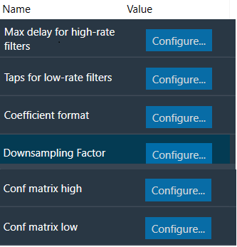
| Parameter | Description | |
| Max delay for high-rate filters | Length of delay line for high-rate path.
|
 |
| Taps for low-rate filters | Number of taps for low-rate filters. All channels in the low-rate path use the same number of taps which can be different from high rate.
|
 |
| Coefficient format | Filter coefficient data format.
Note: When 16-bit fixed point format(Q15 format) is selected the filter coefficients should be in range of -1.0 to 1.0 |
 |
| Downsampling factor | Downsampling factor for low rate filters
|
 |
| Conf matrix high | Configuration matrix for high-rate filters.
Value:
|
 |
| Conf matrix low | Configuration matrix for low-rate filters.
Value:
|
 |
Tuning Parameters
For each filter combination in FIR MIMO, this object exposes these two tuning parameters to the GTT:
| Parameter | Description |
| Mode | The parameter is of the category “State” and therefore, the configurations done for Filter modes will be transferred to device only after device is connected. The mode of each filter can be set to:
|
| Coefficients | Filter coefficients can be imported from .csv files. The filter taps set in the GTT must match the taps of the filter being imported from the .csv file. |
Control Parameters
There are no control parameters available for FIR MIMO audio object.
8.8.1.FIR MIMO Panel
FIR MIMO native panel allows you to configure the Mode of each enabled filter and to load coefficients as well. All the diagonal filters are active as these diagonal values are configured through additional parameters. In order to see the graphs, you need to import coefficients. Use ‘Import’ or ‘Import All’ option to import coefficients.
To open the native panel, double-click on the FIR MIMO audio object in the signal flow designer.

When the device is connected the filter states will not be in sync with the device until the states are received or the native panel is opened. Once the native panel is opened after a successful connection, the filter states will be transferred to the device.
Provide number of Taps to 384 and from additional parameters set all diagonal cell to 1 for Conf matrix high/ low as per below image.

Amplitude/Phase: When the coefficients are given and “Amplitude/Phase” option is selected, the graph display the value as per below figure.

Coefficients: When the coefficients are given and “Coefficients” option is selected, the graph display the values as per below figure. You can change the graph style using “Chart Style” option.
| Line chart style: When “Chart Style” selected as Line, the Coefficients graph as per image. |  |
|
Dot chart style: When “Chart Style” selected as Dot, the Coefficients graph as per below image.
|
 |
Group Delay: When the coefficients are given and “Group Delay” option is selected, the graph display the values as per below figure.

Curves Legend: This option allows you to show the details of which graph tab (Amplitude/Phase, Coefficients, Group Delay) is selected.
|
On the selection of Amplitude/Phase graph tab Curves Legend will show below information.
|
 |
|
On the selection of Coefficients graph tab and Chart Styles ‘Dots’, Curves Legend will show below information.
|
 |
|
On the selection of Coefficients graph tab and Chart Styles ‘Line’, Curves Legend will show below information.
|
 |
|
n the selection of Group Delay graph tab, Curves Legend will show below information.
|
 |
Additional Functionalities
- Flat: This is used to make the graph flat by making coefficients to 0.
|
Before you use “Flat” functionality.
|
After you click on the “Flat” button, the graph will change as per below image.
|


- Import : This function is used to import the coefficients for a single active filter. Click on the “Import” button, enter the file path and then click Ok. All coefficients for the selected filter will be imported, as shown in the graph. If the number of coefficients does not match the number of taps as shown in the screenshot below, a warning pop up will appear. Click ‘Yes’ to import available coefficients or click ‘No’ to cancel the import.

- Export : This option is used to export coefficients for selected active filter into csv file.

- Export All : This option is used to export all active filters in one go. Click on the “Export All” button, enter the path and file name, then click Ok. A xml file will be created which have coefficients for each active filter. Below figure shows the example of the configuration of the active filters in the xml file. You can use “Import All’ button to import back the exported file.

- Import All : This option is used to import all coefficients in one go. Click on the “Import All” button, enter the XML file path and then click Ok. All the given coefficients will be imported and can be seen in the graph. If there is a mismatch between xml file In and Out matrix with FIRMIMO panel In and Out matrix then error will be displayed and import will fail. In below image filter (Out 1 In1) is not active and try to import this as well so error is prompted.

- Read: This is used to read from the target to display in the panel.
- Send: This is used to send the values changed in panel to target.
Above mentioned functionality is similar for LowRate tab as well.
Memory allocation for optimized MCPS on SHARC Platform
The FIRMIMO audio object has memory records for FFT of input and output signals and scratch memory record used for Ping Pong Buffers for data and coefficients (SHARC platform) and temporary buffers for upsampler/downsampler. The MCPS performance depends on allocation of these buffers to lower memory latency levels.
- For FIRMIMO memory latency is pre-allocated in code for certain memory records in SHARC platform.
- For memory record for FFT of input buffers (memory record label: Input Signal FFT), Level1 is assigned.
- For memory record for FFT of output buffers (memory record label: Output Signal FFT), Level2 is assigned.
Level 1 latency is assigned to Ping Pong Buffers for Data (memory record label: Data PingPong Buffer) and Scratch Memory Record.

8.9.FIRA MIMO
FIRA MIMO audio object is a group of FIR filter banks associated with each input and output. FIRA stands for “fir accelerator” and it indicates that the underlying implementation uses a hardware accelerator. MIMO stands for “multi-input multi output” indicating that each output is the summation of one or more FIR filtered inputs.
FIRA MIMO can be used for various applications like individual sound zones etc.
Use Case: This audio object can be deployed whenever the audio requires the dual rate MIMO FIR filters taking into consideration the data pipeline delay and other limitations.
More than one instance of FIRAMIMO also can be run in the same core .
This AO supports in-place computation based on the core type.
FIRA MIMO Properties
Below table describes about the FIRAMIMO audio object properties and functionality.

| Properties | Description |
| # of Audio In | Enter the input value.
|
| # of Audio Out | Enter the output value.
|
| Number of taps for Hi filters | The number of filter coefficients (taps) for the high-rate path is configured using the m_NumElements. All channels in the high-rate path use the same number of taps.
|
| Display Name | Display name of the FIRAMIMO audio object in signal flow design. It can be changed based on the intended usage of the object. |
Mode
There are no modes available for FIRA MIMO.
Additional Parameters
Below table describes the FIRA MIMO additional parameters.

| Parameter | Description | |
| Max delay for high-rate filters | Length of delay line for high-rate path.
|
 |
| Taps for low-rate filters | Number of taps for low-rate filters. All channels in the low-rate path use the same number of taps which can be different from high rate.
|
 |
| Coefficient format | Filter coefficient data format.
|
 |
| Down sampling Factor | Down sampling factor.
|
 |
| Conf matrix high | Configuration matrix for high-rate filters.
Value:
|
 |
| Conf matrix low | Configuration matrix for low-rate filters.
Value:
|
 |
| Max Processing Size |
When 2 or more filters are enabled on an input channel, FIRAMIMO combines them and submits as one job to the accelerator. Max Processing Size is used as the max limit when combining. For example, when there are 6 filters enabled on an input channel and Max Processing Size is set to 4, FIRAMIMO submits the first job for 4 filters and second job with 2 filters.
|
 |
| Enable Cycles Measurement | Enable/Disable realtime accelerator mcps (million cycles per second). When enabled, Average and Max mcps are available to be read as tuning parameters in sate variable explorer.
|
 |
| Accelerator Configuration | Select which among the available FIR hardware accelerator to use for the FIR processing.
Range: 0 to 2 Default: 0 Data Type: uint8_t On ADSP-21593, when this configuration is set to Accelerator 1, only the first accelerator will be used, when set to Accelerator 2, only the second accelerator will be used, and when set to Both Accelerators, both available FIR accelerators will be used with almost equal number of filters processed by both accelerators. When both hardware accelerators are used:
On DSPs with only a single accelerator such as the ADSP-21569 (GUL), selection of accelerator configuration will be available, however, all filtering jobs will be processed by the only available FIR accelerator.
|
|


Tuning Parameters
For each filter combination in FIRA MIMO, this object exposes these two tuning parameters to the GT.
| Mode | Description |
| Mode | The mode of each filter can be set to:
This parameter is of the category “State” and therefore, the configurations done for Filter modes will be transferred to the device only after the device is connected. |
| Coefficients | Filter coefficients can be imported from .csv files. The filter taps set in the GTT must match the taps of the filter being imported from the .csv file. |
Control Parameters
There are no control parameters available for FIRA MIMO.
Memory Allocation Considerations for SHARC ADSP-21593 Platform in Dual Accelerator Mode
When using the FIRAMIMO object on a SHARC ADSP-21593 in dual accelerator mode, careful memory record placement consideration is required to maximize the number of FIR filters that can be processed. The hardware FIR accelerators in the DSP perform operations in parallel with the cores, causing memory access bottleneck due to the increase in the number of parallel memory accesses to the external memory (DDR3). This can be attributed to the page management overheads incurred by the Dynamic Memory Controller (DMC) as described in the EE-412 document, which adversely impacts the FIR accelerator performance, limiting the total number of FIR filters that can be processed by the AO. In order to mitigate the issue and improve the processing capacity of the accelerators, it is recommended that the input, output and filter coefficient buffers accessed by each accelerator are placed in dedicated DDR3 memory banks.
To enable placement of the buffers in separate banks, when the “Accelerator Configuration” additional configuration parameter is set to 2 (Both Accelerators), a new set of additional memory records with the prefix “(Acc 2)” are created to accommodate the second FIR accelerator’s input, output and coefficient buffers. The following figure shows the Memory Latency window in GTT highlighting the newly created memory records:
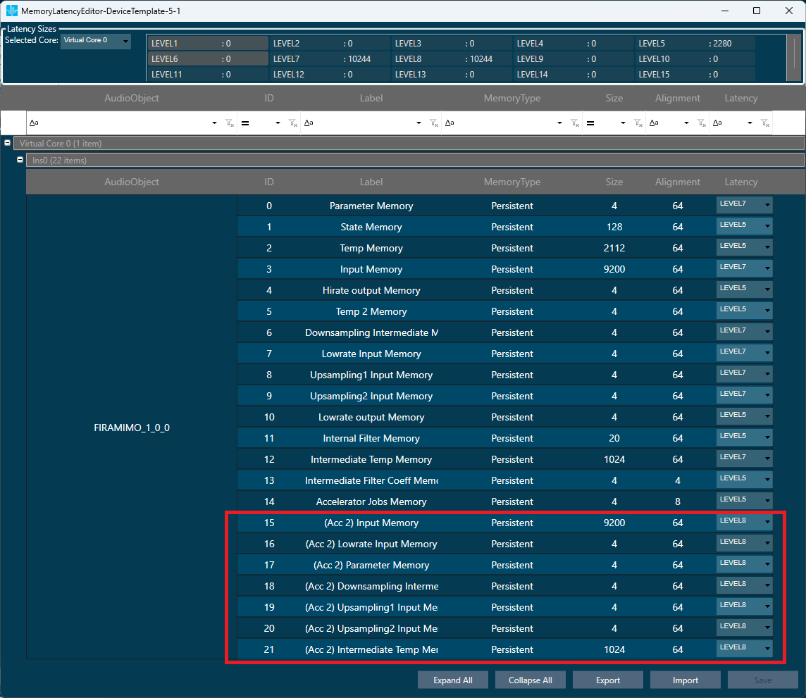
In this configuration, following are the memory records accessed by the accelerators:
| Hardware FIR Accelerator 1 | Hardware FIR Accelerator 2 | Description | |
| 1 | Input Memory | (Acc 2) Input Memory | High rate input buffers |
| 2 | Lowrate Input Memory | (Acc 2) Lowrate Input Memory | Low rate input buffers |
| 3 | Parameter Memory | (Acc 2) Parameter Memory | Filter coefficient buffers |
| 4 | Downsampling Intermediate Memory | (Acc 2) Downsampling Intermediate Memory | Downsampling filter output buffers |
| 5 | Upsampling 1 Input Memory | (Acc 2) Upsampling 1 Input Memory | Stage 1 upsampling filter input buffers |
| 6 | Upsampling 2 Input Memory | (Acc 2) Upsampling 2 Input Memory | Stage 2 upsampling filter input buffers |
| 7 | Intermediate Temp Memory | (Acc 2) Intermediate Temp Memory | Temporary memory for coefficient format conversion |
As per the recommendation, notice in the above figure that the memory records accessed by accelerator 1 are all placed in Level 7 memory latency, and the memory records accessed by accelerator 2 are all placed in Level 8 memory latency. It is expected that the platform maps these memory latency levels to un-cached memory regions that are in separate DDR3 memory banks in order to fully realize the separation of buffers.
At 512 sample block length, with 2k-tap high rate filters, following are the improvements observed in the total number of filters that can be processed by the FIRAMIMO AO in single vs dual accelerator modes:
- All accelerator buffers placed in Level 5 latency: 20% (32 filters to 40 filters).
- Accelerator 1 buffers in Level 7 and accelerator 2 buffers in Level 8, mapped to separate DD3 banks: ~90% (32 filters to 60 filters).
It is important to note that the separation of the memory records for the hardware FIR accelerators, however, increases the core MIPS consumption by about 30-60% in both single and dual accelerator modes due to additional buffer movement and summation operations done by the core to reduce the memory access overheads.
Note:
FIRAMIMO gives clear output in GUL, IVP but is distorted on HDP+ platform when ‘Input memory’ and ‘Upsampling1 input memory’ records are kept in Level4 or Level5, due to cache flush issue on HDP+ platform. The workaround is to keep these two memory records in Level1 to Level3.

8.9.1.FIRA MIMO Panel
FIRA MIMO native panel allows you to configure the Mode of each enabled filter and to load coefficients as well. All the diagonal filters are active as this diagonal values are configured through additional parameters. In order to see the graphs, you need to import coefficients. Use ‘Import’ or ‘Import All’ option to import coefficients.
To open the native panel, double-click on the FIRMIMO audio object in the signal flow designer.

When the device is connected the filter states will not be in sync with the device until the states are received or the native panel is opened. Once the native panel is opened after a successful connection, the filter states will be transferred to the device.
Provide number of Taps to 384 and from additional parameters set all diagonal cell to 1 for Conf matrix high/ low as per below image.

Amplitude/Phase: When the coefficients are given and “Amplitude/Phase” option is selected, the graph display the value as per below figure.

Coefficients: When the coefficients are given and the “Coefficients” option is selected, the graph displays the values as per below figure. You can change the graph style using the “Chart Style” option.
- Line chart style: when “Chart Style” selected as Line, the Coefficients graph as per below image.
- Dot chart style: when “Chart Style” selected as Dot, the Coefficients graph as per below image.
Group Delay: When the coefficients are given and “Group Delay” option is selected, the graph display the values as per below figure.

Curves Legend: This option allows you to show the details of which graph tab (Amplitude/Phase, Coefficients, Group Delay) is selected.
- On the selection of Amplitude/Phase graph tab Curves Legend will show below information.
- On the selection of Coefficients graph tab and Chart Styles ‘Dots’, Curves Legend will show below information.
- On the selection of Coefficients graph tab and Chart Styles ‘Line’, Curves Legend will show below information.
- On the selection of Group Delay graph tab, Curves Legend will show the information below.
Additional Functionalities
- Flat : This is used to make the graph flat by making coefficients to 0.
|
Before you use “Flat” functionality.
|
After you click on the “Flat” button, the graph will change as per below image.
|


- Import : This function is used to import the coefficients for a single active filter. Click on the “Import” button, enter the file path and then click Ok.
All coefficients for the selected filter will be imported, as shown in the graph. If the number of coefficients does not match the number of taps as shown in the screenshot below, a warning pop up will appear. Click ‘Yes’ to import available coefficients or click ‘No’ to cancel the import.

- Export : This option is used to export coefficients for selected active filter into csv file.

- Export All : This option is used to export all active filters in one go. Click on the “Export All” button, then enter the path and file name, then click Ok.
A xml file will be created which have coefficients for each active filter. Below figure shows the example of the configuration of the active filters in the xml file. You can use Import All’ button to import back the exported file.
- Import All: This option is used to import all coefficients in one go. Click on the “Import All” button, enter the XML file path and then click Ok.
All the given coefficients will be imported and can be seen in the graph. If there is a mismatch between xml file In and Out matrix with FIRMIMO panel In and Out matrix then error will be displayed, and import will fail. In below image filter (Out 1 In1) is not active and try to import this as well so error is prompted.

- Read: This is used to read from the target to display in the panel.
- Send : This is used to send the values changed in panel to target.
Above mentioned functionality is similar to LowRate tab as well.
9.Surround Objects
Surround objects category contains following audio objects.
9.1.CFQLS/CFQLI
The CFQLI (Clarifi and Quantum Logic Immersion) is combination of two different audio objects for purpose of optimization.
- Clari-Fi (CF) is an algorithm that receives a stereo audio stream, analyses the content for fidelity losses related to destructive or perceptual coding, then adds an approximation of these losses back to the original signal.
- Quantum Logic Immersion (QLI) is an up-mixing algorithm that converts the stereo or multichannel (5.1 or 7.1) input signals and up mixes it to 8 or 13 output channels (7.1 surround and 5 height channels).
CFQLI (Clarifi and Quantum Logic Immersion) also know as CFQLS (Clarifi and Quantum Logic Surround).
Use Case: The CFQLS object can used in following ways.
- CFQLS object can be used as standalone CF, standalone QLi or a combined CFQLS object.
- CF needs to process raw audio signal. Hence, it must be placed before any equalization (volume, compressor etc) in the signal flow. CF works only for stereo inputs and generates a stereo output. When both CF and QLS are to be used, the stereo output of CF is used as a stereo input of QLI.
CFQLS/CFQLI Properties
Below table describes about object properties and functionality of CFQLS/CFQLI audio object.

In the default mode, CFQLS object has no control inputs. It has 2 inputs and 13 output channels. The number of input and output channels for CFQLS can be controlled at design time by selecting the appropriate object mode.
| Properties | Description |
| Display Name | Display the name of the CFQLS audio object in signal flow design. It can be changed based on the intended usage of the object. |
| Object Mode | CFQLS supports following audio objects
|
Mode
There are total six mode in CFQLS object.
| Name | Description |
| 2.0_to_7.1.5 | Supports stereo input and generates 7.1 output plus 5 height channels. |
| 5.1_to_7.1.5 | Supports stereo and 5.1 input and generates 7.1 output plus 5 height channels. |
| 7.1_to_7.1.5 | Supports stereo, 5.1 and 7.1 input and generates 7.1 output plus 5 height channels. |
| 2.0_to_7.1 | Supports stereo input and generates 7.1 output. |
| 5.1_to_7.1 | Supports stereo and 5.1 input and generates 7.1 output. |
| 7.1_to_7.1 | Supports stereo, 5.1 and 7.1 input and generates 7.1 output. |
The input channel modes:
- Stereo
- Multichannel_5_1
- Multichannel_7_1
- Stereo_Ctrl
- Multichannel_5_1_Ctrl
- Multichannel_7_1_Ctrl
The QLS/QLI creates a 7.0.5 surround upmix from a stereo (or dual mono), 5.1, or 7.1 input audio signal using signal extraction and reverb extraction techniques.
Cross gains to x (front, center, side) are not applied on the dedicated multi-channel inputs (from input multi-channel signal), but only on the extracted channels as the result of the “Front signal extraction” feature, which needs to be enabled in the GUI. Currently, the original signals with cross gains are only applied to the front left and front right.
Memory allocation for optimized MCPS on GUL.
CFQLS algorithm uses FFT algorithm. There are six buffers used by FFT. For FFT to work these buffers must be allocated in internal memory. There are also memory alignment requirements.
Please refer below table for memory records and alignment.
| Memory record Label | Alignment in bytes |
| FFT real Input signal critical for MCPS |
4096 for Block size = 512 2048 for Block size = 256 |
| FFT imaginary input signal critical for MCPS |
4096 for Block size = 512 2048 for Block size = 256 |
| FFT temporary buffer1-critical for MCPS | 8 |
| FFT temporary buffer2-critical for MCPS | 8 |
| FFT Twiddle real part critical for MCPS | 8 |
| FFT Twiddle imaginary part critical for MCPS | 8 |
For better MCPS performance allocate these buffers to lower memory latency levels. MCPS can be further improved if these buffers are placed in different block of lower memory latency.
In xAF design:
- Level1 latency is mapped to L1 memory Block 0
- Level2 latency is mapped to L1 memory Block 1
- Level3 latency is mapped to L1 memory Block 2
Below is example of memory allocation for improved MCPS performance.

Additional Parameters
| Parameter | Description | Unit | Range | Default |
| Max Reverb Delay | The selected value sets the upper limit for the reverb delay tuning parameters. The value is used to enable a further reduction of the required memory as the size of reverb delays are influencing the required data memory. Values below 10ms are possible for maximum optimization but may lead to reduced audio performance | ms | 0 – 50 | 50 |
| Max Lookahead Delay | The selected value sets the upper limit for super user’ lookahead delay tuning parameter. The value is used to enable a further reduction of the required memory as the size of early reflections delays are influencing the required data memory. Values below 10ms are possible for maximum optimization but may lead to reduced audio performance | ms | 0 – 75 | 75 |
| Max Early Reflections Delay | The selected value sets the upper limit for the early reflections delay tuning parameters. The value is used to enable a further reduction of the required memory as the size of early reflections delays are influencing the required data memory. | ms | 0 – 2 | 2 |
| Enable/Disable swoosh | This configuration parameter enables or disables swoosh effect.
Disabling swoosh can further reduce required memory and has a large impact on CPU load, especially peak load when switching between settings |
– | 0 – 1 | 1 |
| Enable/Disable control inputs | Control inputs can optionally be enabled during design time.
Slightly more memory is required when control inputs are enabled |
– | 0 – 1 | 0 |
Tuning Parameters
CFQLS/CFQLI can be tuned by a comprehensive GTT tuning panel. Since the CFQLS object consists of two major algorithms, the tuning parameter list contains tuning parameters for QLS and CF algorithms.
Below table describe supported tuning parameters.
Control Parameters
CFQLS has 21 control inputs when the control mode is selected in GTT. The order of Control inputs for CFQLS.
| Channel | Description | Range |
| 1 | Front to Front Crossgain (Xgain_F2F) | 0 to 1 |
| 2 | Front to Center Crossgain (Xgain_F2C) | 0 to 1 |
| 3 | Front to Side Crossgain (Xgain_F2S) | 0 to 1 |
| 4 | Front to Rear Crossgain (Xgain_F2R) | 0 to 1 |
| 5 | Center to Front Crossgain (Xgain_C2F) | 0 to 1 |
| 6 | Center to Center Crossgain (Xgain_C2C) | 0 to 1 |
| 7 | Center to Side Crossgain (Xgain_C2S) | 0 to 1 |
| 8 | Center to Rear Crossgain (Xgain_C2R) | 0 to 1 |
| 9 | Side to Front Crossgain (Xgain_S2F) | 0 to 1 |
| 10 | Side to Center Crossgain (Xgain_S2C) | 0 to 1 |
| 11 | Side to Side Crossgain (Xgain_S2S) | 0 to 1 |
| 12 | Side to Rear Crossgain (Xgain_S2R) | 0 to 1 |
| 13 | Rear to Front Crossgain (Xgain_R2F) | 0 to 1 |
| 14 | Rear to Center Crossgain (Xgain_R2C) | 0 to 1 |
| 15 | Rear to Side Crossgain (Xgain_R2S) | 0 to 1 |
| 16 | Rear to Rear Crossgain (Xgain_R2R) | 0 to 1 |
| 17 | Wrap Control | 1 to 2 |
| 18 | Global Reverb Gain Control | 0 to 2 |
| 19 | Front Reverb Gain | 0 to 2 |
| 20 | Side Reverb Gain | 0 to 2 |
| 21 | Rear Reverb Gain | 0 to 2 |
9.1.1.CFQLS/CFQLI Panel
The CFQLS audio object has native panel. The native panel window has different controls for enabling and disabling various modes and for configuring tuning parameters. Native panel can be opened by double-clicking on the CFQLS object in the SFD.
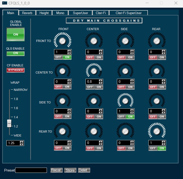
9.2.QLS/QLI
The QLI (Quantum Logic Immersion) is an up-mixing algorithm that converts the stereo or multichannel (5.1 or 7.1) input signals and up mixes it to 8 or 13 output channels (7.1 surround and 5 height channels) using signal extraction and reverb extraction techniques.
QLI (Quantum Logic Immersion) also know as QLS (Quantum Logic Surround).
Use Case: QLS object can be used as standalone QLi or in combination with Clarifi technology. CF needs to process raw audio signal. Hence, it must be placed before any equalization (volume, compressor etc) in the signal flow. CF works only for stereo inputs and generates a stereo output. When both CF and QLS are to be used, the stereo output of CF is used as a stereo input of QLI.
QLS/QLI Properties
Below table describes about the QLS/QLI audio object properties and functionality.

In the default mode, QLS object has no control inputs. It has 2 or 6 or 8 inputs and 8 or 13 output channels. The number input and output channels for QLS can be controlled at design time by selecting the appropriate modes of the object.
| Properties | Description |
| Display Name | Display the name of the QLS audio object in signal flow design. It can be changed based on the intended usage of the object. |
| Object Mode |
|
Mode
There are total six mode in QLS object.
| Name | Description |
| 2.0_to_7.1.5 | Supports stereo input and generates 7.1 output plus 5 height channels. |
| 5.1_to_7.1.5 | Supports stereo and 5.1 input and generates 7.1 output plus 5 height channels. |
| 7.1_to_7.1.5 | Supports stereo, 5.1 and 7.1 input and generates 7.1 output plus 5 height channels. |
| 2.0_to_7.1 | Supports stereo input, and 21 Control inputs and generates 7.1 output. |
| 5.1_to_7.1 | Supports stereo and 5.1 input, and 21 Control inputs and generates 7.1 output. |
| 7.1_to_7.1 | Supports stereo, 5.1 and 7.1 input, and 21 Control inputs and generates 7.1 output. |
The input channel modes are:
- Stereo
- Multichannel_5_1
- Multichannel_7_1
- Stereo_Ctrl
- Multichannel_5_1_Ctrl
- Multichannel_7_1_Ctrl
The QLI creates a 7.0.5 surround upmix from a stereo (or dual mono), 5.1, or 7.1 input audio signal using signal extraction and reverb extraction techniques.
Additional Parameters
| Parameter | Description | Unit | Range | Default |
| Max reverb delay | upper limit for the reverb delay | ms | 0 – 50 | 50 |
| Max lookahead delay | upper limit for super user lookahead delay | ms | 0 – 75 | 75 |
| Max early reflections delay | upper limit for the early reflections | ms | 2 – 0 | 2 |
| Enable/Disable swoosh |
1 – swoosh enabled 0 – swoosh disabled |
– | 1 | |
| Enable/Disable Reverb |
1 – Reverb enabled 0 – Reverb disabled |
– | 1 | |
| Enable/Disable control inputs |
0 – Control Inputs disabled 1 – Control Inputs enabled |
0 |
- supported block lengths of 512, 256
- supported sampling frequency of 48 kHz.
- this audio object supports a block length of 256 for reduced MEM and MIPS consumption.
Cross gains to x (front, center, side) are not applied on the dedicated multi-channel inputs (from input multi-channel signal), but only on the extracted channels as the result of “Front signal extraction” feature, which needs to be enabled in the GUI. Currently the original signals with cross gains are only applied to front left and front right.
Memory allocation for optimized MCPS on GUL.
QLS algorithm uses FFT algorithm. There are six buffers used by FFT. For FFT to work these buffers must be allocated in internal memory. There are also memory alignment requirements.
Please refer below table for memory records and alignment.
| Memory record Label | Alignment in bytes |
| FFT real Input signal critical for MCPS” |
4096 for Block size = 512 2048 for Block size = 256 |
| FFT imaginary input signal critical for MCPS |
4096 for Block size = 512 2048 for Block size = 256 |
| FFT temporary buffer1-critical for MCPS | 8 |
| FFT temporary buffer2-critical for MCPS | 8 |
| FFT Twiddle real part critical for MCPS | 8 |
| FFT Twiddle imaginary part critical for MCPS | 8 |
For better MCPS performance allocate these buffers to lower memory latency levels.
MCPS can be further improved if these buffers are placed in different block of lower memory latency.
In xAF design:
- Level1 latency is mapped to L1 memory Block 0
- Level2 latency is mapped to L1 memory Block 1
- Level3 latency is mapped to L1 memory Block 2
Below is example of memory allocation for improved MCPS performance.

Tuning Parameters
The following table lists all the tuning parameters for QLS. These parameters can be tuned from GTT.
Control Parameters
The QLS has 21 control inputs when the control mode is selected in GTT.
| Channel | Description | Range |
| 1 | Front to Front Crossgain (Xgain_F2F) | 0 to 1 |
| 2 | Front to Center Crossgain (Xgain_F2C) | 0 to 1 |
| 3 | Front to Side Crossgain (Xgain_F2S) | 0 to 1 |
| 4 | Front to Rear Crossgain (Xgain_F2R) | 0 to 1 |
| 5 | Center to Front Crossgain (Xgain_C2F) | 0 to 1 |
| 6 | Center to Center Crossgain (Xgain_C2C) | 0 to 1 |
| 7 | Center to Side Crossgain (Xgain_C2S) | 0 to 1 |
| 8 | Center to Rear Crossgain (Xgain_C2R) | 0 to 1 |
| 9 | Side to Front Crossgain (Xgain_S2F) | 0 to 1 |
| 10 | Side to Center Crossgain (Xgain_S2C) | 0 to 1 |
| 11 | Side to Side Crossgain (Xgain_S2S) | 0 to 1 |
| 12 | Side to Rear Crossgain (Xgain_S2R) | 0 to 1 |
| 13 | Rear to Front Crossgain (Xgain_R2F) | 0 to 1 |
| 14 | Rear to Center Crossgain (Xgain_R2C) | 0 to 1 |
| 15 | Rear to Side Crossgain (Xgain_R2S) | 0 to 1 |
| 16 | Rear to Rear Crossgain (Xgain_R2R) | 0 to 1 |
| 17 | Wrap Control | 1 to 2 |
| 18 | Global Reverb Gain Control | 0 to 2 |
| 19 | Front Reverb Gain | 0 to 2 |
| 20 | Side Reverb Gain | 0 to 2 |
| 21 | Rear Reverb Gain | 0 to 2 |
9.2.1.QLS/QLI Panel
The QLS audio object has native panel. The native panel window has different controls for enabling and disabling various modes and for configuring tuning parameters. Native panel can be opened by double-clicking on the QLS object in the SFD.

9.3.ClariFi
The ClariFi algorithm analyzes the content stereo audio streams for losses in fidelity associated with perceptual coding or lossy (i.e. destructive) compression and adds an estimate of these losses back to the original signal.
The treatment of compressed signals is based on careful assumption and scientific probabilities with a goal ultimately to provide a significantly improved listening experience, that is preferable to original unprocessed input.
ClariFi Properties
Below table describes about the ClariFi audio object properties and functionality.

| Properties | Description |
| Display Name | Display the name of the ClariFi audio object in signal flow design. It can be changed based on the intended usage of the object. |
| Object Mode | ClariFi audio object supports two modes.
|
Mode
| Mode | Description |
| Fixed | A constant treatment level is applied regardless of the quality or bitrate of the incoming audio. It is best to use this mode when source quality is known or highly predictable, e.g satellite radio.
|
| Auto-Detect | A variable treatment level is applied based on the analysis of incoming audio. It is best to use this mode when source quality is unknown or unpredictable, e.g., input from iPod, USB, Bluetooth, analog inputs, or streaming from arbitrary apps.
|
Memory allocation for optimized MCPS on GUL
The Clarifi algorithm uses FFT algorithm. There are six buffers used by FFT. For FFT to work these buffers must be allocated in internal memory. There is also memory alignment requirements.
Refer below table for memory records and alignment.
| Memory Record Label | Alignment in Bytes |
| FFT real Input signal-critical for MCPS |
4096 for Block size = 512 2048 for Block size = 256 |
| FFT imaginary input signal-critical for MCPS |
4096 for Block size = 512 2048 for Block size = 256 |
| FFT temporary buffer1-critical for MCPS | 8 |
| FFT temporary buffer2-critical for MCPS | 8 |
| FFT Twiddle real part-critical for MCPS | 8 |
| FFT Twiddle imaginary part-critical for MCPS | 8 |
For better MCPS performance allocate these buffers to lower memory latency levels.
MCPS can be further improved if these buffers are placed in different block of lower memory latency.
In xAF design:
- Level1 latency is mapped to L1 memory Block 0
- Level2 latency is mapped to L1 memory Block 1
- Level3 latency is mapped to L1 memory Block 2
Below is example of memory allocation for improved MCPS performance.

Additional Parameters
There are no additional parameters available for ClariFi audio object.
Tuning Parameters
ClariFi can be tuned by the GTT tuning panel. Below table describe supported tuning parameters.
Control Parameters
There are no control parameters available for ClariFi audio object.
Native Panel
ClariFi audio object supports native panel. The native panel window has different controls for enabling and disabling various modes and for configuring tuning parameters. Native panel can be opened by double-clicking on the ClariFi object in the SFD.

9.3.1.ClariFi Panel
Clari-Fi panel is located in SURROUND in Toolbox in Signal Flow Designer. It supports stereo input, having 2 inputs and 2 outputs. One of restriction is Block length and Sample Rate.
ClariFi Stand Alone supports 512 block length and 48khz sample rate. In the future it will support also 256 block length.
It can be launched in same way as other native panels inside SFD by clicking the Clarifi object in tuning view.
Spectral & Waveform tab view

Spatial & Operation tab view

Super User tab view

Tunable Parameters
| Parameter Number | Parameter Name | Details | Range | Default value |
| 0 | Mono Sens | Used to turn on or off the mono signal sensing capability (ClariFi parameter) | 0.1-20 | 1 |
| 1 | Source bit Rate | Overall level of treatment being applied to the input. | 0 – 1 | 1 |
| 2 | Vocal Air | Isolates the lead instruments or vocals in signal and sharpens the frequency response, applied at bitrate 100% | 0-4 | 0.8 |
| 3 | Vocal Air0 | Value of vocal air when bitrate is 0% | 0-4 | 0 |
| 4 | Vocal Air50 | Value of vocal air when bitrate is at midpt % | 0-4 | 0.4 |
| 5 | Vocal Air_K | Knee point control to set the value of bitrate at which Mid is applied | 0-0.999 | 0.5 |
| 6 | Vocal Air Limit | Controls the low frequency limit in Hz of the VocalAir parameter | 100-4000 | 350Hz |
| 7 | ASW | Decorrelates or spreads the soundfield outward by adding crosstalk signals, preserving the center portion of the stage. This compensates for the overcorrelation of the stereo field typically applied by lossy codecs., applied at bitrate 100% | 0-4 | 0.6 |
| 8 | ASW0 | Value of ASW when bitrate is 0% | 0-4 | 0 |
| 9 | Direct Signal Gain | Controls the level of direct raw signal being added to the CF treated signal | 0-1 | 1 |
| 10 | Octave Full BW Ext Gain | Adds high frequency bandwidth extension to compressed signal to compensate for the brickwall filter roll off due to compression codecs | 0-2 | 0.650 |
| 11 | Octave Full BW Ext Gain0 | Value of BWE gain when bitrate is 0% | 0-2 | 0 |
| 12 | Octave Full BW Ext Gain50 | Value of BWE gain when bitrate is midpt% | 0-2 | 0.325 |
| 13 | Octave Full BW Ext Gain_K | Knee point control to set the value of bitrate at which Mid is applied | 0-0.999 | 0.5 |
| 14 | Hard Pan Boost Gain | Controls the amount of boost given to extreme hard-panned signals to compensate for spatial smearing and collapse toward the center; bitrate 100% | 0-4 | 0.8 |
| 15 | Hard Pan Boost Gain0 | Hard pan boost min, applied at bitrate 0% | 0 – 4 | 0 |
| 16 | Verb Fill Gain | Restores the dropouts in reverberation by isolating reverb in lossy signal and adding natural reverb tail; operates at bitrate 100% | 0-1 | 1 |
| 17 | Verb Fill Gain0 | Restores the dropouts in reverberation by isolating reverb in lossy signal and adding natural reverb tail; operates at bitrate 0% | 0-1 | 0 |
| 18 | Drum Fill Gain | Controls the gain of the enhancement which sharpens the attack and decay of transient signals such as percussion, and restores their original peaky quality. This control sets the overall effect of the TransBoost and BassOverallBoost controls | 0-1 | 0.676 |
| 19 | Drum Fill Gain0 | Value of drum fill gain when bitrate is 0% | 0-1 | 0 |
| 20 | Drum Fill Gain50 | Value of drum fill gain when bitrate is midpt% | 0-1 | 0.338 |
| 21 | Drum Fill Gain_K | Knee point control to set the value of bitrate at which Mid is applied | 0-0.999 | 0.5 |
| 22 | Mask Spread | Restores the missing spectral components by filling holes in the frequency domain | 0-1 | 0.880 |
| 23 | Mask Spread0 | Value of mask spread when bitrate is 0% | 0-1 | 0 |
| 24 | Mask Spread50 | Value of mask spread when bitrate is midpt% | 0-1 | 0.440 |
| 25 | Mask Spread_K | Knee point control to set the value of bitrate at which Mid is applied | 0-0.999 | 0.5 |
| 26 | Scale Gain | Controls the overall output level of CF, this is to allow CF output to be matched to the level in the bypassed state | 0-1 | 0.6 |
| 27 | SD_Bypass | Bypass the signal doctor (CF) processing algorithm | 0&1, 0 –SD is not bypass, 1- SD bypass | 1 |
| 28 | SD_Mode | sets whether CF automatically attempts to identify how lossy or compressed the input file is (Auto-Detect mode) or whether it applies a fixed amount of treatment (Fixed mode). |
0, 1 0= Fixed mode 1= Autodetect mode |
1 |
| 29 | Intensity | functions identically to Bitrate except that it is not regulated internally when Mode is set to Auto-Detect. | 0-1 | 1 |
| 30 | Softness | controls the character or timbre of the high frequencies, allowing harshness to be moderated. | 0-1 | 0 |
| 31 | Softness0 | Softness minimum value, at bitrate 0% | 0-1 | 0 |
| 32 | Softness50 | Softness value when birate is midpt% | 0-1 | 0 |
| 33 | Softness_K | Knee point control to set the value of bitrate at which Mid is applied | 0-0.999 | 0.5 |
| 34 | Trans Boost | Controls the amount of transient bass boost, usually governed by the value of Drumfill | 0-6 | 1.50 |
| 35 | Trans Boost0 | Transboost min value, at bitrate 0% | 0-6 | 0 |
| 36 | Bass Overall Boost | Controls the amount of overall bass boost | 0-2 | 1.20 |
| 37 | Bass Overall Boost0 | Overall bass boost for bitrate 0% | 0-2 | 0 |
| 38 | SD Limiter | Controls the soft clip peak limiter in CF | 0-1 | 0 |
| 39 | Source Type | Determine the type of audio input signal source to adjust the CF internal parameters | 0-1 | 0 |
| 40 | Gap Thresh | Sets the threshold for detecting gaps in the audio signal to reset treatment to zero and use Auto-Detect to look for signs of compression | 0.1-10 | 2.0 |
| 41 | SD SNR | Sets the ratio of instantaneous detected noise to signal in the high frequency gap of a compressed audio stream such that the auto-detect algorithm will flag the stream as compressed. | 0.01-1 | 0.15 |
| 42 | Level Diff | Sets the height of the brick wall needed to trigger the auto-detect algorithm. If the system is failing to detect compression (true negative), try lowering this value. If it is falsely tagging linear streams as compressed (false positive) try raising this value. | 1-30 | 10 |
| 43 | Verb BWE | Amount higher frequencies added to the reverb during bandwidth extension | 0-1 | 1 |
| 44 | Verb BWE0 | Amount of verb BWE when bitrate is 0% | 0-1 | 0 |
| 45 | Dirac | Enables bandwidth extension treatment, in the form of a Dirac pulse, to be applied to transients, at bitrate 100% | 0-1.08 | 1.02 |
| 46 | Dirac0 | Enables bandwidth extension treatment, in the form of a Dirac pulse, to be applied to transients; at bitrate 0% | 0-1.08 | 0 |
| 47 | Force Bin X | Sets the operating frequency for normal bandwidth extension treatment when Manual_BinX is set. If Manual_BinX is not set, this parameter has no effect. | 4000-19000Hz | 10000Hz |
| 48 | Manual Bin X | Overrides the analyzed value of the high cutoff frequency and substitutes the frequency set by Force_BinX in its place. This affects only the VerbBWE and Dirac parameters. | 0-1 | 0 |
| 49 | SBRR_X | When codecs employing SBR such as HE-AAC are detected, there is no applicable cutoff frequency to determine corresponding treatment level. Therefore this parameter imposes an equivalent treatment based on the same cutoff frequency as its value. | 8000-20000Hz | 15000Hz |
| 50 | SBR Smoothing | Sets the amount of time-averaged smoothing on SBR detection. | 0.9-0.9999 | 0.9970 |
| 51 | SBR Sens | Sets the sensitivity of the auto-detection algorithm to the presence of SBR detected elements. | 0.2-2 | 1 |
| 52 | BWE Limit | Controls the frequency limit to apply bandwidth extension | 8000-20000Hz | 12000Hz |
| 53 | Speech Rx | Sets the maximum multiplier to the Bitrate value (regardless of whether Bitrate is being regulated by Auto-Detect mode) when speech is detected. | 0-1 | 1 |
| 54 | Speech Mode | Sets whether speech is always assumed (fixed mode) or detected automatically (auto-detect). | 0-1; 0=fixed, 1= Autodetect | Autodetect |
| 55 | BW Sensitivity | Controls the sensitivity of treatment level (Bitrate) versus detected high cutoff frequency of compressed streams when in Auto-Detect mode. Lower values correspond to higher resulting Bitrate values. | 0-1 | 0.2303 |
| 56 | Decorr Mix | Applies decorrelation to the right input channel to a degree set by this parameter, if/when mono probability exceeds the value set by the MonoThreshold parameter. If MonoThreshold is set to 0, then Widening will always be applied. | 0-1 | 0.77 |
| 57 | Decorr Mix0 | Value of decorr mix when bitrate is 0% | 0-1 | 0 |
| 58 | Mono Threshold | Sets the threshold of probability that the input is mono above which Widening is applied. | 0-1 | 0 |
9.4.Logic 7
The Logic7 algorithm creates a 7.1 surround upmix from a stereo (or dual mono) audio signal. This object upmixes two-channel stereo (or dual mono) audio inputs to seven main outputs (L/R Front, Center, L/R Side, L/R Rear).
The algorithm consists of a steering angle calculator from the input signal. A matrix mixer generates the surround channels by mixing input Left and Right channels weighted by adaptive gains calculated from the steering angle. All pass filters adjust the phases between Left & Right pairs of generated surround channels and Shelving filters are applied.
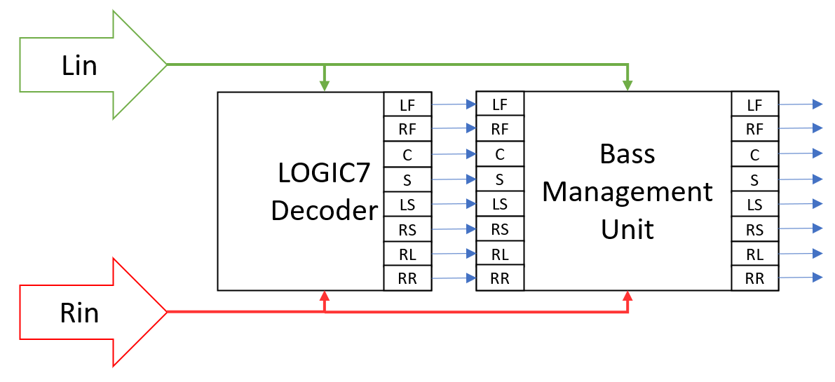
Logic 7 Properties
Below table describes about the Logic7 audio object properties and functionality.

| Properties | Description |
| Display Name | Display the name of the Logic7 audio object in signal flow design. It can be changed based on the intended usage of the object. |
The object has a 2 input channels and 8 output channels. The output channel order is:
- Left Front
- Right Front
- Center
- LFE
- Left Side
- Right Side
- Left Rear
- Right Rear
This object supports all framework configurable sample rates and block lengths.
Mode
There are no mode available for Logic 7 audio object.
Additional Parameters
There are no additional parameters available for Logic 7 audio object.
Tuning Parameters
| Parameter | Description | Unit | Min | Max | Default |
| Matrix Type | Determines the amount of center channel blending across the left and right front channels and the degree of spatial separation between the side and rear channels.
|
None | 0 | 1 | 1 |
| Steering XOver Frequency | Determines cross over frequency of the low pass filter that is used to extract the low pass signals | Hz | 10 | 500 | 200 |
| Side Left / Right Steering Limit | Determines the amount of front left and right signals mixed into the side channels | deg | -45 | 45 | 25 |
| Side Center / Surround Stereo Limit | Determines the amount of center channel signal that is mixed into the side channels | deg | -45 | 45 | 20 |
| Side Center / Surround Mono Limit | Determines the amount of monaural source signals that are mixed into the side channels | deg | -45 | 45 | 20 |
| Rear Center / Surround Mono Limit | Determines the amount of monaural source signals that are mixed into the rear channels | deg | -45 | 45 | 20 |
| Rear Left / Right Steering Limit | Determines the amount of front left and right signals mixed into the rear channels | deg | -45 | 45 | 25 |
| Rear Center / Surround Stereo Limit | Determines the amount of center channel signal that is mixed into the rear channels. | deg | -45 | 45 | 20 |
| Side Shelf Type | Refers to a high frequency shelving filter that is applied to signals steered to the side channels only
|
None | 0 | 2 | 0 |
| Rear Shelf Type | Refers to a high frequency shelving filter that is applied to signals steered to the rear channels only
|
None | 0 | 2 | 0 |
Tuning Panel

Control Parameters
There are no control parameters available for Logic 7 audio object.
Native Panel
Logic 7 audio object does not support native panel.
10.Virtual Venues
Virtual Venues is a fully configurable, state-of-the-art technology to recreate the acoustic impression of a target room, space or concert hall. It consists of multiple processing objects, among them Venue Verb, Auto Balance and Cross Fader. These are the key building blocks and will be described below.
10.1.VenueVerb
VenueVerb is a reverb algorithm based on Lexicon’s “SpiderVerb” and can be considered the core of Virtual Venues. Venue Verb processes input audio signals by applying virtually created acoustical environments. The result is that the perceived acoustical behaviour of the listening environment is changed depending on the acoustical parameters of the virtual rooms which are tuned by VenueVerb.
VenueVerb Properties
Below table describes about object properties and functionality of VenueVerb audio object.
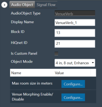
| Properties | Description |
| Display Name | Display the name of the VenuVerb audio object in signal flow design. It can be changed based on the intended usage of the object. |
| Object Mode | CFQLS supports following audio objects
|
Supported Configurations:
- Sample rate = 48 kHz, 96 kHz
- Block lengths = Powers of 2 from 32 to 512 samples (32, 64, 128, 256, 512) and multiples of 48 between 48 and 480 (48, 96, 144, 192, 240, 288, 336, 384, 432 and 480)
Mode
| Mode | Description |
| 4 in, 8 out enhanced mode | This mode uses 4 inputs, which can be used for music and/or microphones and provides 8 uncorrelated outputs. |
| 4 in, 8 out standard mode | This mode uses 4 inputs, which can be used for music and/or microphones and provides 8 uncorrelated outputs. The inputs are downsampled, processing is done with downsampled signal and upsampled to get the final output. |
| 2 in, 2 out enhanced mode | This mode uses 2 inputs, which can be used for music and/or microphones and provides 2 uncorrelated outputs. |
| 2 in, 2 out standard mode | This mode uses 2 inputs, which can be used for music and/or microphones and provides 2 uncorrelated outputs. The inputs are downsampled, processing is done with downsampled signal and upsampled to get the final output. |
| 2 in, 4 out enhanced mode | This mode uses 2 inputs, which can be used for music and/or microphones and provides 4 uncorrelated outputs. |
| 2 in, 4 out standard mode | This mode uses 2 inputs, which can be used for music and/or microphones and provides 4 uncorrelated outputs. The inputs are downsampled, processing is done with downsampled signal and upsampled to get the final output. |
Additional Parameters
| Parameters | Description |
| Max room size in meter | This parameter allows you set room size ranging 8 to 40 m in the signal flow designer tool. A reduction of the maximum room size will decrease the memory that is required for the object. |
| Venue Morphing Enable/Disable | This parameter can enabled or disabled in the signal flow designer tool. Enabling this parameter will add control inputs through which the basic tuning parameters listed below, can be updated. Updating through these control inputs will be done via a mute cycle of the output audio. Venue morphing parameters will be made available only when Venue Morphing is enabled. These control the speed and duration of the mute implementation. |
Tuning Parameters
Basic tuning parameters: The VenueVerb has 14 basic tuning parameters to adjust the overall reverb properties.
| Name | Units | Format | Range | Default |
| MIDRT | – | float | 0.0f – 0.8f | 0.216f |
| RTHICUT | Hz | ULong |
100-12000 (In the case of down-sampled mode max range is half of it) |
5962 |
| ROOMSIZE | m | float | 8.0f-40.0f | 37.0f |
| ALLPASS | – | float | 0.0f-1.0f | 0.8f |
| DIFFUSION | – | float | 0.0f-1.0f | 0.845f |
| PREDELAY | ms | float | 0.0f-200.0f | 0.045f |
| SHAPE | – | float | 0.0f-64.0f | 18.0f |
| SPREAD | percent | float | 0.0f-100.0f | 75.0f |
| MIX | – | float | 0.0f-1.0f | 1.0f |
| WETLOWPASS | Hz | ULong |
100-20000 (In the case of down-sampled mode max range is half of it) |
10000 |
| RATE | – | float | 0.1f-0.7854f | 0.224f |
| WANDER | percent | float | 0.0f-100.0f | 0.0f |
| ECHOTIMEMASTER | – | float | 0.0f-1.0f | 0.114f |
| ECHOLEVELMASTER | – | float | 0.0f-1.0f | 0.091f |
Advanced tuning parameters: It has 32 parameters to individually adjust delays and levels of early reflections for each output channel.
| Name | Units | Format | Range | Default |
| PRIMARYECHODELAY_<N> N=(A,B,C,D) | s | float | 0.0 f – 0.7f | 0.1f |
| PRIMARYECHOLEVEL_<N> N=(A,B,C,D) | – | float | 0.0f – 1.0f | 0.0f |
| SECONDARYECHODELAY_<N> N=(A,B,C,D) | s | float | 0.0 f – 0.7f | 0.1f |
| SECONDARYECHOLEVEL_<N> N=(A,B,C,D) | – | float | 0.0f – 1.0f | 0.0f |
| PRIMARYECHO<N>LEVEL N=(1:8) | – | float | 0.0f – 1.0f | 0.0f |
| SECONDARYECHO<N>LEVEL N=(1:8) | – | float | 0.0f – 1.0f | 0.0f |
Venue Morphing Parameters: Two parameters available only when Venue Morphing is enabled.
| Name | Units | Format | Range | Default |
| MORPHRAMPTIME | ms | float | 5.0 f – 10000.0f | 50.0f |
| MORPHHOLDTIME | ms | float | 5.0 f – 10000.0f | 500.0f |
10.1.1.VenueVerb Panel
Virtual Venues audio objects native panel comprises of following components.
- Venue Verb
- Crossfader
- Autobalance
For detailed working of AOs, please refer to the Virtual Venues object user guide.
Venue Verb
The Venue Verb recreates the acoustic impression of a target room, space or concert hall.
This object processes input audio signals by applying virtual venues (virtually created acoustical environments). The result is that the perceived acoustical behavior of the listening environment is changed depending on acoustical parameters of virtual rooms which are tuned by VenueVerb audio object.
For room size can be set from 8-40 m.
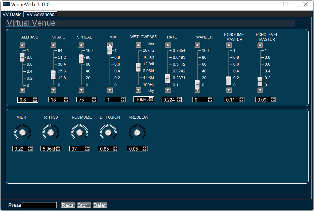
In Advanced tab , Primary Echo delay and Secondary echo delay is used to tune the delays for each output channel. Primary Echo Level and Secondary echo is used to tune the levels of early reflections for each output channel.

Crossfader
Crossfade module allows to add channel pairs with comfortably adjustable levels.
Crossfade is a common type of audio transition between two clips, in which the first clip’s audio fades down while the second clip’s audio simultaneously fades up. Crossfader AO functionality is to mix 4 inputs down to 2 outputs with a linear crossfade applied.
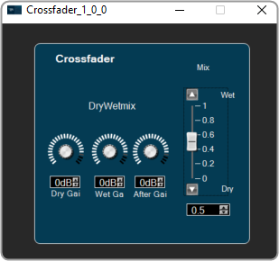
- A crossfader parameter (Mix slider) is provided to easily crossfade between the first and second input channel groups. Range is 0 to 1.
- Dry Gain is to tune gain for the first input channel groups are provided. They are applied in addition to the crossfader, to achieve an offset or to be able to adjust the volume for only one input channel group and leave the other untouched. Range is -120 db to 20 db.
- Wet Gain is to tune gain for the second input channel groups are provided. They are applied in addition to the crossfader, to achieve an offset or to be able to adjust the volume for only one input channel group and leave the other untouched. Range is -120 db to 20 db.
- After gain parameter is adjust additional control of the overall output volume. Range is -120 db to 20 db.
Autobalance
AutoBalance balances limits the levels of up to four microphone inputs. It computes the average of each input and boosts or attenuates it according to the loudness of the other inputs. This is important to avoid loud sounds, e.g., when a microphone is accidentally touched or to make gentle sounds audible.

10.2.AutoBalance
AutoBalance balances limits the levels of up to four microphone inputs. It computes the average of each input and boosts or attenuates it according to the loudness of the other inputs. This is important to avoid loud sounds, e.g., when a microphone is accidentally touched or to make gentle sounds audible.
The module has four inputs and four outputs for the individual microphone channels.
Tuning Parameters
| Name | Unit | Format | Range | Default |
| NUMACTIVEINPUTS | – | ULong | 2 – 4 | 2 |
| MIDRTATTACK | ms | Float | 0.1 – 10 | 2 |
| MIDRTDECAY | ms | Float | 0.1 – 5 | 3.3 |
| AVERAGINGTIMEMS | ms | Float | 1 – 100 | 1 |
| OUTLIERMODE | – | Uint | 0 – 1 | 1 |
| KILLSWITCH | – | Uint | 0 – 1 | 0 |
| BYPASS | – | Uint | 0 – 1 | 0 |
10.2.1.AutoBalance Panel
Autobalance AO supports native panel. The native panel window has different controls for enabling and disabling various modes and for configuring tuning parameters. Native panel can be opened by double-clicking on the Autobalance object in the SFD.

10.3.Crossfader
The Crossfader module allows users to add channel groups with comfortably adjustable levels. It has N = x * 2 inputs (x = 1…M) in the following order:
- 1 in 1 left
- 2 in 1 right
- 3 in 2 left
- 4 in 2 right
And N/2 outputs:
- 1 out left
- 2 out right
Tuning Parameters
- A crossfader parameter (slider) is provided to easily crossfade between the first and second input
channel groups. - Individual gain parameters for the first and second input channel groups are provided. They are applied
in addition to the crossfader, to achieve an offset or to be able to adjust the volume for only one input
channel group and leave the other untouched. - An overall gain parameter is provided to additionally control the overall output volume.
|
Name
|
Unit
|
Format
|
Range
|
Default
|
|
GAIN1
|
dB
|
Float
|
-120 – 20
|
0
|
|
GAIN2
|
dB
|
Float
|
-120 – 20
|
0
|
|
FADERVALUE
|
–
|
Float
|
0 – 1
|
0.5
|
|
MASTER
|
dB
|
Float
|
-120 – 20
|
0
|
10.3.1.Crossfader Panel
CrossFader AO supports native panel. The native panel window has different controls for configuring tuning parameters. Native panel can be opened by double-clicking on the Crossfader object in the SFD.
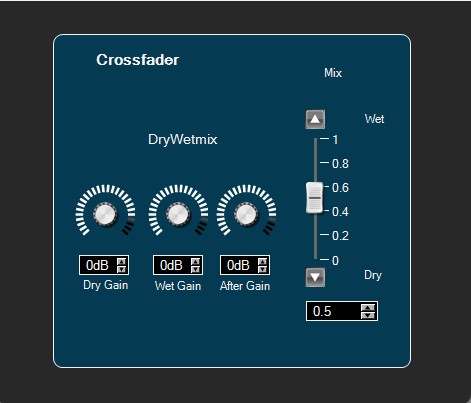
11.Vehicle Noise Control (VNC) Objects
Vehicle Noise Control (VNC) audio objects category contains the following audio objects:
11.1.ALA Control
The purpose of the ALA Control audio object is to calculate the Gain Factor by using control inputs: MNR (Music to Noise Ratio), vehicle speed and entertainment volume. These are the factors used to compute Compander parameters (Compressor Ratio, Threshold, Extra Gain and After Gain) used in the VNC ALA CAO.
The object has no audio inputs and only four control inputs and outputs.
This module uses the following control inputs and outputs:
Tuning Parameters
| Parameter | Min | Max | Default | Description |
| Mode | 0 | 2 | 1 | Mode of operation
|
| VolumeRange | 0.0 | 1.0 | 0.1 | Volume range |
| CompanderThreshold | -140.0 | 0.0 | 0.0 | Compander threshold: The Compressor starts compressing the signal above this level. |
| companderGainZeroDb | -40.0 | 40.0 | 0.0 | Gain for 0dB |
| companderMinBoost | -20.0 | 20.0 | 0.0 | Minimum boost |
| companderMaxBoost | -20.0 | 20.0 | 0.0 | Maximum boost |
| minLvlDelta | 0.0 | 100.0 | 0.0 | Minimum level delta: Threshold for the level jump criteria. If the entertainment or announcement level delta is larger than this threshold, the algorithm is triggered. |
| minTimeDelta | 0.0 | 100.0 | 0.0 | Minimum time delta: Time threshold that keeps the algorithm to be triggered too often. If a big level jump is present, than we ignore this time delta |
Control Inputs:
| Speed | 0.0 | 300.0 | 0.0 | Control for input speed |
| Entertainment Volume | 0.0 | 200.0 | 0.0 | Control for input Entertainment volume. |
| GAL to User | 0.0 | 200.0 | 0.0 | Control input GAL(Speed dependent volume) to User amount. |
| MNR to User | 0.0 | 100.0 | 0.0 | Control input MNR(Music To Noise Ratio) to User amount. |
Control Outputs:
| Compressor Ratio | 0 | 20 | – | Decide how much signal needs to compressor as compare to input. |
| Threshold | -140.0 | 0.0 | 0.0 | Above this level compressor starts to compress. |
| Extra gain | -20.0 | 20.0 | 0.0 | Control Output Extra gain |
| After gain | -20.0 | 20 | 0.0 | Control Output After gain |
Design Time Parameters:
The AlaControl audio object has one additional configuration variable: Block Control. This configuration variable can be configured during design time.

The default value for “Block Control” additional configuration is disabled (0).

When “Block Control” is enabled (1), the control inputs and control outputs are grouped.

11.2.Compander
ALA Compander audio object is the core of complex ALA object. This object is basically a combination of a compressor and expander module. Its aim is to calculate target gain that has to be applied to the input entertainment signals, according to user’s tuning and according to the updated parameters received from ALA Control audio object.
In BYPASS mode the dynamic effect of the ALA is completely bypassed. Here Compander acts as if it is a compressor of ratio 1 and both after gain and extra gain are set to zero. In the case of NO_EXTRA_GAIN mode, the Compressor Ratio and the After Gain are dynamically adjusted based on the parameterization given to the module.
ALA Compander audio object is added with resetObjectHistory API which clears the history data. This API can be called from application to clear the history.
Control Inputs
| Control Input | Min | Max | Default | Unit | Description |
| Compressor Threshold | -140 | 0 | -30 | dB | The threshold level for gain reduction or expansion |
| Compressor Ratio | 1.0 | 20.0 | 1.0 | controls the amount of compression that occurs once the signal rises above the threshold | |
| Compander After Gain | -20.0 | 20.0 | 0.0 | dB | Gain which can be applied to makeup the amount of level (to be recovered) lost during compression |
| Compander Extra Gain | -20.0 | 20.0 | 0.0 | dB | parameter to compensate the level of weak sources |
Tuning Parameters
| Parameter | Min | Max | Default value | Description |
| Threshold | -140 | 0 | -30.0(dB) | Compander threshold: the compressor starts compressing the signal above this level ((This value is just used for Init reasons and will be overwritten by the next controlSet call and will be controlled by AlaControl or any other object connected to the first pin) |
| Ratio | 1 | 20 | 1 | Compression ratio |
| Attack | 1 | 10000 | 20.0(ms) | The time for compander to reach to full compression factor from zero compression |
| Release | 1 | 10000 | 50.0(ms) | Time to stop compression |
| Bypass | 0 | 1 | 0 | Bypass the dynamic effect of ALA object |
| rms_smoothing | 0 | 10000 | 0.0(ms) | Average rms computed from last and previous rms values calculated |
| soft_knee | -20 | 20 | 0.0(dB) | Compressor knee depth (defines the drastic or smooth transition between no compression and compression in given ratio) |
| after_gain | -20 | 20 | 0.0(dB) | The gain after compression |
| peak_hold | 0 | 10000 | 0(ms) | Compressor peak hold time |
| Ngate_treshold | -140 | 0 | -140.0(dB) | Noise gate threshold – Signal below this threshold will be attenuated, no boost will be applied |
| Ngate_attack | 1 | 10000 | 20.0(ms) | Noise gate attack time – time for gate to open |
| Ngate_release | 1 | 10000 | 50.0(ms) | Noise gate release time – time to get the gate closed |
| Ngate_gain_reduction | -50 | 50 | 0.0(dB) | Noise gate gain reduction |
| Ngate_hyst | -50 | 50 | 0.0(dB) | Noise gain hysteresis |
11.3.AlaGain
The AlaGain audio object does apply the gain levels which are calculated by the Compander audio object to its input signals. Its last audio input channel has to be connected to the Compander output. The content of thisconnection is used as a buffer of gain levels (one per sample) which are applied to all other input channels of AlaGain.
Tuning Parameter
AlaGain has only 1 tuning parameter which is used to switch between processing and bypass.
- AlAGain mode Tuning Parameter is set to “0” input is copied to output without any processing,
- AlAGain mode Tuning Parameter is set to “1” it will enabled AlAGain processing,
|
Parameter
|
Unit
|
Format
|
Range
|
Default
|
| AlaGain Mode | none | ULong | 0 – 1 | 0 |
11.4.VNC Control
This module has no audio inputs, only 29 control inputs and seven control outputs. It acts as a translation module for vehicle specific control signals. It requires the following control inputs.
|
|
Tuning Parameters
| Index | Name | Offset [bytes] | Description | Range | Default | Unit |
| 0 | Vnc mode | 0 | Description of the modes in section 6.2.1 | 0 to 255 | 16 (0x00000010) | – |
| 1 | MicAmntClosed | 8 | Gain for microphone on closed roof | 0.0f to 1.0f | 0.0f | – |
| 3 | MicAmntOpen | 12 | Gain for microphone on opened roof | 0.0f to 1.0f | 0.0f | – |
| 3 | MinLvlDelta | 16 | Threshold for the level jump criteria. If the entertainment or announcement level delta is larger than this threshold, the algorithm is triggered | 0.0f to 100.0f | 0.0f | dB |
| 4 | MinTimeDelta | 20 | Time threshold that keeps the algorithm to be triggered too often. If a big level jump is present, than we ignore this time delta. | 0.0f to 100.0f | 0.0f | ms |
| 5 | NoiseDetectOffset | 24 | Noise detection offset | -200.0f to 200.0f | 0.0f | dB |
| 6 | NoiseDetectFactHi | 28 | Noise detection high factor | 0.0f to 1.0f | 0.0f | – |
| 7 | NoiseDetectFactLo | 32 | Noise detection low factor | 0.0f to 1.0f | 0.0f | – |
| 8 | FastAdaptAccelThresh | 36 | This factor dictates the temporary fast adaption of the algorithm. For example, if the car breaks too quickly, we might need to use the fast timing constants for the next vnc_fast_adaption_counter_seed algorithm iterations, unless HU forces us to use other values. | 0.0f to 100.0f | 0.0f | – |
| 9 | FastAdaptCntSeed | 40 | A fast adapt counter seed | 0 to 100 | 5 | – |
| 10 | TimeConstSlow | 44 | A time factor for slow updates on static coefficients | 0.01f to 5.0f | 0.01f | s |
| 11 | TimeConstFast | 48 | A time factor for fast updates on static coefficients | 0.01f to 5.0f | 0.01f | s |
| 12 | TimeAdaptSlow | 52 | A time factor for slow updates on adaptive coefficients | 0.01f to 5.0f | 0.01f | s |
| 13 | TimeAdaptFast | 56 | A time factor for fast updates on adaptive coefficients | 0.01f to 5.0f | 0.01f | s |
Design Time Parameters
The VncControl audio object has one additional configuration variable: Block Control. This can be configured during design time so as to enable or disable Block Control feature. The default value for “Block Control” additional configuration is disabled (0).
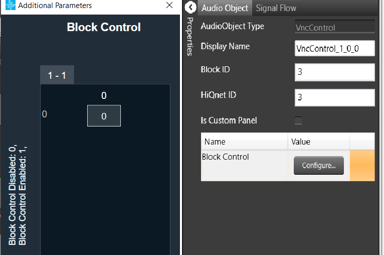
When Block Control is enabled(1), 6 speed dependent control inputs are grouped.

When disabled, control inputs are not grouped.

11.5.NoiseEst
The purpose of the noise estimation module is to estimate the level of noise in the vehicle coming from the engine, the road, and other error sources while music is playing. Inputs given to the module are the digital output sound data in its final stage before it is sent to the DACs, and the feedback coming from a microphone mounted somewhere in the vehicle cabin. When users know what is sent to each loudspeaker, they can correlate that information with the microphone input to get a channel estimate.
This is only a component of the complete VNC implementation.
The coefficients get dynamically calculated and updated. This approach has the benefit of being able to adapt to changing circumstances. For example, if a window is opened while driving, the noise increases. In addition to increased noise, the optimal channel estimate changes as well.
Control Parameters
- Door slam count: Number of frames exceeding the threshold. (This count is to be used to detect door slams.)
- Err smallest RMS: Small error threshold.
- Err median RMS: Error estimation after median filtering.
- Audio channels: Audio channel range varies from 2 to 7.
Tuning Parameters
| Parameter | Min | Max | Default | Description |
| Error Decay Time | 0.0 | 10.0 | 0.05 | Error decay time is measured in milliseconds. |
| Mic Gain | -20.0 | 20.0 | 0.0 | Microphone gain measured in dB. |
| Stepsize | 0.0 | 5.0 | 0.03 | NLMS step size. |
| Powersum Min | 0.0 | 1000.0 | 0.003 | Minimum power value, NLMS parameter. Lower bound for input signal when calculating NLMS step size. |
| Doorslam Threshold | 0.0 | 1000.0 | 1.2 | Upper bound for door slam detection |
| Power Threshold | 0.0 | 1000.0 | 0.003 | Threshold for which input power leads to coefficients update |
| Doorslam Timeout | 0.0 | 10.0 | 0.0 | Door slam detection timeout |
| Readapt Timeout | 0.0 | 10.0 | 0.0 | Open window enforce re-adaptation timeout |
| Tuning channel | 1 | (Num of channels -1) | 1 | Selection of channel for which the adaptive coefficients get copied over to the static coefficients on enabling tuning (see “Tuning enabled”) |
| Tuning enabled | 0 | 1 | 0 | Enable copying the adaptive filter coefficients of the selected channel (see “Tuning channel”) to the corresponding static filter coefficients |
FIR coefficients
The FIR coefficients for the static and adaptive filters are arranged as follows.
The number of static and adaptive filter coefficient arrays depends on the number of entertainment channels (number of audio input channels – 1). For each entertainment channel there is a static and an adaptive filter coefficient set.
Table shows the case of one entertainment channel, which means there is one FIR static coefficients array and one FIR adaptive coefficients array. If the number of entertainment channels is higher, then first the arrays of FIR static coefficients are allocated then the arrays of FIR adaptive coefficients.
| Parameter | Offset | Range | Default value |
| FIR static 1 coefficients | 40 | -9999.0 – 9999.0 | 0.0 |
| FIR static 2 coefficients | 1064 | -9999.0 – 9999.0 | 0.0 |
| FIR adaptive 1 coefficients | 2088 | -9999.0 – 9999.0 | 0.0 |
| FIR adaptive 2 coefficients | 3112 | -9999.0 – 9999.0 | 0.0 |
Each FIR coefficient array stores the filter coefficients in reverse order compared to the common understanding of FIR coefficients, meaning the last value in the array of one filter set is the first coefficient of the FIR filter.
11.5.1.NoiseEst Custom Panel
This panel contains tuning parameters for the noise estimator, which processes the mic signal and produces noise-related information for the VNC object.

12.TPS
The aim of the Tracking Power Supply (TPS) Audio Object is to provide PWM duty cycle values to boosted power supply controller ICs, as well as providing a reference to adjust TPS output on extension amplifiers or micro- controllers managing discrete amplifiers. This results in changing the power amplifier supply voltage in accordance to the levels of the audio output signals. Adaptive supply voltage allows to increase the efficiency and decrease electromagnetic noise generated by the amplifiers.
Design Time Parameters
- AMPFACTOR – Amplification factor. Describes mapping of float numbers into output voltage.
- TPSSHIFT – Shift parameter for TPS voltage. This value must be evaluated from the amplifier’s hardware specifications.
- TPSFACTOR – Scale factor parameter for TPS voltage. This must be evaluated from the amplifier’s hardware specifications.
- MINTPSVOLTAGE – Minimum TPS voltage MAXTPSVOLTAGE – Maximum TPS voltage.
Tuning Parameters
|
Name
|
Unit
|
Format
|
Range
|
Default
|
Description |
| Audio Delay | ms | Float | 0 | 0 | Delay Buffer length |
| TPS Delay | – | Float | 0 – 2048 | 0 | Delay of TPS signal |
| Hold Time | ms | Float | 0 – 10000 | 1000 | TPS voltage hold time |
| Hold Intervals | – | Float | 0 – 2048 | 32 | Number of stored TPS values in Detection buffer |
| Voltage Headroom | V | Float | 0 – 10 | 5 | Headroom added to the envelope for TPS voltage |
| Ramping Up Time | ms | Float | 0 – 2000 | 0 | Ramping time for raising TPS voltage (for full-scale TPS change) |
| Ramping Down Time | ms | Float | 0 – 2000 | 0 | Ramping time for falling TPS voltage (for full-scale TPS change) |
| ScalingMode | – | Float | 0 – 1 | 1 | Enables scaling mode |
| CompFilter | – | Float | 0 – 1 | 0 | Enables compensation Filter |
| B0 coeff | – | Float | -1E+10 – 1E+10 | 0 | Compensating filter’s b0 coefficient |
| B1 coeff | – | Float | -1E+10 – 1E+10 | 0 | Compensating filter’s b1 coefficient |
| B2 coeff | – | Float | -1E+10 – 1E+10 | 0 | Compensating filter’s b2 coefficient |
| A1 coeff | – | Float | -1E+10 – 1E+10 | 0 | Compensating filter’s a1 coefficient |
| A2 coeff | – | Float | -1E+10 – 1E+10 | 0 | Compensating filter’s a2 coefficient |
The parameters must match the hardware specification and the integration will be different among platforms. Please refer to the appropriate platform integration guide and specifications.
13.Power Manager
The aim of Power Manager is to protect speakers from damage. The object consists of three limiters grouped into two main sub-blocks. The peak-voltage sub-block consists of a frequency-dependent limiter which protects against cone over-excursion. The power-limiter sub-block is made up of a short-term and a long-term limiter, each of which can be configured to attack at a distinct power threshold over an independent time-averaging window.
The power limiter is meant to protect the speaker’s components from overheating. The Power Manager AO has the following additional parameters:
Design Time Parameters
Look-ahead delay [samples]: The fixed delay in samples for the audio signal. This delay improves the response of the peak-voltage limiter at frequencies over 10 kHz.
Tuning Parameters
Power manager exposes below parameters as tuning parameters in GTT for each channel:
|
Name
|
Unit
|
Format
|
Range
|
Default
|
Description |
| Short-term Average Time | s | Float | 0.1 – 100 | 2 | Averaging time-window for the short-term power limiter. |
| Long-term Average Time | s | Float | 0.1 – 100 | 10 | Averaging time-window for the long-term power limiter. |
| Short-term Power Threshold | W | Float | 0 – 100 | 10 | The power threshold over which the short-term power limiter will start reducing gain. |
| Long-term Power Threshold | W | Float | 0 – 100 | 5 | The power threshold over which the long-term power limiter will start reducing gain. |
| Power Attack Rate | s | Float | 0 – 5 | 1 | The rate at which any of the power limiters will reduce gain when the threshold is crossed. |
| Power Release Rate | s | Float | 0 – 5 | 1 | The rate at which any of the power limiters will go back to unity gain when the threshold is not being crossed. |
| Power Depth | – | Float | 0 – 1 | 3.8E-07 | The maximum attenuation allowed for the power limiters. |
| Voltage-Peak Time-Constant | s | Float | 0 – 5 | 0.008 | The tau-constant for the first-order averaging filter used in envelope detection. The envelope level will decay at this rate when the signal-peak is at a lower level. |
| Voltage Threshold Linear Scale | V | Float | 0 – 100 | 1 | The reference threshold from which the contour filters bias the incoming signal. |
| Voltage Attack Rate | s | Float | 0 – 30000 | 2000 | The rate at which the peak-limiter reduces gain when the contoured threshold has been crossed. |
| Voltage Release Rate | s | Float | 0 – 30000 | 500 | The rate at which the peak-limiter goes back to unity gain when the contoured threshold is not being crossed. |
| Voltage Scalar | V | Float | 1 – 100 | 1 | The relation between the configured limiter-threshold voltage and the output voltage of the power IC used. |
In Addition to above tuning parameter Power manger uses below filters to model Peak-voltage and admittance of speaker
Contour Filters: Cascade of three bi-quadratic filters which are used to model the frequency-dependent peak-voltage limit for the speaker.
Admittance Filters: Cascade of three bi-quadratic filters which are used to model the admittance of the speaker. These are used to calculate current consumption and in turn estimate power.
Contour filters and Admittance filters coefficients loaded into DSP/Amplifier can be visualized in SV tree and GTT panel.
|
Name
|
Unit
|
Format
|
Range
|
Default
|
| b0 | – | Float | -100 – 100 | 1 |
| b1 | – | Float | -100 – 100 | 0 |
| b2 | – | Float | -100 – 100 | 0 |
| a1 | – | Float | -100 – 100 | 0 |
| a2 | – | Float | -100 – 100 | 0 |
GTT panel also displays frequency response of filters. Please note that the filter coefficients cannot be tuned from GTT. The filter coefficients are loaded in DSP/Amplifier through a unique API.
Native Panel
PowerManager AO supports native panel. The native panel window has different controls for configuring tuning parameters, fields for displaying coefficients and graph for displaying output voltage/ power. Native panel can be opened by double-clicking on the PowerManager object in the SFD.

13.1.Power Manager Panel
This panel is used to display voltage contour, admittance filter coefficients loaded in device. Tuning of power and voltage limiting for each channel can be performed using this panel.
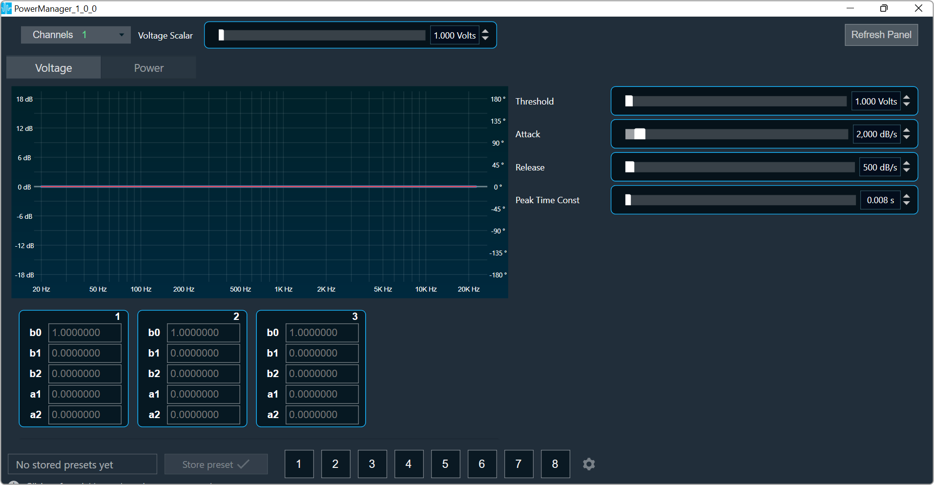
Channel List
On the top left of the PowerManager, there is a list from which you can choose a channel for the current core. The current channel is marked with a green square and its details are displayed in the header of the channel list.

Tab selection
You can select Voltage or Power tab to view their specific chart and tuning parameters.
The Voltage tab is selected by default.

Refresh Panel
Refresh panel option is used to update coefficient filters data without relaunching panel.

Coefficient Chart
The panel has a chart that has only total amplitude and total phase graphs.
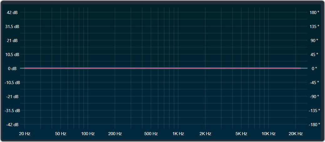
Contour Filter 1-3
Three separate bi-quadratic filters are used to model the frequency-dependent peak-voltage limit for the speaker.

Admittance Filter 1-3
Three separate bi-quadratic filters which are used to model the admittance of the speaker. These are used to calculate current consumption and in turn estimate power.

Tuning Parameters
Voltage limiting parameters
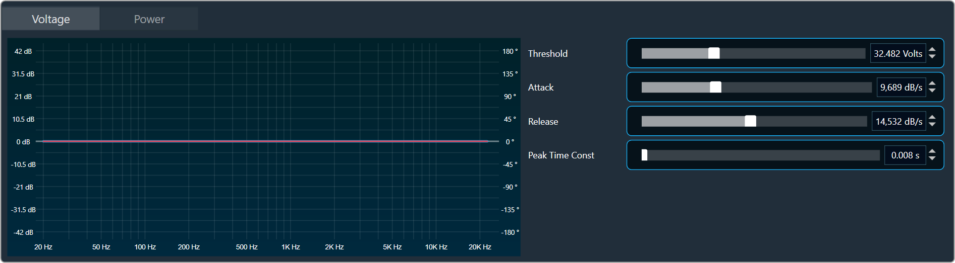
- Voltage Threshold Linear Scale: The reference threshold from which the contour filters bias the incoming signal.
- Voltage Attack Rate: The rate at which the peak-limiter reduces gain when the contoured threshold has been crossed.
- Voltage Release Rate: The rate at which the peak-limiter goes back to unity gain when the contoured threshold is not being crossed.
- Voltage-Peak Time-Constant: The tau-constant for the first-order averaging filter used in envelope detection. The envelope level will decay at this rate when the signal-peak is at a lower level.
Power limiting parameters

- Short-term Power Threshold: The power threshold over which the short-term power limiter will start reducing gain.
- Short-term Average Time: Averaging time-window for the short-term power limiter.
- Long-term Power Threshold: The power threshold over which the long-term power limiter will start reducing gain.
- Long-term Average Time: Averaging time-window for the long-term power limiter.
- Power Attack Rate: The rate at which any of the power limiters will reduce gain when the threshold is crossed.
- Power Release Rate: The rate at which any of the power limiters will go back to unity gain when the threshold is not being crossed.
- Power Depth: The maximum attenuation allowed for the power limiters.
Changing the parameter value
You can change the value in four ways:
- Using slider button: Select the slider to adjust the value.
- Using mouse scroll: Click on the respective column and use mouse scroll to adjust the value.
- Chaning the value in the text box: Select the respective column and enter the value within the specified minimum and maximum range. Once you’ve entered the value, press Enter, and the slider will automatically adjust based on the input.
- Using the increase and decrease buttons
 you can change delay by calculated.
Maximum/Minimum parameter value
Maximum and minimum parameter values are derived from corresponding state variable of power manager.
14.Voice Objects
- SSE – Speech Signal Enhancement (Cerence 3rd party)
- ICC – In car communication (Cerence 3rd party)
14.1.SSE
The SSE (Speech Signal Enhancement) is a 3rd party product by Cerence™.
The SSE is an advanced, modular library of field-proven algorithms specifically designed to improve the quality of voice communication. It enhances the performance of in-car hands-free communication and speech recognition systems. The library contains algorithms like beamforming, echo cancellation, noise reduction, wind noise removal, automatic gain control, bandwidth extension etc. (For more details see the SSE product specification.)
The library supports a large variety of configurations – from a simple single channel system to a multi-channel solution with many additional features. By means of SCD (SSE Configuration Data) the algorithms can be adjusted to the system and the acoustic environment they are used in. SSE gets a various number of microphone signals representing audio captured by microphones in the car cabin, by the IoT device or similar. For hands-free applications it may also get a receive input signal representing the signal from the far-end speaker. The optional reference signals are used by the echo canceller in hands-free applications and speech recognition with barge-in.
14.2.ICC
The ICC (In Car Communication) is a 3rd party product by Cerence™.
The communication between passengers in a vehicle – especially between front and rear passengers – is often difficult due to the high acoustic loss of the speech level and the background noise superimposing the speech signal. Therefore, speakers must speak louder than normal, which makes longer conversations stressful, and if the driver turns his head even driving safety is impaired. The In-Car Communication audio object helps to overcome these problems by improving the intelligibility of conversations between front and rear passengers in a vehicle. The ICC system picks up the speech signal of the seat dedicated microphones and distributes them via the sound system. Signals from the front passengers are played back via the rear loudspeakers; signals from the rear speakers via the front loudspeakers.
The signal processing algorithms of the ICC attenuate background noise and ensure stable operation of the system by suppressing feedback echoes and howling. This is accomplished by noise and feedback suppression algorithms optimized for the low latency requirements of the ICC system. An automatic gain control compensates for varying speech levels of different speakers, while an adaptive level control adjusts the system gain to the current background noise level. This ensures an unobtrusive operation of the system while providing always the required speech gain. The user can select between different gain curves to adjust the ICC system to his needs. The overall system gain is limited to guarantee system stability and the system is automatically deactivated if the entertainment level exceeds a predefined level using an entertainment reference channel. Distortion of the audio signal at high playback levels may be avoided.
15.FFT Based Processing
- FFTCalc
15.1.FFTCalc
The FFTCalc AO is used to get frequency content based on band energies.
Input block of length L along with previous N-L samples form a frame of length N (number of FFT points). This frame is multiplied with window function and fed to Real Radix 2 FFT. The minimum and maximum FFT point supported is 32 and 4096 respectively. Thus, the minimum and maximum resolution for the sampling rate of 48000 is 1500Hz and 11.72Hz respectively.
The FFTCalc provides 4 fixed control outputs giving band information. Three are for band-specific info and one for the entire spectrum.
Design Time Parameters
- FFT size: an additional configuration parameter, should be selected to be power of 2. Other values are not accepted by GTT.
- FFT size is lower bounded by the block length.
- Block Length: supports all the block lengths supported by the framework upto 4096.
The number of FFT points (N) and sampling rate decides the frequency resolution of the bin. When FFT points selected is lower the frequency bins may not correctly correspond to the designated band and they may fall into adjacent bands because of lower frequency resolution. It is required to correctly choose the number of FFT points. Frequency resolution is computed using the below formula
Frequency resolution = sampling rate/number of FFT points
We recommend choosing FFT points based on frequency resolution requirements.
For E.g if the sampling rate is 48KHz and we want a frequency resolution less than 100Hz Number of FFT points selected can be greater than or equal to 512
- It is recommended to choose either Hamming/Hanning window for better frequency response.
- Currently, the FFTCalc object supports mono channel only
The AO supports in-place computation based on the core type.
Tuning Parameters
| Name | Description | Data Type | Default value | Range | Units |
| Band1LoFrequency | Band 1 Low Band Frequency in Hz | Float | 80 | [0,fmax] | Hz |
| Band1HiFrequency | Band 1 High Band Frequency in Hz | Float | 300 | [0,fmax] | Hz |
| Band2LoFrequency | Band 2 Low Band Frequency in Hz | Float | 600 | [0,fmax] | Hz |
| Band2HiFrequency | Band 2 High Band Frequency in Hz | Float | 2500 | [0,fmax] | Hz |
| Band3LoFrequency | Band 3 Low Band Frequency in Hz | Float | 7000 | [0,fmax] | Hz |
| Band3HiFrequency | Band 3 High Band Frequency in Hz | Float | 15000 | [0,fmax] | Hz |
| WindowFunction |
0-Rectangular Window 1-Hamming Window 2-Hanning Window |
ULong | 0 (Rectangular Window) | [0,2] | NA |
| Mode | FFTCalc mode (No processing/Energy/Power) # | ULong | 0(No processing) | [0,2] | NA |
16.Immersive Audio
Immersive audio objects category contains the following audio objects:
16.1.Mono Detection
The purpose of the Mono Detection audio object is to identify whether the time domain input signal is mono or stereo.
The signal used for the analysis is the 2-channel audio input.
- Control output signal 1 indicates that the input is identified as mono
- Control output signal 0 indicates that the input is identified as stereo
The algorithm consists of Pearson Correlation Coefficient calculation and logic combined with the energy difference between two channels to segregate mono or stereo.
Features
- Available in the Immersive Audio section of GTT
- Supports all framework configurable sample rates and block lengths.
- Supports both Win64 and GUL platforms.
Use Case: This audio object used to define separate audio processing paths depending on their nature.
Supported Configurations:
- Block Length: 128 and 256 samples
- Sample Rate: 24000, 48000 and 96000 Hz
Mono Detection Properties
Below table describes about the Mono Detection audio object properties and functionality.

| Properties | Description |
| # of Audio In | The number of input channels is fixed to two (L-R) and no output channels. |
| Display Name | Display name of the MonoDetect audio object in signal flow design. It can be changed based on the intended usage of the object. |
Mode
Mono Detection audio object doesn’t support any mode.
Additional Parameters
Mono Detection audio object doesn’t have any additional parameters.
Tuning Parameters
| Parameter | Description | Memory Offset | Unit | Default | Range |
| BYPASS | Defines if the MonoDetect bypasses its processing.
|
0 | None | 0 | 0 to 1 |
| THRESHOLD_HI | Defines the upper bound for the region to consider if a signal passes from STEREO to MONO. | 4 | None | 0.995 | 0 to 1 |
| THRESHOLD_LO | Defines the lower bound for the region to consider if a signal passes from MONO to STEREO. | 8 | None | 0.65 | 0 to 1 |
| XDBDIFF | Defines the minimum difference in dBs between the energy of L-R channels to define if a signal is MONO or STEREO. | 12 | None | 0.1 | 0 to 1 |
| TIMETODETECTMONO | Defines the time ramp for transitioning from STEREO to MONO. | 16 | ms | 350 | 0 to 1000 |
| TIMETODETECTSTEREO | Defines the time ramp for transitioning from MONO to STEREO. | 20 | ms | 350 | 0 to 1000 |
| MINXCORR | Defines the maximum correlation value minimum cross-correlation value for a block to be eligible for processing. | 24 | None | 0.5 | 0 to 1 |
| NOISEFLOOR | Defines the minimum mean energy per block accepted by the AO. Energies per block below this threshold will be considered as noise. | 28 | dBs | -30 | -128 to 0 |
Control Parameters
|
Name
|
Description
|
Range
|
Default
|
|
Mono State
|
Mono or Stereo
|
0 – Stereo 1 – Mono |
0
|
Native Panel
Mono Detection audio object does not support native panel.
16.2.NSP Center Extraction
The purpose of the NSP Center Extraction is to estimate the similar content in from two audio input signals (Left and Right) and provide an output with the estimated center channel.
The NspCenterExtraction (Natural Surround Processing Center Extraction) audio object receives a two-channel signal (Left and Right, L and R) and produces five output signals.
- 1 – Center (C)
- 2 – Residual L (L minus C)
- 3 – Residual R (R minus C)
- 4 – Delayed Left (L)
- 5 – Delayed Right (R)
An example of a signal flow design.
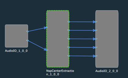
The first output signal is the estimated C channel.
Features
- Available in the Immersive Audio section of GTT
- Supports sample rates: 11025, 12000, 22050, 24000, 44100, 48000 and 96000 Hz
- Supports block lengths: 32, 64, 128 and 256.
- Supports both Win64 and GUL platforms.
NSP Center Extraction Properties

| Properties | Description |
| Display Name | Display name of the NSP Center Extraction audio object in signal flow design. It can be changed based on the intended usage of the object. |
Input and Output: The number of input channels is fixed to 2 and the number of output channels is fixed to 5.
Mode
The audio object doesn’t support any mode.
Additional Parameters
The audio object doesn’t have any additional parameters.
Tuning Parameters
The audio object doesn’t have any tuning parameters.
Control Parameters
The audio object doesn’t have any control parameters.
Native Panel
NSP Center Extraction audio object does not support native panel.
16.3.Decorrelation
The purpose of Decorrelation audio object is to minimize spectral distortion while simultaneously reducing the correlation between the output channels. Different approaches can be applied to the signals to produce different uncorrelated audio channels. The simplest decorrelation approach is to randomize the phase.
In the context of multichannel sound production, decorrelation refers to the process by which one audio input is turned into several output signals with waveforms that appear distinct but sound the same as the source. This method extends the spatial image while avoiding unwanted comb-filtering artifacts.
A computationally efficient approach based on sparse convolution has been devised . This approach uses OVN (Optimized Velvet Noise) filters to achieve decorrelation, and this is the approach being used in the implementation of the Decorrelation AO.
Feature
- Available in the Immersive Audio section of GTT
- Supports sample rates: 11025, 12000, 16000, 22050, 24000, 32000, 44100, 48000, 64000, 96000 Hz.
- Supports block lengths: 4, 8, 16, 32, 64, 128, 256, 512, 1024, 2048, 4096.
- Supports non-zero elements (to store position and amplitude values): 1 to 64.
- Supports both Win64 and GUL platforms.
Decorrelation Properties
Below table describes about the Decorrelation audio object properties and functionality.
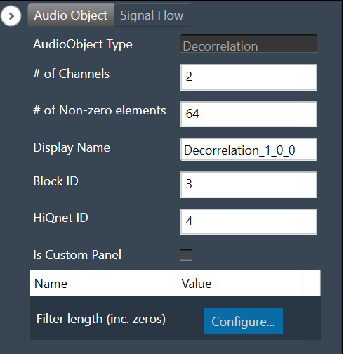
| Properties | Descriptions |
| Number of Channels | Decorrelation audio object supports configurable number of input channels.
The Decorrelation audio object supports the same number of output channels as the number of input channels. |
| Number of non-zero elements | The Decorrelation audio object supports the number of non zero elements, to store position and gain values, ranging from 1 to 64 and 1 being the default.. |
|
Display Name
|
Display name of the Decorrelation audio object in signal flow design. It can be changed based on the intended usage of the object.
|
Mode
The Decorrelation audio object doesn’t support any mode.
Additional Parameters
|
Name
|
Description
|
Range
|
Default
|
|
Filter Length
|
Filter length including zeros and non zero elements.
|
64 to 2048 |
1024
|
Tuning Parameters
| Parameter | Description | Format | Memory Offset | Unit | Default | Range |
| BYPASS | Bypasses the Decorrelation audio object when active.
|
Float | 0 | – | 0 | 0 to 1 |
| COLOR_SPACE_RATIO | Defines the percentage of the maximum decorrelation that the IRs can achieve applied in the current decorrelation process.
|
Float | 4 | – | 100 | 0 to 100 |
| Coefficients for Channel 0 | Coefficients for channel 0 | Float | – | – | – | – |
| Coefficients for Channel N – 1 | Coefficients for channel N – 1 | Float | – | – | – | – |
Control Parameters
There are no control parameters available for Decorrelation audio object.
16.3.1.Decorrelation Panel
The Decorrelation audio panel allows to load the impulse responses (IRs) coefficients to be used for decorrelation processing for each channel. Use “Import” or “Import All” option to import the IRs. The panel will display channel wise graph for coefficients and filter length.

- Channels: Show all channels list, you can select channel to view its graph.
- Sample Rate: Show sample rate of current framework instance.
- Non-zero Taps: Show non-zero elements defined for decorrelation audio object.
- Graph: Show graph of coefficients and filter length.
- Import: Use to import selected channel coefficients file.
- Import All: Use to import all channels coefficients file.
- Send: Use to send non-zero coefficients to device.
Validation
It will validate coefficients file and ask confirmation for below error messages.
- The filter length does not match the number of coefficient rows in the CSV file.
- The number of non-zero elements does not match the number of coefficient rows in the CSV file.
- The CSV file contains more coefficient columns (for Import).
- The CSV file columns do not match the channels (for Import all).
If you click on “Yes”, then it will proceed for import else it will cancel it.
“Import” and “Import All” will update state variables and send non-zero coefficients to device if device online.
16.4.Reverb Lite
The Reverb Lite is a reverb algorithm that processes input audio signals by applying artificial reverberation to a dry signal.
Features
- Available in the Immersive Audio section of GTT.
- Supports sample rates: 22.050, 24, 44.1, 48, 88.2, 96, 176.4, 192, 352.8, 384 kHz.
- Supports block lengths from 16 to 4096 in multiples of 16.
- Supports both Win64 and GUL platforms.
Use Case: This audio object can be used whenever you need to apply reverb to a dry signal. It aims to have a low footprint on MIPS as it is an algorithmic reverb instead of performing convolutions with room impulse responses. In the context of immersive audio, one can use it to generate ambience reverb, which needs to be decorrelated if mixed into further channels.
Reverb Lite Properties
Below table describes about the Reverb Lite audio object properties and functionality.
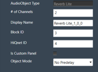
| Properties | Descriptions |
| # of Channels | Enter the number of channels. The number of audio channels it can process is configurable in the SFD.
It supports mono and stereo inputs and the same number of output channels as the number of input channels. |
| Display Name | Display name of the Reverb Lite audio object in signal flow design. It can be changed based on the intended usage of the object. |
This audio object takes the mono/stereo signal as an input and generates reverb from it. The output consists of either the reverb alone (“wet-only”) or a mix between the generated reverb and the original signal. The user can adjust the following parameters:
- Reverb gain, from 0.0 to 1.0
- Reverb time, from 0.0 to 1.0
- Low-pass factor, from 0.0 to 1.0
- High-pass factor, from 0.0 to 1.0
- Pre-delay from 0ms to 500ms (if pre-delay is enabled)
Mode
These are the available modes for the Reverb Lite AO
| Index | Mode | Description |
| 0 | Pre-delay 500ms | Maximum pre-delay of 500ms |
| 1 | Pre-delay Disabled | No pre-delay available. Used to reduce the memory footprint needed by the pre-delay block. |
Additional Parameters
The audio object does not support any additional parameters.
Tuning Parameters
| Parameter | Description | Data Format |
Memory Offset |
Unit | Default Value |
Range |
| Time | Affects feedback damping and output mixing so that a small RT factor resembles a small room, and a large factor approaches infinite reverb time. | float | 0 | None | 0.618 | 0.0 to 1.0 |
| Gain | Linear reverb gain. A value of 0 means no reverb is applied, whereas the maximum gain of 1 applies the maximum amount of reverb in a way that it doesn’t exceed the original signal’s amplitude. | float | 4 | None | 0.25 | 0.0 to 1.0 |
| Lowpass | Internally, three filters are controlled by this, two of them in a feedback path (LP1 and LP2) and PRELP before the feedback path, which affects the reverb bandwidth directly. First order filters are used as they perform well in feedback paths, because they are guaranteed not to exhibit any resonance and offer finer control for soft fadeout of high/low frequencies. | float | 8 | None | 0.75 | 0.0 to 1.0 |
| Highpass | Internally, two first order filters are controlled by this. HP1 as a reverb bandwidth control and HP2 that acts to filter the dampened signal inside the tank circuit. | float | 12 | None | 0.0 | 0.0 to 1.0 |
| Wet only | When set to true, only the generated reverb is present at the output. If false, the input signal is mixed into the output. | ULong | 14 | None | 0 (false) |
0 (false) to 1 (true) |
| Pre-delay | Sets the amount of pre-delay to be applied. Only acts the pre-delay submodule is enabled (Pre-delay 500ms mode) | float | 16 | ms | 0 | 0.0 to 500 |
Control Parameters
There are no control parameters available for Reverb Lite audio object.
Native Panel
Reverb Lite audio object. does not support native panel.
17.Core Objects
The core objects that were retrieved from the xAF dll. The objects that can be used within the core to create the device signal flow are called core objects. Each core object has its own purpose and solves parametric issues which block routing within the core.
Core Objects are classes that are part of the Audio Core (virtual core) class and operate at a higher level than audio objects. The audio processing class itself is a core object. The relationship between core objects and Audio core is similar to that of audio objects and the Audio Processing class.
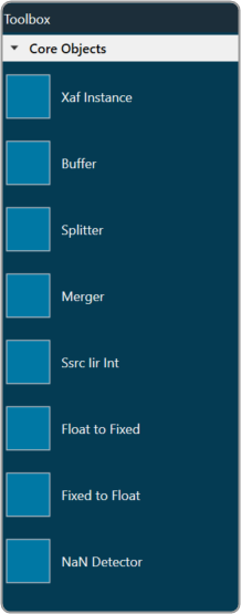
The execution order (or index) of the core object is displayed by Core Object Id. Routing determines the order in which core objects are executed within a core. The core objects that are connected to the core input will be executed first, and the core objects that are connected to the root object after that will be given the next execution order.
The device identification feature is enabled for audio libraries version 13 and higher.
17.1.Xaf Instance
The Xaf Instance is the core object inside which the signal flow for that instance can be created.

- Core Object Id (execution order of core-object with-in core) and Instance Id (index of xAF instance with-in core, based on execution order) will be displayed as read-only fields.
- The sample rate and block length of the instance will control signal flow within the instance. You can change the sample rate and block length of the instance in the properties section.
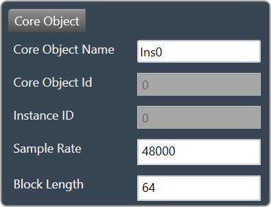
Further information on signal flow creation is available in the GTT Signal Flow Designer guide.
17.2.Buffer
Buffer core object is used to convert the input block length into the required output block length. The buffer core object has an equal number of input and output channels. It can be used as a pass through core object OR it can be used to, as its name suggests, buffer samples from the input to the output. The object does not change the sample rate (it is the same at the input and the output).

If you want to connect two core objects with different block lengths, you can use a buffer core object. As a result, the input block length will be the Block Length of the first core object, and the output block length should be the Block Length of the other core object.

It can be configured as follows:
- If the input block length is equal to the output block length, then it behaves as a pass through object (so you could have an audio core with a buffer object to connect the core input to the output)
- Input and output block lengths must be integer multiple of each other
- When input and output block lengths are not equal, the object handles taking in input at a lower block length and outputting it at a higher one and vice versa. For example, it facilitates the connection of an object at block length 32 to an object at block length 64
Introducing this object into your signal flow for any case but pass through WILL result in latency at the output.
17.3.Splitter
Splitter core object is used to convert one input to multiple outputs of the same sample rate and block length.

- This core object always has a single input.
- In order to make routing from any core object to the splitter both the source core object and splitter core objects sample rate and block length should match.
- Number of output channels for the splitter is configurable.

It is not to be confused with the Splitter audio object.
This object operates in parallel to an xAF instance NOT within it.
17.4.Merger
Merger core object is used to merge multiple inputs into a single output of the same block length and sample rate.

- This core object always has a single output.
- In order to make routing from any core object to merger both the source core object and merger core objects sample rate and block length should match.
- Number of input channels for the merger is configurable.

It is not to be confused with the Merger audio object.
This object operates in parallel to an xAF instance NOT within it.
17.5.Ssrc lir Int
Synchronous Sample Rate Converter (SSRCs) is used to convert the input sample rate to the required output sample rate.
SSRCs are core objects that can operate within an audio core. Currently there is one implementation of SRCs in Awx.

Two options are provided to convert the sample rate. Both these options are mutually exclusive.
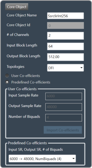
IIR Integer Multiple SSRC
This core object implements a synchronous sample rate converter whose input sample rate / input block length and output sample rate / output block length are integer multiple of each others. This is also an infinite impulse response implementation (IIR).
The object operates in one of 2 modes:
- User Coefficients mode
- Predefined Coefficients mode
Before we get into the details, there are some common configuration parameters between the two.
- The input block length needs to be set by the user.
- The Biquad filter topology. Currently 2 topologies are exposed.
- Direct Form I
- Direct Form II
User Coefficients mode: In this mode, the user has to provide the input and output sample rate. Input and output sample rates should not be equal. The Number of Biquads field is read-only.
User has to import the coefficients by clicking on the button “Import Co-efficients”. Based on the number of coefficients in the file, the Number of Biquads is updated.
Validations for User Coefficients mode: The Input and Output sample rates cannot be the same. Validation is shown when the same values are entered.
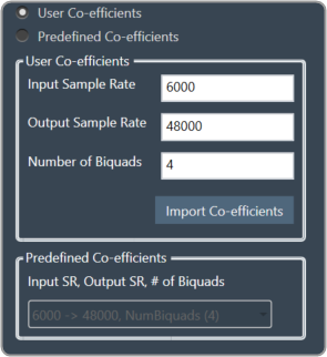
After adding a new “Ssrc lir Int” object and selecting “User Coefficients Mode”, if the coefficients are not imported, the following message will be displayed on various operations such as “Save”, “Edit Device”, “Copy Core Objects” and “Paste Core Objects”. After importing coefficients, the user can perform the required operation.

Predefined Coefficients mode: In this mode, the xAF dll is used to read the input sample rate, output sample rate, and the number of biquads. When a value in the combo box is selected, the xAF dll is also used to fetch the corresponding coefficients.
Biquad Co-efficient has to be re-imported whenever the mode is switched between Predefined Co- efficient mode to User Co-efficient mode.
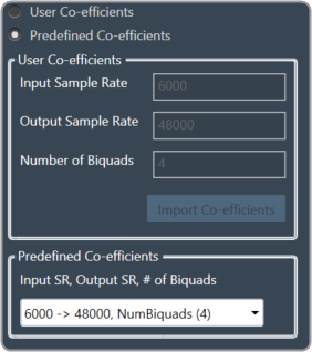
For these pre-defined coefficients, the quality measures are as follows:
- Signal to noise ratio: 80 dB
- Total harmonic distortion: 2e-3f
- Spurious free dynamic Range: 59 dB
- Total harmonic distortion plus noise: -60 dB
- Frequency response flatness: 3 dB
Output block length (Displayed as a read-only field) = (Output sample rate /Input sample rate) * Input block length.
17.6.Float to Fixed
Float to Fixed core object accepts audio buffers that are in floating point format and outputs buffers that are in fixed point format (16-bit, 24-bit, 32-bit etc).

- # of Channels is configurable. No of Input channels = No of Output channels
- The user can configure the scalar value to indicate what fixed point format is required. This scalar value is multiplied by the floating point input samples to convert them to fixed point.
For example, to convert from float to 32 bit fixed point, this scalar value must be:
(1 << (32-1) – 1) = 2,147,483,647 - In order to make routing from any core object to Float2Fixed object both the source core object and Float2Fixed core objects sample rate and block length should match.
Float To Fixed core object is enabled for audio libraries version 16 and greater.

17.7.Fixed to Float
Fixed to Float core object accepts audio buffers that are in fixed point format (16-bit, 24-bit, 32-bit, etc) and outputs buffers that are in floating point format.

- # of Channels is configurable. No of Input channels = No of Output channels.
- The user can configure the scalar value to suit the fixed point format of the input samples. The reciprocal of this scalar value is multiplied by the fixed point input samples to convert them to floating point.
For example, to convert from 32 bit fixed point to float, this scalar value must be:
(1 << (32-1) – 1) = 2,147,483,647 - In order to make routing from any core object to Fixed2Float object both the source core object and Fixed2Float core objects sample rate and block length should match.
Fixed To Float core object is enabled for audio libraries version 16 and greater.

17.8.Nan Detector
The NaN (Not a Number) detector core object detects NaN from input samples and informs the platform using an xTP command if NaN is found. The xTP command will inform about the core id, core object instance id and channel index, so that platform can react accordingly by muting or resetting states. The input samples are copied to the output without doing any other processing. The number of output channel(s) is always same as the number of input channel(s).

- # of Channels is configurable. No of Input channels = No of Output channels.
- Block length and Sample rate are configurable.
- The number of input channels is user configurable and ranges from 1 to 255.
- This core objects’ block length and sampling rate are the same at both input and output side.
- Block length is configurable in the range of 4 to 4096 samples.
- Sample rate is configurable in the range of 8 kHz to 192kHz.
In order to make routing from any core object to NaN Detector, both the source core object and NaN Detector core objects sample rate and block length should match.
NaN Detector core object is enabled for audio libraries version 19 and greater.