
1.Purpose of the Document
GTT is a customized branch of AudioArchitect from Harman’s Professional Division and Signal Flow Designer (SFD) is a specific additional functionality available in GTT, based on a separate extended license. This user guide will give you an overview of the use cases of SFD in GTT. For general information on how to use GTT, please refer to the Global Tuning Tool User Guide.
2.Overview
The Signal Flow Designer facilitates the creation of dynamic signal flows. The tool makes it possible not only to create a definition of a signal flow, but also to send it to the amplifier. Finally, it supports the on the fly creation of a device as GTT sees it (dynamic state variables creation for the audio blocks present in the flow) and is a launching platform for tuning panels (both native and custom).
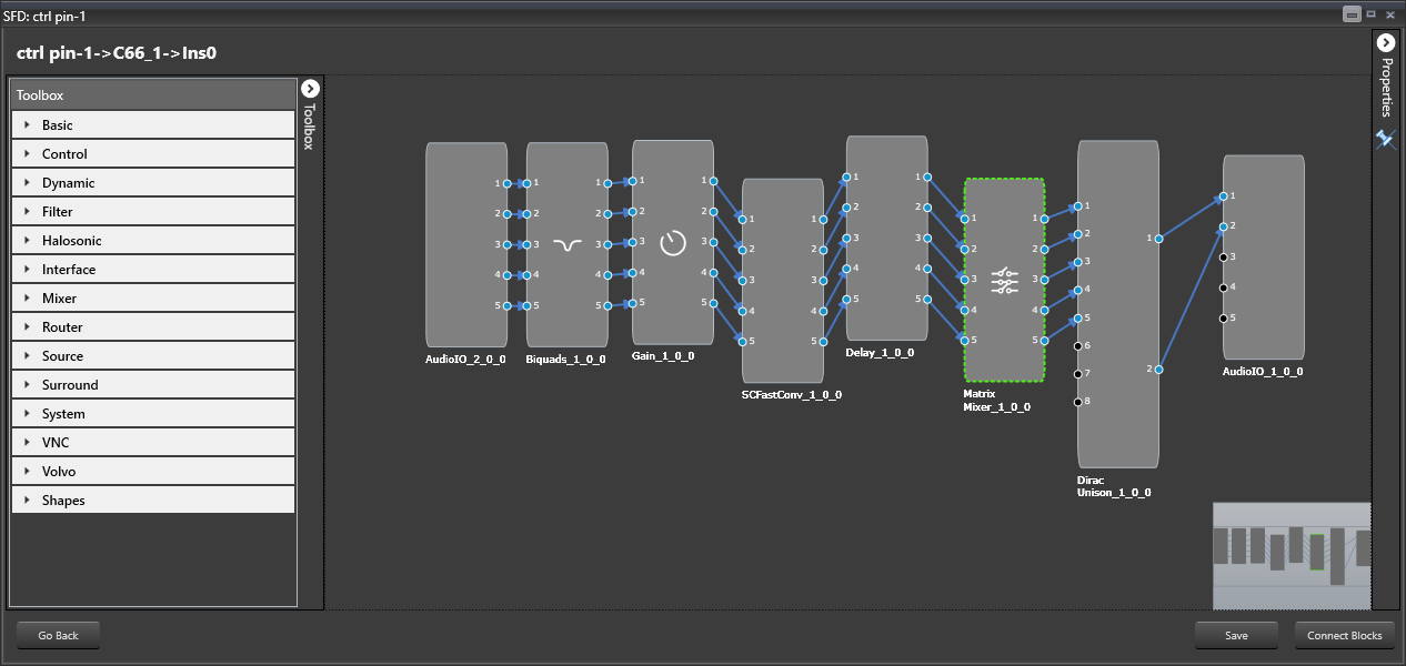
Example for a Designed Signal Flow
Refer to the Signal Flow Designer Startup Guide on information how to setup the Signal Flow Designer and corresponding software.
3.Create a Signal Flow
When at least one device is created, the user can start defining signal flows for the device.
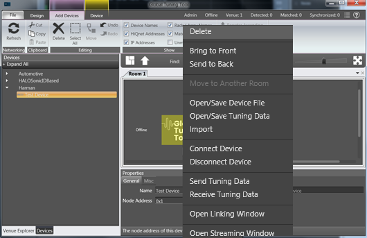
Open the GTT, click on a device instance in the room and look for tab Device. Signal flow designer can also be opened by double clicking on the device instance.
The GTT surface will be displayed.
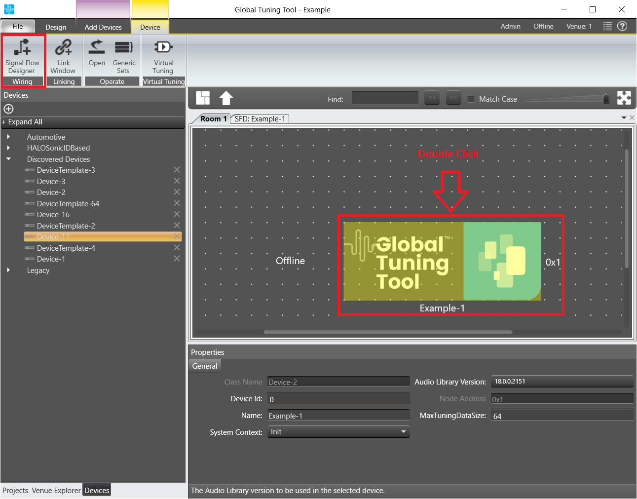
Double Click on instance to launch Signal Flow Designer.
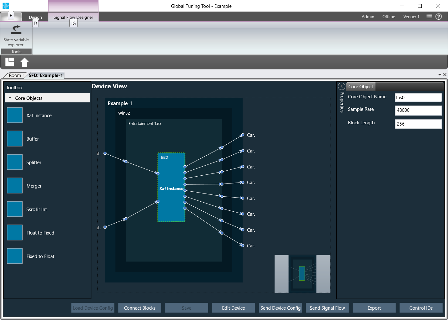
The Signal Flow Designer will be displayed.
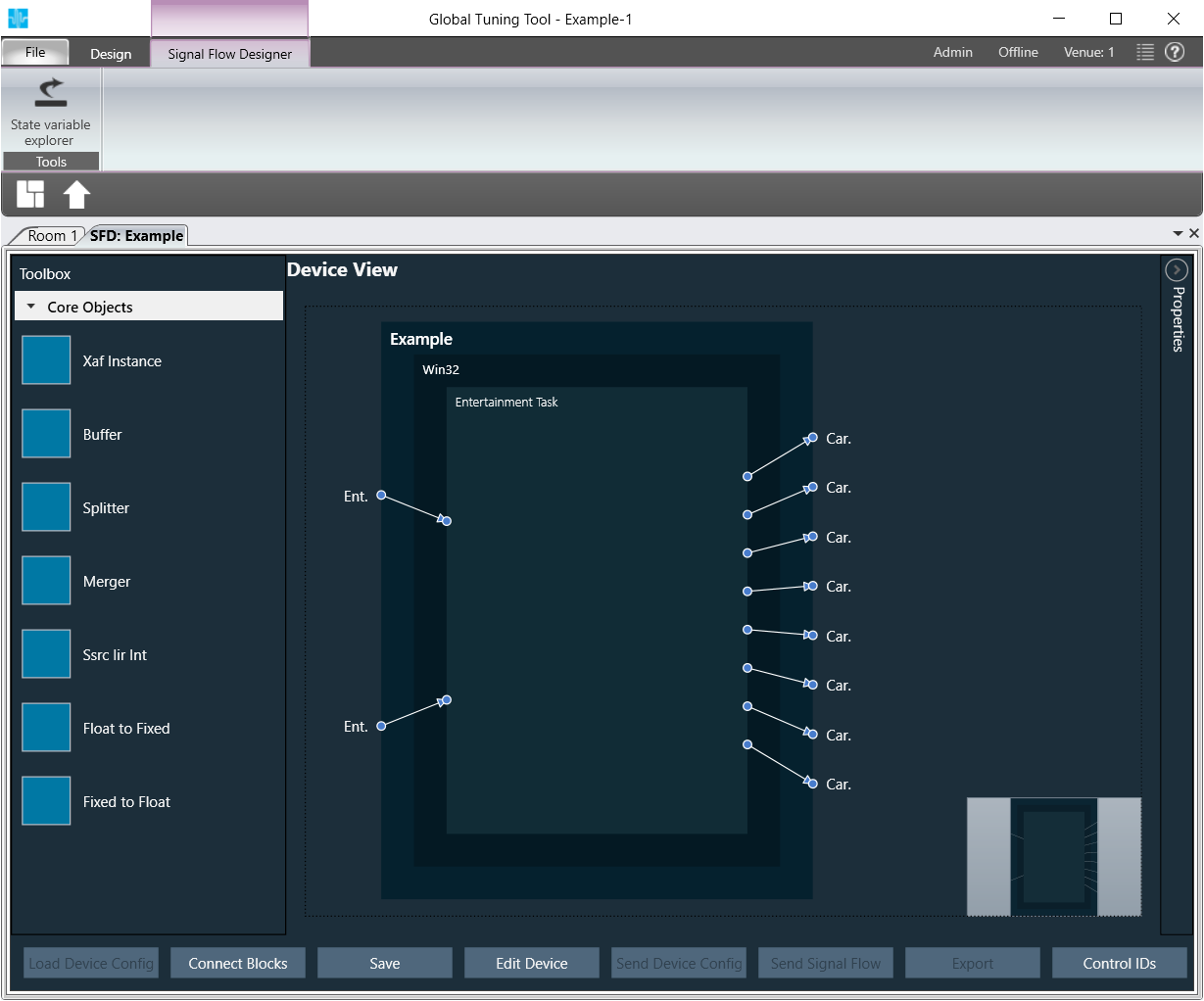
Click on the device you previously created.
One or several boxes will be displayed on the right depending on the number of cores you have configured for your device in the setup or how many cores your real device has.
On opening Device designer view, a notification would show up to inform the user to to verify the core type selections. User has the option to hide the notification on further usage.
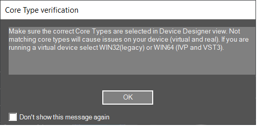
If you are running a virtual device select WIN32(legacy) or WIN64 (IVP and VST3).
Not matching core types will cause issues on your device (virtual and real).
The device view of signal flow designer has two modes:
- Static mode for manually created devices
- Wiring mode for discovered devices
Static mode
‘Load core objects’ and ‘Send Device Config’ are not available in static mode
In the toolbox there is only xAF instance, no further core objects
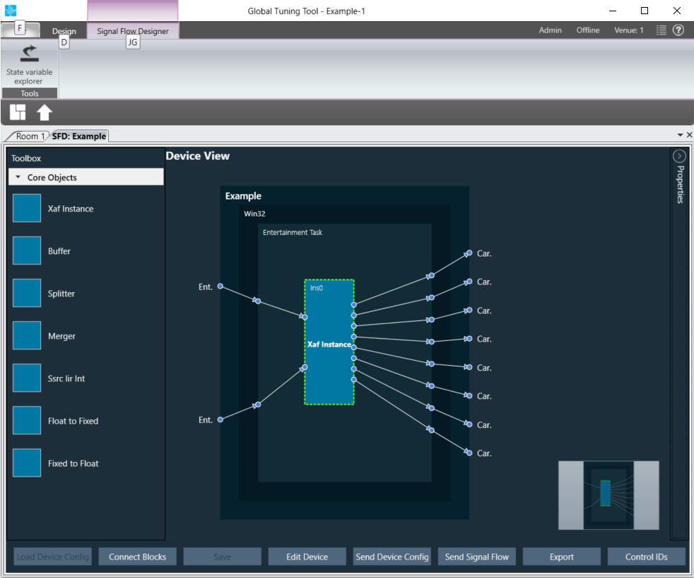
Add an xAF instance from the left box by dragging and dropping it in one of the virtual core(s).
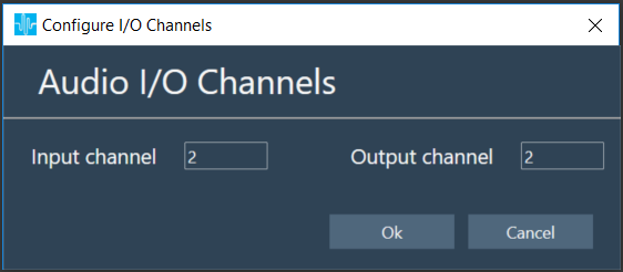
A popup window will be displayed where you can configure input and output channel count of the additional xAF instance.
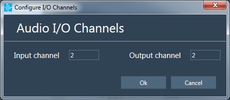
The instance will be represented by a blue box.
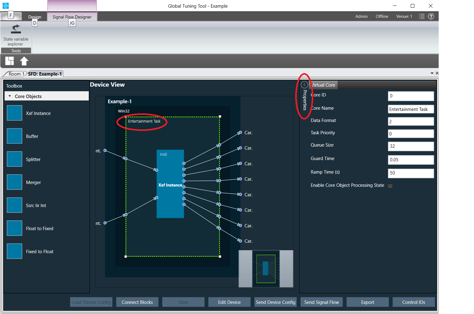
Select a virtual core and view core properties
Virtual core properties will be shown on left side.
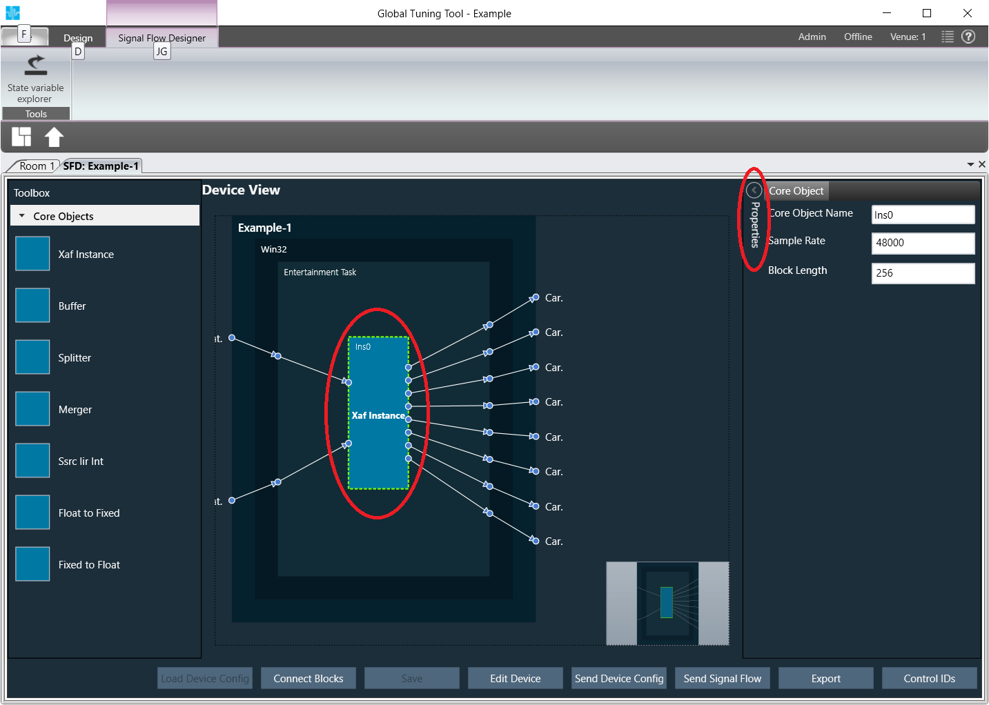
Select an xAF instance and view instance properties
Instance properties will be shown on left side.
Wiring mode
For further information on the new wiring mode, please refer to the GTT Basic guide in the section Device Identification – Load Core Objects
Functionality that is valid for both modes (legacy mode and wiring mode)
Click Save
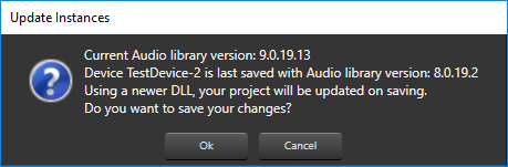
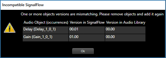
If there is a version mismatch between the current audio library version and version data present in the device, a warning message pops up
To proceed to the flow definition window double-click the added instance
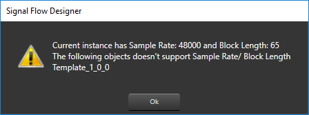
If there a mismatch between Sample Rate/ Block Length of instance signal flow and current audio object in the toolbox, then a warning message pops up and corresponding object will be disabled in the toolbox
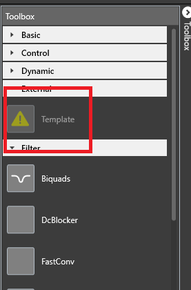
Disabled audio object
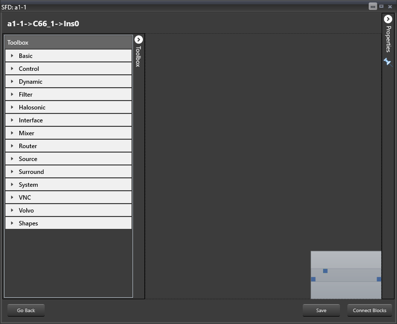
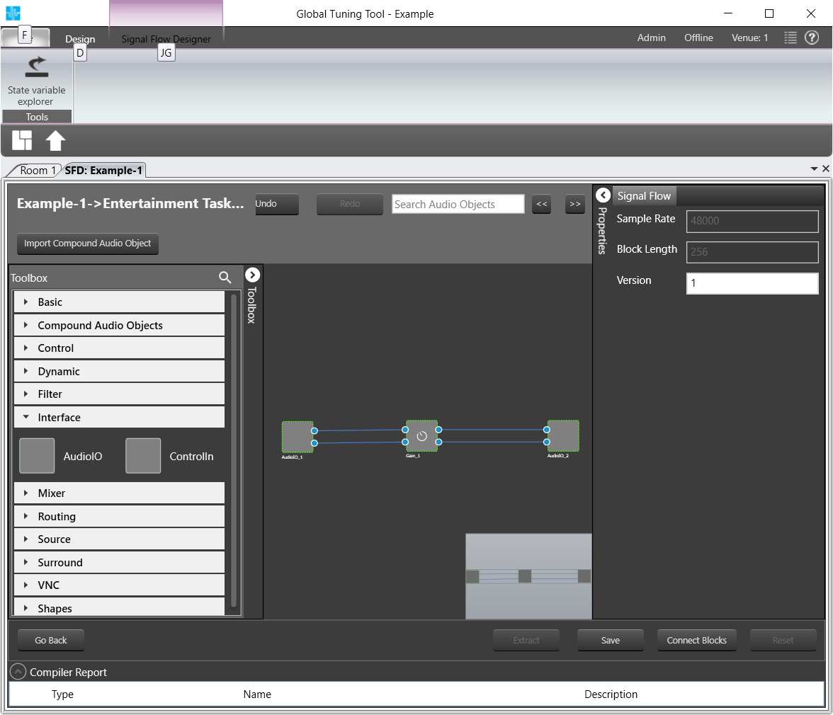
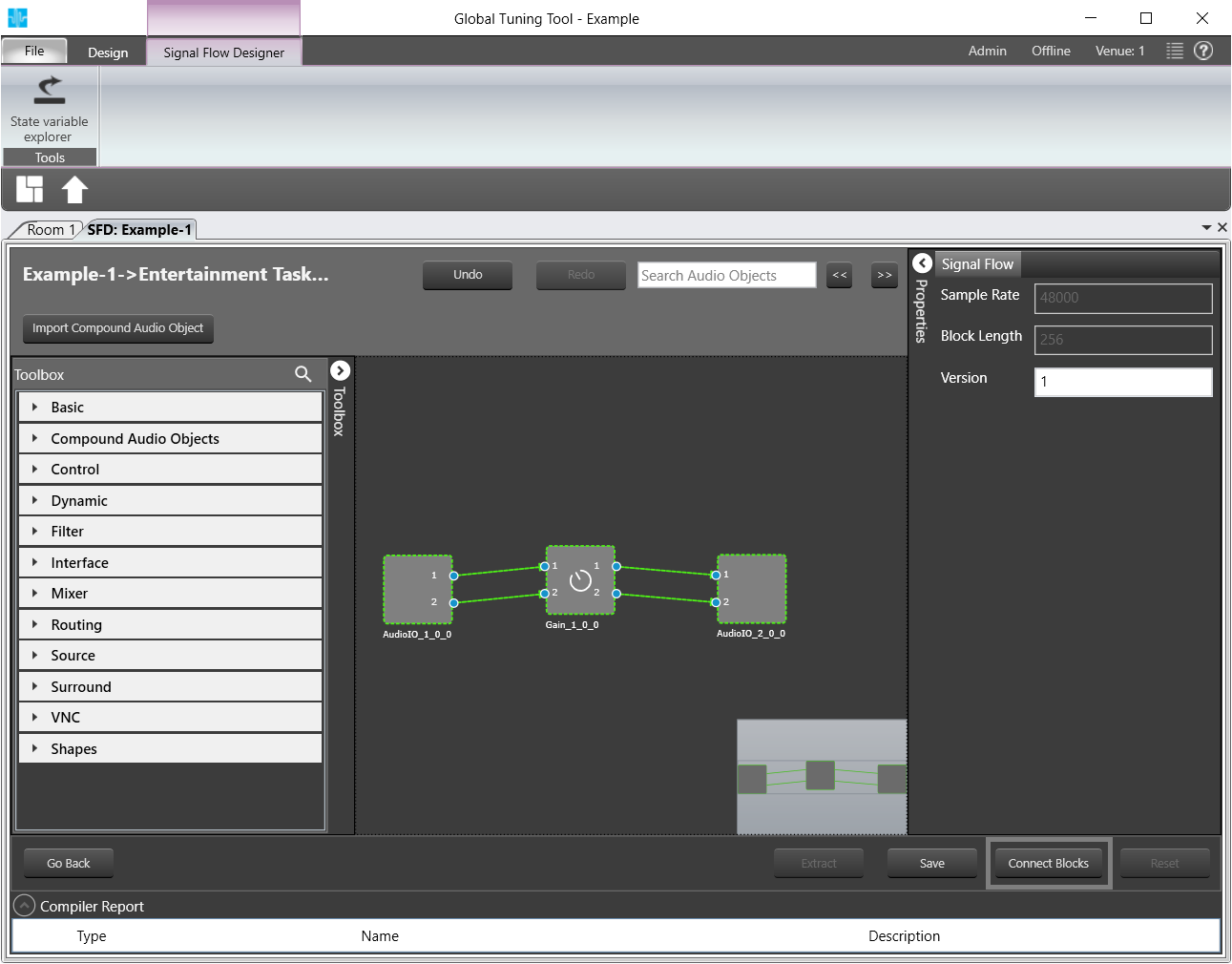
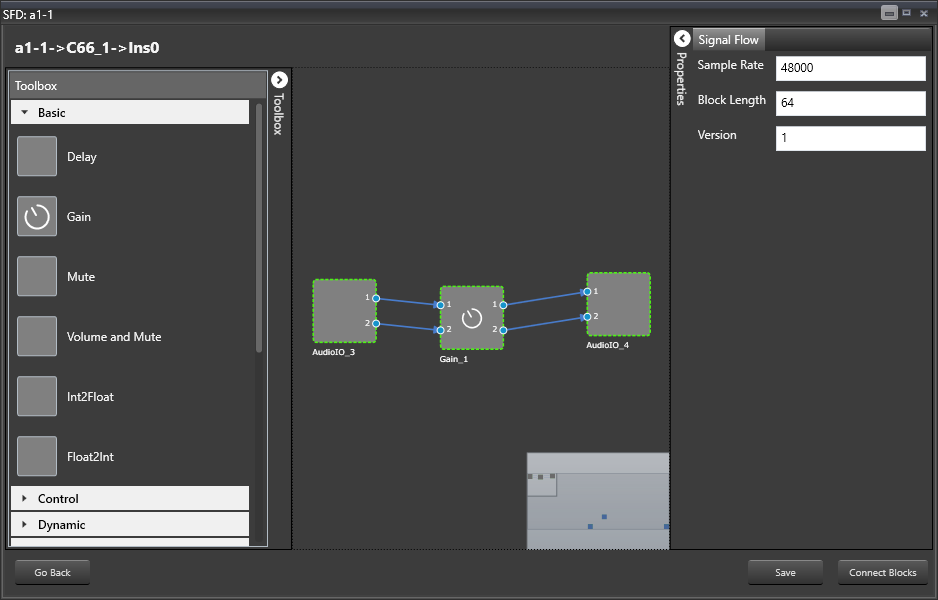
The flow definition window will be displayed, which contains 4 basic parts:
- Audio blocks toolbox (on the left)
- The designer area (center of the screen)
- Properties fly-in (on the right)
- Commands bar (at the bottom)
The first step in the signal flow definition process is filling in the signal flow properties:
- Sample Rate – this is the sample rate that will be applied to all the audio blocks in the signal flow
- Block Length – required internally by the xAF framework
Click on Properties.
The properties settings for the signal flow will be opened.
Now you can proceed to define the actual building blocks of the signal flow:
Open the category Interface from the Toolbox
AOs of the category Interfaces will be displayed.
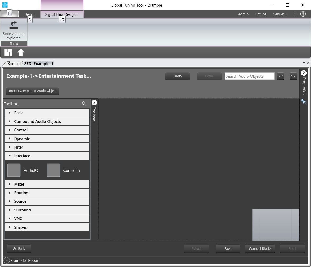
AOs of Category Interfaces
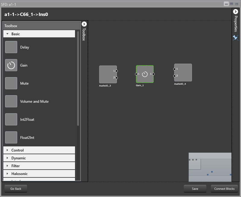
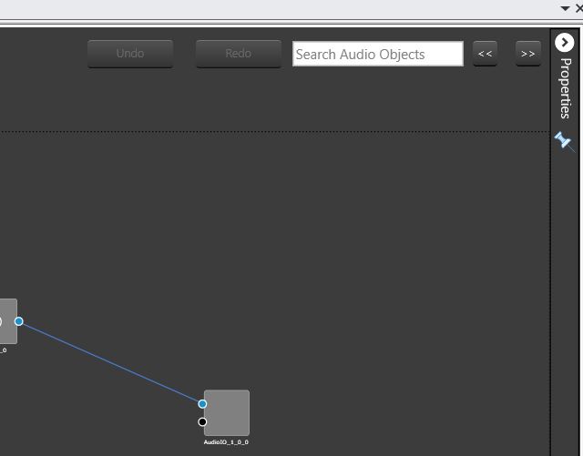
Drag and drop two AudioIO objects in the Signal Flow Designer
Drag and drop a Gain object from the Basic category in between the AudioIOs.
The AOs will be displayed SFD.
Select the Gain object and click on Properties at the top right of the window.
The properties menu for the Gain object will be opened.
Here you can modify the number of channels > Change to 2 channels for this sample.
The number of channels defines how many connectors will be assigned to the AO. You can assign as many channels as you configured for your device in chapter GTT.
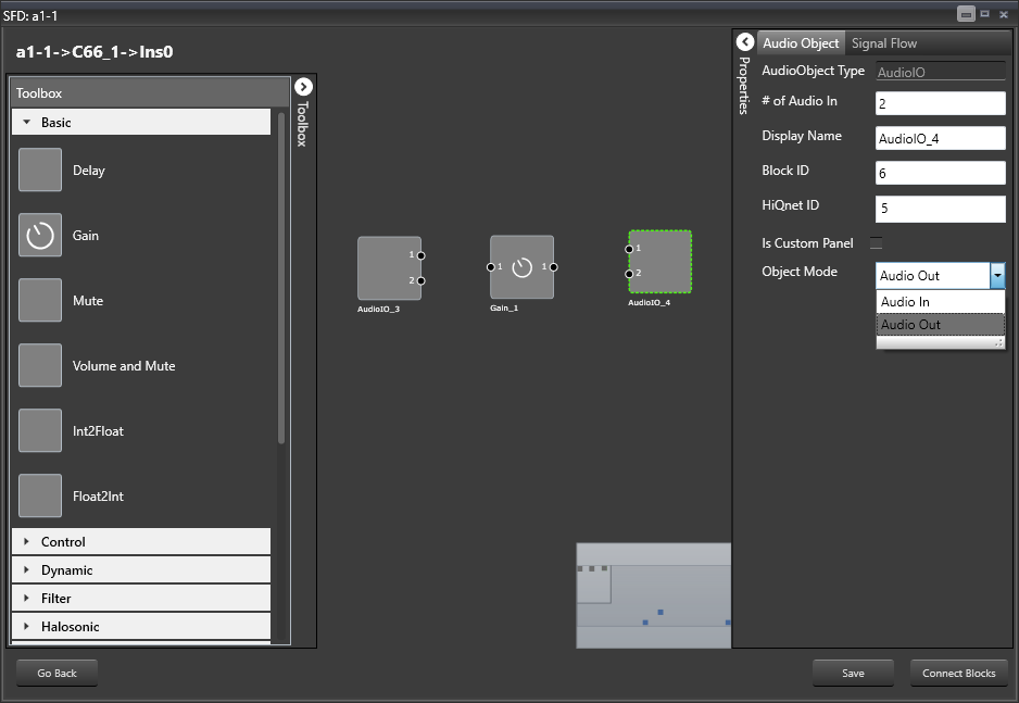
Open the Properties for one of the AudioIO objects

Select Audio Out from the Object Mode drop down menu.
Now you have an input and output object as well as an object to simulate sound volume change.
Hold Control and select all three AOs.
Click on Connect Blocks to connect the AOs.
Click on Save.
If there is a version mismatch between the current audio library version and version data present in the device, a warning message pops up asking to continue or stop saving
if there is Tuning version mismatch between Audio objects of signal flow and audio objects in tool box then warning message pops up showing tuning version differences and those audio objects are shown in blue color . Only after manually replacing these audio objects saving of signal flow is allowed.
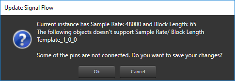
If there is a mismatch between Sample Rate/ Block Length then a message pops up asking to continue or stop saving
Click on Go Back.
Click on Send Signal Flow.
The message Signal flow successfully submitted will be displayed.
The Signal Flow has been sent to the virtual amplifier.
Auto-Connect Feature
For complex audio blocks that support multiple channels it might be time consuming to create connections manually. The auto-connect feature is there to facilitate that task.
Select at least two audio blocks (with CTRL key pressed) and push the Auto Connect button at the bottom of the screen.
The connections between the selected blocks should be created automatically.
The signal flow can be exported to .set file by clicking Export button at the bottom of the device in Signal Flow Designer. One .mcd file will be generated for master control data and one .Signal Flow Designer file will be generated per instance per core.
4.Tune a Signal Flow
In the following the tuning of a signal flow will be illustrated by showing the tuning effects on virtual device in IVP.
Double click on an Audio object
If SFD is modified, then a pop up will appear to save the changes
Save the changes
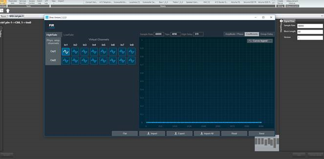
A Native Panel will appear, provided it is available for the selected audio object
The Signal Flow Designer will not allow the user to edit the Signal Flow as long as Native Panels are open
The property of any audio object can be viewed in the background while native panel are opened, but it is not possible to modify the data
If the Signal Flow Designer is open:
Close the Signal Flow Designer.
Your device will be shown in Room 1.
Delete your test device shown in the Room 1 section
Drag and drop your test device back in Room 1.
This action ensures that tuning of your signal flow will be matched in IVP.
Open the Signal Flow Designer as instructed in Create a Signal Flow.
Your previously created signal flow will be displayed.
Follow the instructions in Launch Native Panel above and launch the native panel for the Gain AO
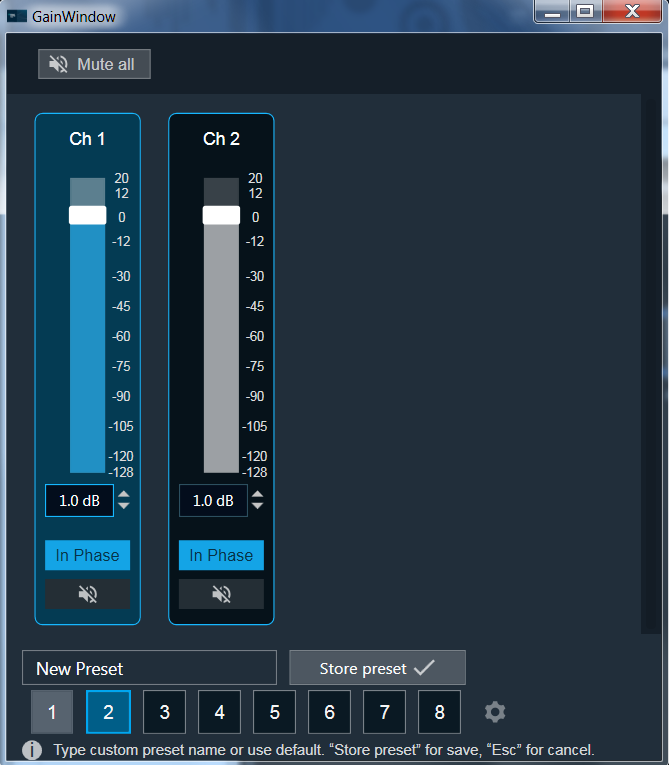
The Gain Window will be displayed. Here you can tune your signal flow once you have it visualized.
When a tuning is in progress, changes on signal flow is not allowed, including changes to connections. A toast message “signal flow cannot be modified when tuning is in progress” shows up
To visualize a signal flow you need settup the Analzer advanced settings in IVP.
Refer to those links for more information for Analyzer [link] and Generator [link]
All the audio blocks which don’t have a dedicated native panel yet should be associated with proper custom panels.
Follow the instructions in Launch Native Panel above to reopen the Gain Native Panel, if needed
To see how tuning in GTT affects your signal flow, proceed as follows:
Go to IVP, start Generator, start Analyzer, start PluginHost
Go to room and connect your Device, and send tuning data
Open Gain Panel
Go back to IVP
Adjust the panels in the Gain Window to tune your signal flow.
Your signal flow in IVP will change according to your tuning.
5.Additional Audio Block Configuration Parameters
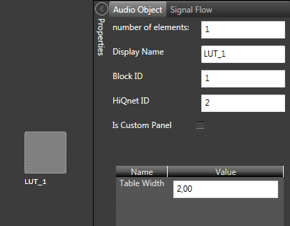
There are AOs for which the default set of configuration properties (# of channels, audio inputs, audio outputs, and elements) is insufficient. The LUT object is a good example – user needs to be able to specify both the number of rows and columns in a look-up table. For that purpose, the concept of additional configuration parameters has been introduced and implemented both in GTT and xAF.
Theoretically, an audio block can have any number of additional configuration parameters. Parameters definition are taken from the xAF library along with the parent block definition. A parameter definition consists of the parameter order, name and value. For now, parameter values are represented as floats. It is planned to extend a parameter definition to support multiple parameter types in the future.
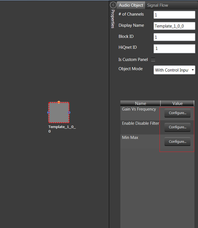
The parameter definition also has some extra metadata like dimension group which help to display additional parameters in Tabular UI. The below image shows how additional parameters will display when there is a dimension group metadata available.
Click on “Configure…” button
The system will open additional parameters in a tabular window, where you can provide additional parameters.
These additional parameters are of same data type which is provided as part of parameters definition.
Once done with your changes, click on “Apply” button
the system will apply the defined additional parameters
alternatively you can click on “Cancel” to close window without apply.
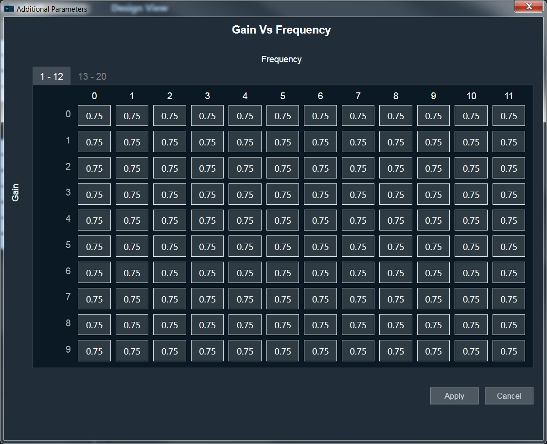
The above image is an example for 1-dimensional additional parameters.
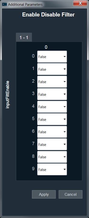
Dynamic Additional parameters :
This feature is to change the size of additional parameters based on IO modifications. This feature is available for selected Audio objects which have “isAddVarUpdateRequired” flag set in their static metadata.
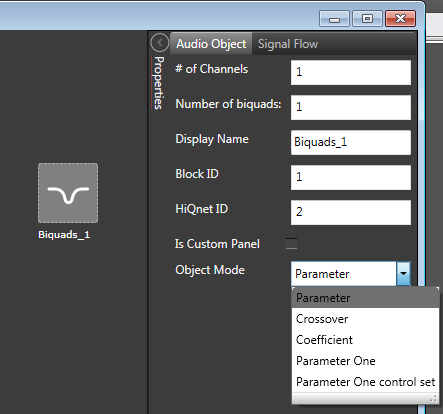
6.AO Modes
Certain audio blocks support multiple configuration modes. For example, the AudioIO block can serve either as an audio input block or as an audio output block, the Biquads block can work as either parameters-based or coefficients-based Biquad, and so on.
In the previous version of the Signal Flow Designer in GTT, each mode of an audio block has been represented as a separate audio block. This has changed in the latest version of the tool. It has been implicitly assumed that every block supports at least one configuration mode. For those blocks that support more than one mode, an additional drop-down field is displayed in the configuration tab. You can change the mode by choosing a relevant value from the drop-down.
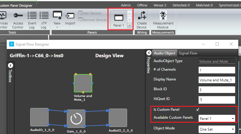
7.Control Configuration
The latest version of the SIGNAL FLOW DESIGNER in GTT supports control routing from the control hub (Master Control) to xAF framework instances.
A control flow for each instance is configured via the ControlIn block. A user can choose which control signals will be routed to an instance by assigning them to output pins of a ControlIn block in that instance. A new tab has been added to the configuration fly-in to facilitate the process. Using that tab, you can choose from a wide list of available control signals and associate them with control outputs of the ControIln block. Re-ordering of the items in the control signals grid is done via the Up and Down buttons.
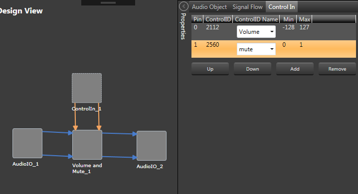
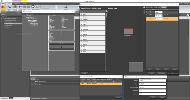
You can also define your own custom control signals (Control IDs) and assign them to control pins. There is a dedicated button at the bottom of the Device Designer screen which opens a window that shows a list of custom control signals defined for the device. You can create, update and remove custom control signals in that window. If any custom Control IDs are defined for a device, they are available in the Control In tab of any Control In object, similarly to the predefined Control IDs. As far as tuning is concerned, custom control signals become a part of the Master Class object, just like predefined control signals.
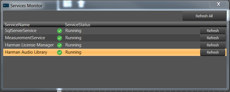
8.Harman Audio Library Service
The HAL service is a wrapper around the xAFVirtualAmp library. It’s been created mainly because GTT is a 64-bit application, while xAFVirtualAmp is a 32-bit library, hence it is not possible to launch both binaries in the address space of the same process. Internally, the HAL service is implemented as a WCF service hosted in a Windows service. It communicates with GTT via named pipes. HAL exposes the following xAF API to GTT:
- getAudioToolboxBuffer – returns the AudioToolbox.xml file as a string. AudioToolbox.xml contains definitions of audio blocks known to a particular version of the xAFVirtualAmp library.
- getIoObjectInformation – the method accepts audio block configuration parameters and returns the IO layout of the block (# audio ins, # audio outs, # control ins and # of control outs).
- getTuningInformationBuffer – returns a device description snippet for an audio block. Iterative invocation of that method for each audio block across all framework instances produces a device description file.
The HAL service should be started by default after a successful GTT installation.
If that’s not the case or the service has turned off for one reason or another (the application communicates such situations via error messages):
Go to the GTT Service Monitor.
Choose Harman Audio Library.
Press the Refresh button.
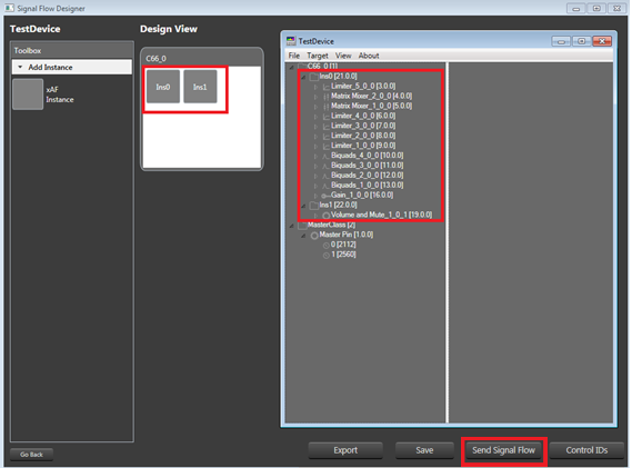
9.Support for Multiple Framework Instances
By default, the xAF framework supports only one core and one instance running on that core. However, it is possible to create a customized xAFVirtualAmp build that supports multiple framework instances, spread across multiple cores. Currently, it’s done by the means of hardcoding the audio routing between cores at the device level and between instances at the core level. In the future, it will be possible to provide the routing configuration using GTT. For now, the tool makes it possible to build signal flows consisting of multiple cores and framework instances, as well as to generate device descriptions for such setups. However, a user must know the audio routing hardcoded in the xAFVirtualAmp library up front and respect its limitation when creating a multi-core, multi-instance layout.
Once the design is done, you can send a complete configuration (control configuration for a device and signal flow configurations for each framework instance) to a real or virtual device. In order to do so:
Go to the Device Designer view in Signal Flow Designer and press the Send Signal Flow button in the bottom-right corner of the designer window.
10.Pin Labelling
A signal flow designer user can assign labels to audio and control pins of audio objects to make a flowchart design more informative. There are two new items available in the context menu of each audio object: Add Audio Pin Label and Add Control Pin Label.
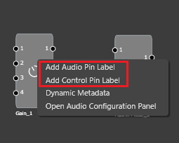
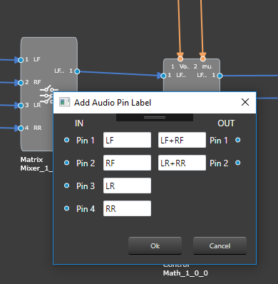
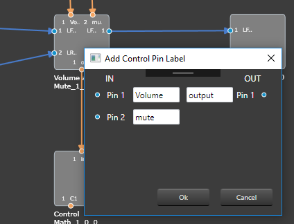
Click on one of the items to bring the pin labeling widget into view.
It presents existing pin labels and lets a user modify or remove them or add new ones.
By default, pin labels do not propagate downstream, but for certain objects (e.g. Gain, Biquad or Delay) they do. So, if there are four blocks in a design – AudioIn, Gain, Delay and AudioOut, it’s sufficient to label the output channels of the AudioIn block, select all the blocks and press the Connect Blocks button to propagate the labels.
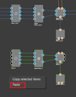
11.Copy and paste
Copy and paste is another convenient feature of the signal flow designer, which speeds up the design process.
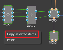
Select an object and press CTRL+C or right-click the designer area and then click the Copy selected objects context menu item.
Paste the object into the same or a different framework instance by pressing CTRL+V or clicking the Paste context menu item.
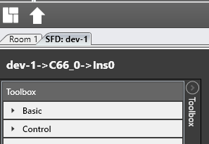
12.Docking and undocking of SFD
By default, the SFD window is integrated into the GTT document layout and appears as a tab in the document host.
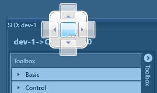
Click on the header of the SFD tab and drag it out of the document host. The complementary operation is possible as well.
If you drag the SFD window over the document host, a blue indicator will appear. Dropping the window on the indicator will convert it into a tab again.
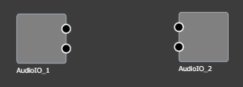
13.Audio inputs and Audio outputs
Have Audio In and Audio Out always in a blank design
A new window to configure the number of Audio inputs and Audio outputs is displayed immediately after the instance is dropped into the core. And the configured Audio In/Out blocks are displayed by default once the Signal flow designer view is opened.
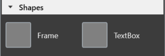
14.Frame and Textbox
Added 2 new objects into the Signal Flow Designer Toolbox.
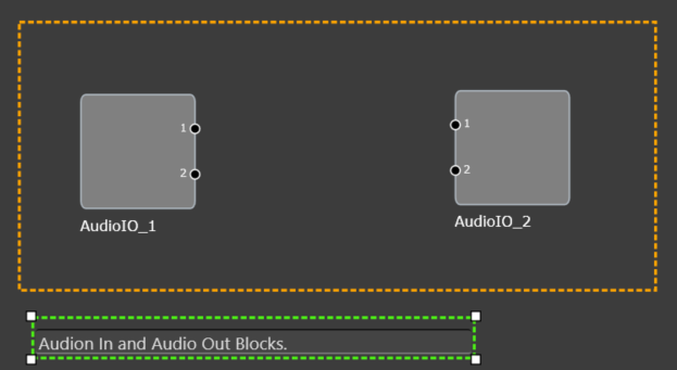
By default, irrespective of the audio Library, two objects are always available in the Toolbox. These objects (Frame and Textbox) are available under the Shapes category. These objects are not audio objects and they are not considered for tuning and while sending the signal flow to device.
The Frame object can be used to highlight certain blocks in the signal flow designer. Whereas the Textbox object should be used to provide additional information to the user of the Signal Flow.
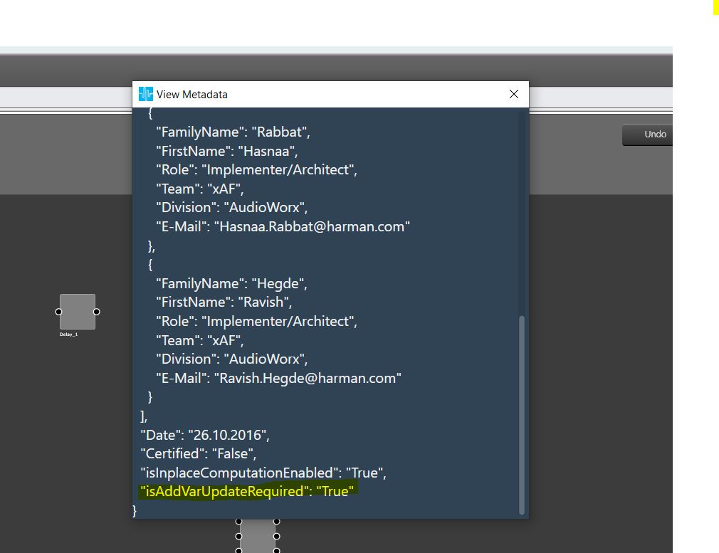
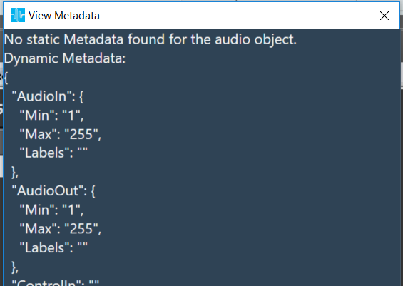
15.Display Audio object metadata in GTT
By default, every object available in the tool box will have a context menu item to let a user inspect the Static metadata related to that object’s type.
Every audio object instance in the design area will have a context menu item to let a user inspect the Dynamic metadata related to the object’s instance.
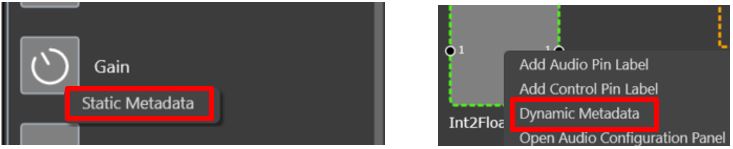
Click on the above context menu item.
A new window is displayed which has displays the metadata information.
16.Tooltip for Audio Connections
There are tooltips available that will provide more detailed information on the connection between AOs, showing the affected Audio Object’s names and the respective pins used.
In order to see these tooltips you need to
Connect any two audio objects
Hover your mouse over the connection presenter (Arrow)
A tooltip is shown for the connection, displaying the Audio Object Name, Pin No., Labels (if exists) for the connected objects.

17.Change Processing state of an Audio Object
In the Daily basis need Audio Engineers required to do A/B testing of Signal Flows, as well as load balancing. Along with that need easier way of debug tuning data in case of errors experienced.
To achieve the aforementioned functionality GTT Signal Flow designer has provided rich support through context menu of Audio Object. Using these options i.e. Normal, Bypass, Mute and Stop, the Audio Object’s processing state can be changed.
These menu options are available only when device is connected.
Audio object which has a state other than ‘Normal’ cannot be tuned through Native Panel.
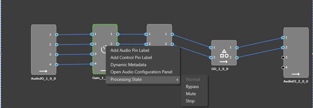
These options are available to all audio objects except interface objects like Audio-in/out, Control-in/out. For the compound audio object, the selected state will be apply to all inner audio objects.
Following are the tasks carried out on the xAF side for each state:
- Normal – Normal operation with update of necessary internal states of the audio object; normal output.
- Bypass – Normal operation with update of necessary internal states of the audio object; input channel buffer data copied to the output channel buffers.
- Mute – Normal operation with update of necessary internal states of the audio object; output channel buffers cleared.
- Stop – Input channel buffer data copied to the output channel buffers (no update of internal states).
Through GTT, the above states can be selected only for the regular audio objects and for source objects like Waveform generator, only Normal and Mute states are allowed.
Ramping:
To ensure smooth transition across states, linear ramping is provided with the ramp-up OR ramp-down time of 50 ms. Ramping is not provided for any transitions involving Bypass state and the individual audio object need to support this.
For transition between Normal and Stop states, first the output is ramped down from the present state to mute state and then ramped up to the target state.
Every time user connects to device, audio object states from device are read and applied to signal flow designer.
If user reboots the device, processing states of Audio Objects will set to ‘Normal’.
In signal flow designer user can reset all audio objects processing state to ‘Normal’ by using ‘Reset’ button.
18.Upgrade audio object
Overview
Signal flow validates audio objects with currently loaded audio library tool box. Until N-release, if there are any objects that is not in sync with the audio library, GTT will not allow to save the signal flow or send the signal flow to device. User has to replace (delete) manually the current objects within the signal flow, with the toolbox object to pass the validation. In this process, all the connections and tuning data are lost, which have to be redone, thereby resulting in increased effort.
Henceforth, the “Upgrade audio object” feature helps make this process more efficient. User can select the option to upgrade audio object, Application automatically upgrades the audio object to the latest tool box state.
Automatic Upgrade of audio objects
When signal flow is launched by double clicking on the Framework instance in device view, GTT validates all the audio objects that is mismatching with the toolbox and a report is shown with version difference and offers to auto upgrade them based on user choice. If user clicks Yes, then all the audio objects are upgraded automatically to make the version equivalent to toolbox version. If there are any compound audio objects. They have to be manually upgraded.
If user chooses No, the signal flow is launched and user is let to manually upgrade them.
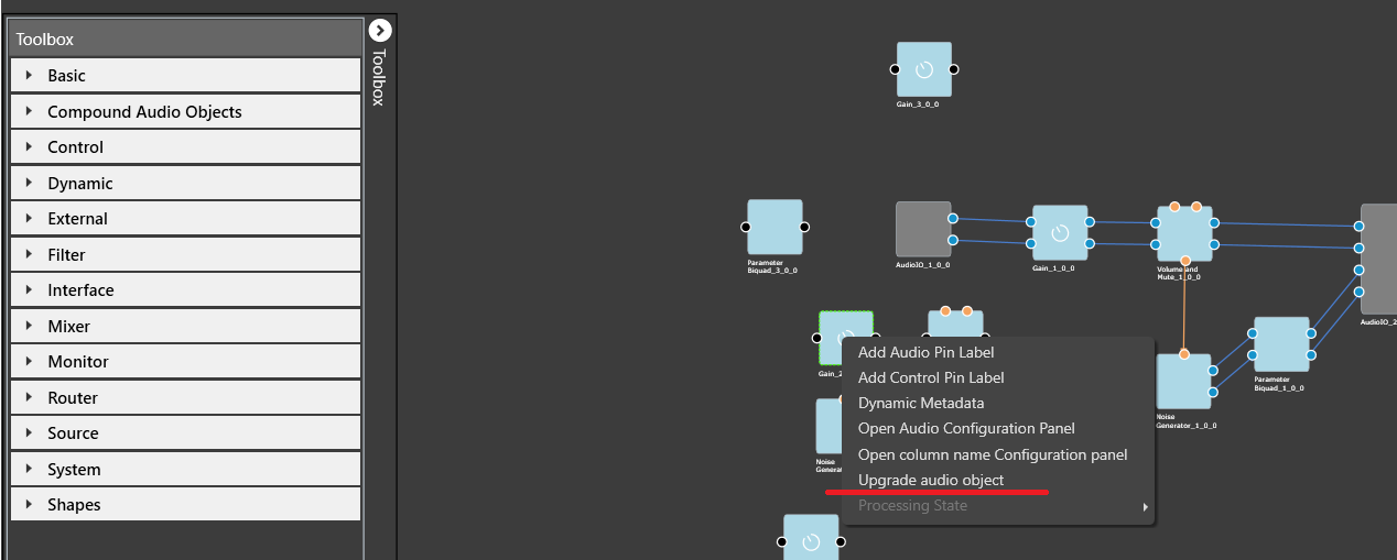
Manually Upgrade an audio object
Below image shows the context menu option to choose “upgrade audio object”. When the audio object is upgraded, there will be messages to guide the user to the next steps.
Following properties of audio object will be upgraded:
- Additional variables (added or deleted)
- Modes (added or deleted)
- Audio object properties like input/output, channels, etc
- Tuning version
Audio objects which have Tuning Version major change or with any structural change like additional variables changes will be detected as incompatible and will be highlighted in blue color. Signal flow cannot be saved until all these incompatible AOs are upgraded.
Tuning data and parameter sets will be retained for minor version changes in Tuning version. Major version change will not retain tuning data and parameter sets. Eg: If tuning version of an audio object in the signal flow is 04.00, and in the toolbox the version is 04.01, here only the minor version has changed. Hence the tuning data will be retained. On similar same lines, if tuning version of an audio object in the signal flow is 04.00, and the toolbox version is 05.00, here tuning data will be lost as the AO internal structure has changed.
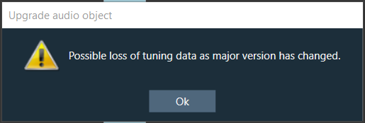
Once the upgrade has finished, there will be a message to inform user about the tuning data status.
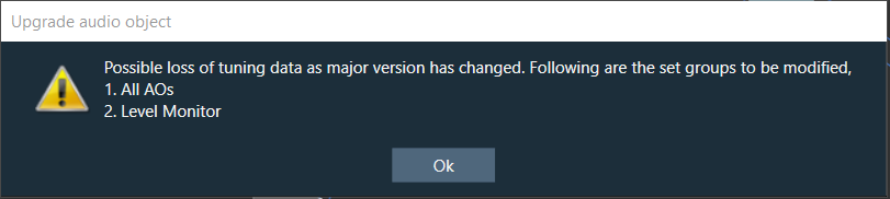
The above message is a caution to user that there is a possible tuning data loss as audio library changed the major version in Tuning version. The set group(s) to be modified will be listed in the message.
If no set groups are created using the respective audio object, following message will be shown,
The below message is an information to user about the successful completion of upgrade.
Upgrade Compound Audio Object (CAO)
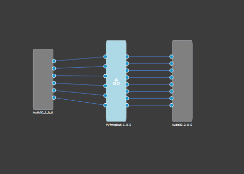
Compound audio object in the signal flow can also be upgraded. In the case of CAO, minor version change will only upgrade the version number and nothing at all. If there is major version change in the toolbox, then internal audio object will be updated to latest version as per the tool box CAO type. In the cases of major version change and inner objects cannot not be automatically upgraded, CAO will be marked with blue color and user shall take the following steps for the CAO upgrade: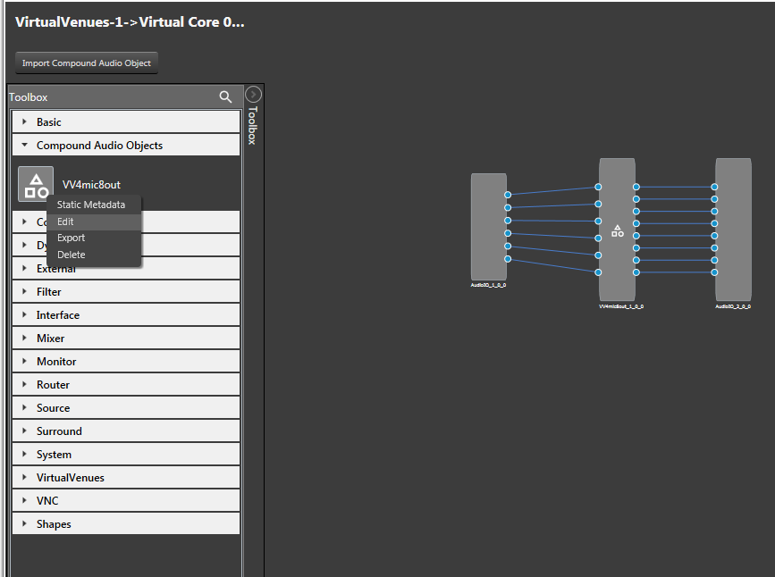
- Enter the edit mode of the CAO, to view the signal flow of the internal audio objects.
- Upgrade the internal audio objects as described in the previous section. Save and Go Back.
- Upgrade the entire CAO.
If the block id is changed form normal format to extended format in the dll, upgrade of block id is not supported.
19.Undo/Redo of SignalFlow
Undo redo feature is now implemented in the signal flow view as a beta version.
Important: Undo redo feature is not yet available in the tuning flow view.
Signal flow designer Undo/Redo
- Undo/Redo operation is supported for the following actions
- Add/Remove of audio objects
- Add/Remove of audio object connections
- Audio object movements
- Audio object property changes
- Additional parameter, Additional parameter config changes
- Pin label, connection label changes
- Copy/Paste of audio objects
- Audio object processing state actions
- Extract CAO
- Undo/redo action can be done using these buttons in the Signal Flow Designer
- The scope of Undo/redo will be within the specific instance
- In some cases toast message appears to help invisible items getting undone or re-done.
- Additional parameter config panel changes
- When processing state cannot be applied
This feature is limited to 1000 actions.
When a new manual action is performed, Redo stack will be cleared.
20.Audio-object Toolbox Search
Search can be performed on Audio-object toolbox in SFD.
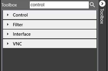
Click ![]() to search
to search
Search box will be displayed. On entering 3 characters or more , toolbox will be filtered.
When search box is cleared or clicked on ![]() again, filter would be cleared.
again, filter would be cleared.
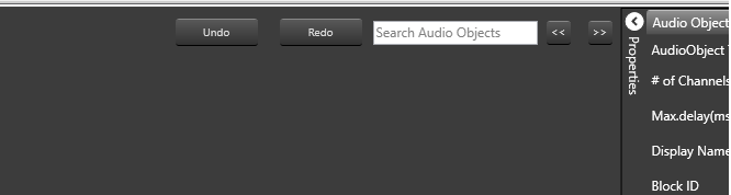
21.Search Audio objects in Signal Flow
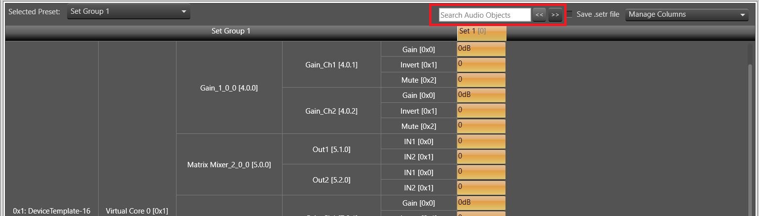
A text box is available on the top right corner of the window to search audio objects inside the signal flow designer area.
At least 3 characters needs to be inputted to enable the search. The Audio objects search would be performed based on the Display Name of the Audio object. The searched audio objects would be highlighted in yellow color.
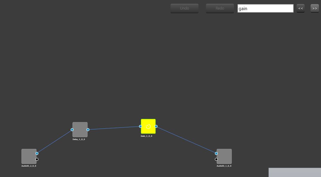
The “<<” and “>>” buttons could be used to navigate between the highlighted audio objects. The highlighted audio object would be re-positioned to the center of the screen after clicking “<<” or “>>” (search buttons).
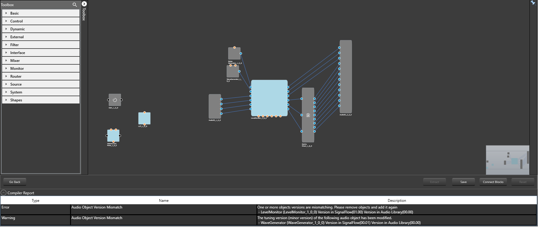
22.Signal flow compiler report
Signal flow can be invalid due to following reasons.
- Tuning Version in Audio object is different than Audio Object type exists in Device Associated Audio Library.
- Additional Parameters or Audio object Mode, (or some other parameters) might mismatch in Audio Library and Audio objects in signal flow.
In the above mentioned scenario, compiler report will have warning/Error entry item for each invalid Audio Objects as shown in below picture.
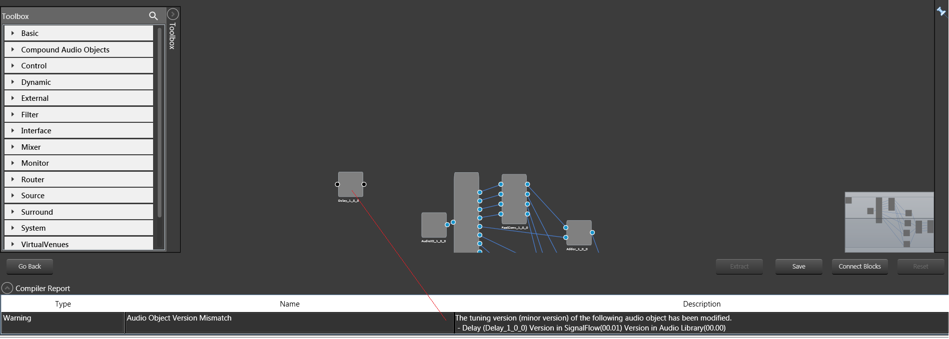
In the above pic , delay object has minor tuning version mismatch with current loaded Audio Library. Hence warning displayed in compiler report.
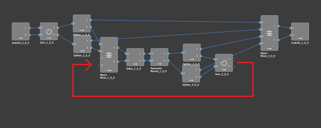
23.Feedback loop in signal flow
GTT does not support feedback connection in signal flow. For example it is not possible to connect Gain_2_0_0 to Matrix_Mixer_1_0_0 in below Signal Flow, as this connection leads to loop.
Hence if user tries to connect any audio objects which will leads to loop, a notification is shown that “Connection is not possible”.
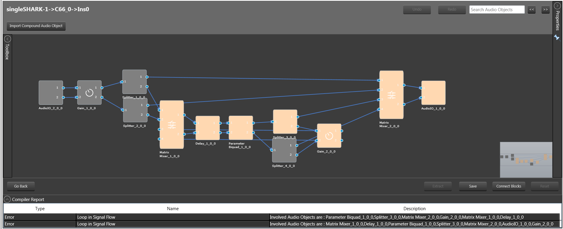
For legacy project :
If signal flow already has a feedback loop, in that case designer will highlight Audio Objects in loop and compiler error will be reported as shown below.
To save signal flow user has to remove existing loops.
There is no restriction to add loops in control signals.
24.Validations in Additional parameters window
GTT will validate the user inputted data in the additional parameters window. The validation will be done based on the information provided by the xAF dll for specific audio object(s).
The below validations are added on xAF and GTT.
- ASCENDING
- DESCENDING
- NOTEQUAL
- EVEN
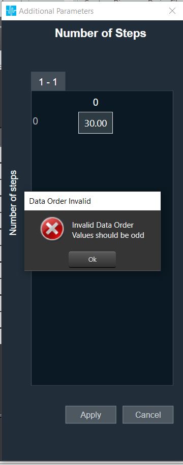
- ODD
- EVEN_ASCENDING
- EVEN_DESCENDING
- ODD_ASCENDING
- ODD_DESCENDING
The below screen shot displays that the value entered should be an Odd value. An error message is displayed to the user when an even value is entered.
25.Device and Node Validation
When there is a problem with DDF generated by toolbox while creating the device or modifying the signal flow user will be notified with the error. GTT will consider the incomplete\failed audio object as corrupt. User shall correct DDF template of that audio object and continue working.
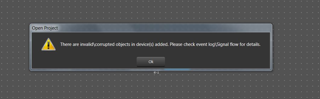
On importing a project Or while opening a project which has corrupted audio object, following warning message will be displayed.
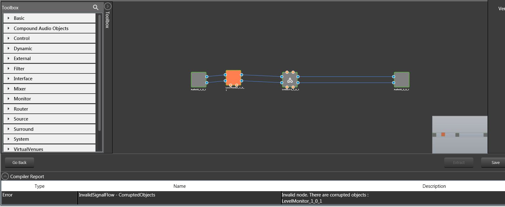
On opening the signal flow which has corrupted object, corrupted audio object will be highlighted as shown below and same will be displayed in compiler error window.
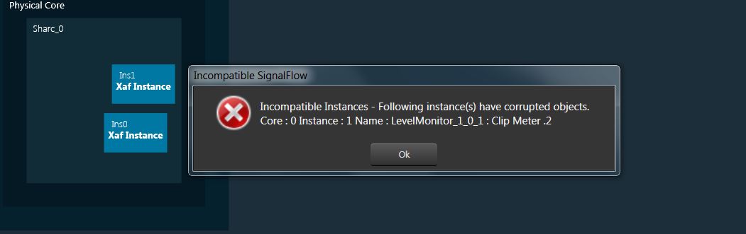
If the signal flow has corrupted objects on sending\exporting signal flow, following message will be displayed.
26.Search in Parameter Sets
A search box is available on the top right of the window to search parameter sets by Audio-object name.
At least 3 characters needs to be inputted to enable the search.
On search for Audio-object name, matching audio-objects containing searched key, would be highlighted in yellow color and navigation to first matching row is automatically performed.
“<<” and “>>” buttons can be used to navigate between the highlighted audio objects.
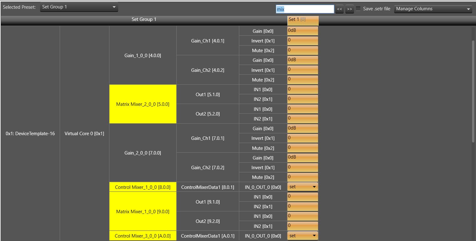
Search results would be cleared when row is added or deleted from parameter sets and on switching to different Set Group
27.Block Control
This feature enables signal flow designer to group multiple control signals into a block control
- Audio objects needed or block control signal to control signal conversion and vice – versa
- Control grouper: Facilitates SFD user to group the control signals into block control
- Control Splitter : Facilitate SFD user to split the individual control signals
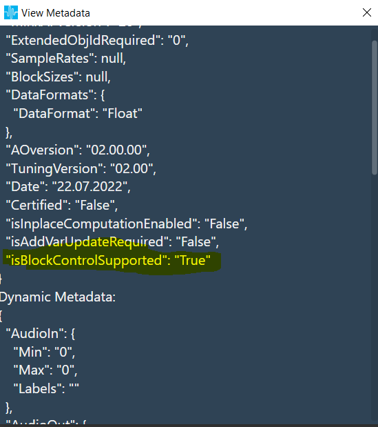
- Any audio object which supports block control should declare a flag in dynamic metadata as below.
UI Support for block Control
Block control connections will be highlighted as thick lines in both in SFD and CAO signal flows.
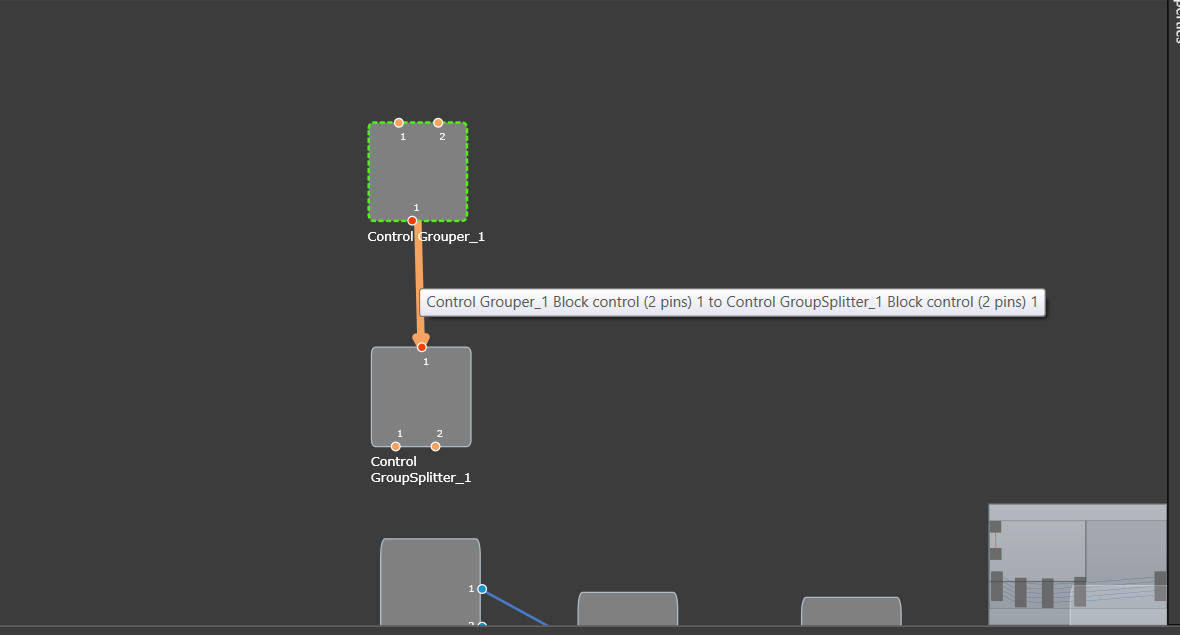
Block control pins are in dark orange color and on connection mouse hover block pin details are displayed as above.
Validations:
- It is possible to make block connections only when the group count matches. Else a validation error will be thrown.
- If the group count is 1, it is possible to connect normal control pin with block control pin.
28.Securing Audio Objects
Using “Lock\Unlock” functionality you can secure audio objects. This will help you to safeguard Harman proprietary audio objects during collaboration. This feature encrypts Harman audio objects within the project, preventing unauthorized access by third parties. Additionally, you can hide the tuning data, ensuring sensitive information remains confidential when sharing the projects.
Characteristics of secured audio object:
- Secure audio objects will not allow any of their properties to be edited. The Properties window will be disabled.
- New secure audio objects cannot be added to the signal flow.
- There is no way to remove, duplicate, or copy a secure audio objects.
- Upgrade of secure audio objects is not possible. Error message will be shown to use the valid framework dll.
- Native panel cannot be opened from the signal flow or custom panel.
- If any secure audio object has been configured in custom panel before locking, it will continue to work. However, after locking it is not possible to add secure audio object native panel to custom panel. Secure state variables will be disabled in address assignment window.
- Secure audio objects will be hidden in Sate Variables explorer, MIPS, Memory, Memory Latency, and Streaming window.
- It will not be possible to export the DDF of the device which contains secure audio objects.
- In the XTP viewer, secure audio object’s tuning will not be decoded.
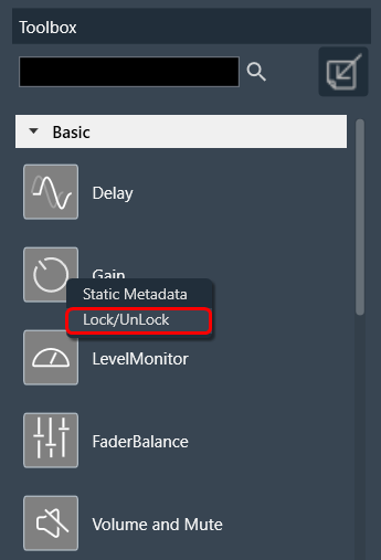
In the toolbox, you can use “Lock/UnLock” option available on right-click of any audio object to secure any audio object. Once the audio object type is locked (password protected), all the instances of that audio object type will be locked across all the projects. The locking of audio object feature is audio library specific.
Once the lock is applied to any audio object type, following changes will take place in the system.
- Locked audio objects are distinguishable from other audio objects with lock symbol.
- Lock is on all instances of the particular audio object type across all projects based on the selected audio library version.
- Audio object will be locked in CAO instances. However, CAO types are excluded.
- When “Open Signal Flow for Tuning” is clicked on the Instance, the audio objects will remain locked.
- Audio objects remain locked in CAO instance signal flow
- Undo and Redo history will be cleared from the Signal Flow Design.
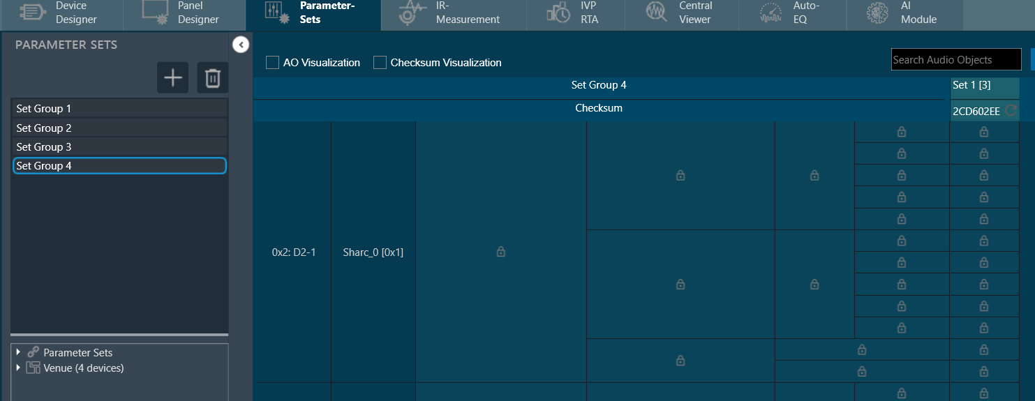
- In Parameter sets, Secure audio objects will be masked with the lock icon in the parameter sets window and presets cannot be changed.
- You can export .set and .setr files from presets and import it back. There will be no change in .set files. However secure audio objects will be excluded in .setr file as it is human readable. You cannot read the tuning data of secure audio objects in .setr files.
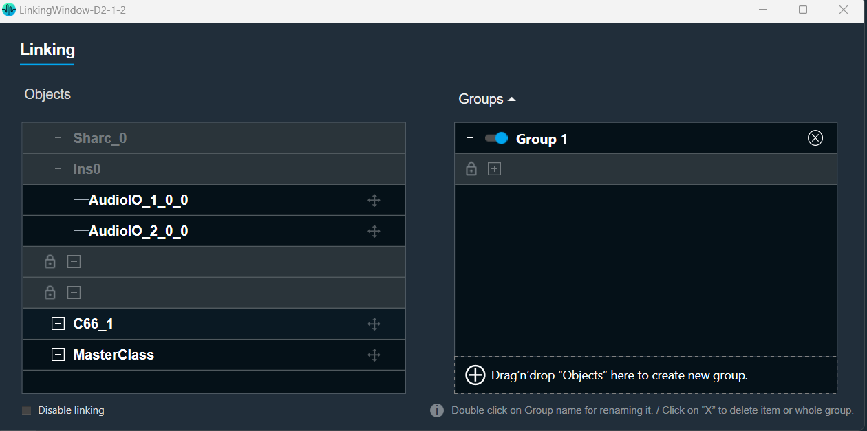
- If the audio object is locked, the secured audio objects will be masked with lock icon in linking window.
After locking the audio object it will be not be possible to add the secure audio objects for linking. The linking continues to function as intended.
- When you lock audio objects in a project, remember to also export the secure DLL before sharing the project with others. This DLL is required to use the locked audio objects.
On export of a project with secure audio object, a warning message will be displayed to export the secure dll from device designer.

- In the device designer, you can create a Xaf framework dll with the secure audio object information added to it.

- Exporting a secure DLL creates a copy of the specific audio framework version used in the project. This ensures compatibility between the project and the DLL.
A project containing secure audio objects can only be imported if the corresponding secure DLL is available. This DLL provides the necessary security measures to access and use the locked audio objects.
If the project creator doesn’t export the secure DLL, the other user importing the project might need a password. This password would be required to unlock and use the secure audio objects.
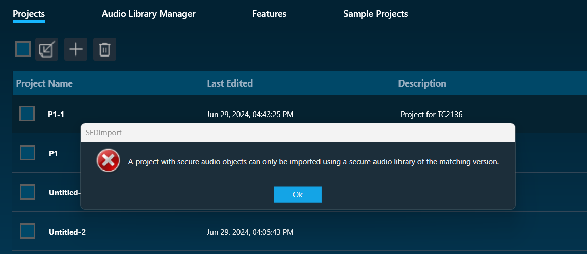
Attempting to import a secure project with an incompatible or unsecured DLL will result in an error message. This message likely informs the other user that the project requires a specific secure DLL for proper functionality.
- The secure dll is same as any other Xaf dll. It can be used for Integrated Virtual Processing (IVP). Also, all file properties of the dll will be retained.
- During project export and import, all audio objects will retain their secure status, including any passwords set on them. When the project is closed or opened, it retains its secure status.
When exporting the project with secure DLLs, it is mandatory to export the secure DLL. If not, the user has to share the password with other user who wants to use the project.
CAO type cannot be secured in W release