Loudness Operation
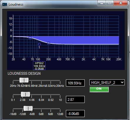
The purpose of the Loudness stage is to attenuate high frequencies as system volume is lowered. Loudness is implemented as a tone control filter object, which uses biquad filters with external gain control from the Control Interface. A custom panel for designing the loudness curve filter during design time, shown below, is provided with the project.
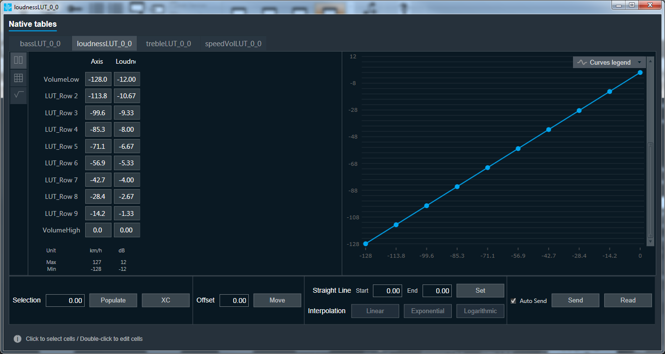
During system runtime, the gains of the filter are set by the “Loudness” column values in the look-up table loudnessLUT shown below. The “Axis” column shows values from the volume control. The two columns are mapped together, with the X axis being the volume control values and the Y axis being the resulting loudness gain values, to produce the curve shown on the right side of the look-up table panel.
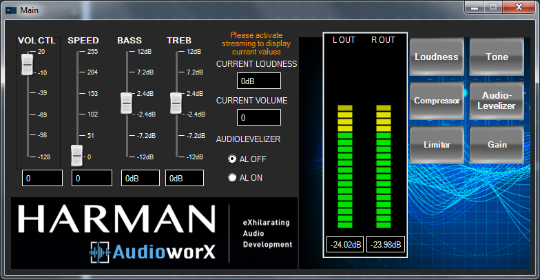
A typical loudness design workflow will alternate between the filter design and runtime testing using the look-up table and volume control. Convenient access to the volume control is provided via the Main custom panel shown below.
Note that while using the design panel when connected to a target device in real-time, changes in the loudness filter tuning will be sent to the target. However, the gain of the filter will be overwritten upon any volume control messages coming from the Control Interface
The filter gain should be set to 0 prior to saving the GTTD; otherwise the filter state may be out of sync with the volume control setting
Tone Control Operation
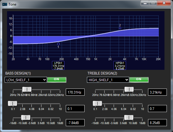
The purpose of the Tone Control stage is to provide bass and treble filters, the gain of which are set by external user controls in the Control Interface. Tone control is implemented with two biquad filters, one each for bass and treble. A custom panel for designing the tone control curve filters during design time, shown below, is provided with the project.
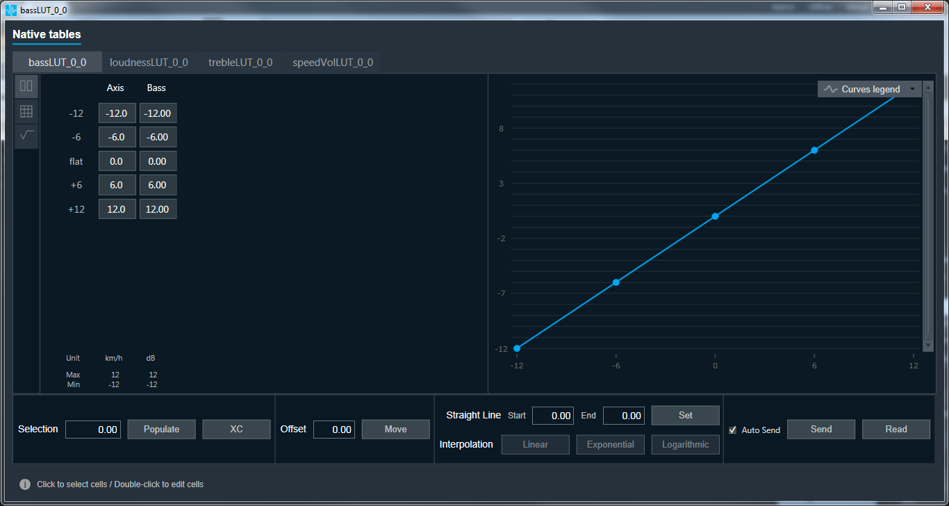
During system runtime, the gains of the filters are set by the values in the look-up tables lutBass hand lutTreble. The “Axis” column shows values from the bass control or treble control, sent by the Control Interface object. The two columns are mapped together, with the X axis being the tone control values and the Y axis being the resulting tone filter gain values, to produce the curve shown on the right side of the look-up table panel.
A typical tone control design workflow will alternate between the filter design and runtime testing using the look-up tables and tone controls. Convenient access to the volume control is provided via the Main custom panel.
Note that while using the design panel when connected to a target device in real-time, changes in the tone control filter tuning will be sent to the target. However, the gain of the filters will be overwritten by any tone control messages coming from the Control Interface
The filter gains should be set to 0 prior to saving the GTTD; otherwise the filter states may be out of sync with the tone control settings
Volume Operation
The purpose of the Volume object is to provide system gain and attenuation to the signal depending on the value of an external user control from the Control Interface. In the Basic reference project, an speed-controlled volume function is also implemented.
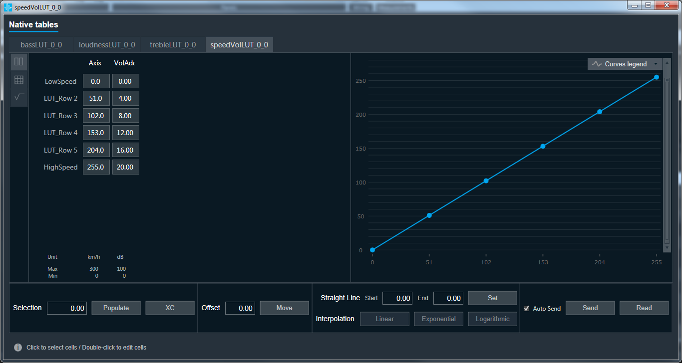
During system runtime, volume messages are sent from the Control Interface object to a control adder object that combines the volume control value with values coming from the look-up table lutSPEED. This look-up table converts the speed control value to a positive amount, which is then added to the volume control. In this way, an increase in speed will also produce an increase the volume control value sent to the Volume object. The amount set in the look-up table equates to a +20 volume value increase at maximum speed. The speed table is shown below.