FIR MIMO is a group of FIR filter banks associated with each input and output. They produce the preferred output signal to the speakers inside a vehicle based on the input signals and the vehicle’s interior design. FIR MIMO can be used for clever impulse and frequency optimization or applications such as individual sound zones.
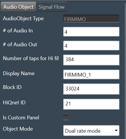
FIRA MIMO Properties
| Properties | Description |
| # of Audio In |
Enter the input value. Range: 1 to 20 The default value is set to 4. |
| # of Audio Out |
Enter the output value. Range: 1 to 64 The default value is set to 4. |
| Number of taps for Hi filters |
The number of filter coefficients (taps) for the high rate path is configured using the m_NumElements. All channels in the high rate path use the same number of taps. Range: 384 to 4096 The default value is set to 384. |
| Display Name | Display name of the FIRMIMO audio object in signal flow design. It can be changed based on the intended usage of the object. |
Mode
The FIR MIMO audio object supports two modes of operation.
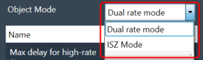
- Dual Rate mode
- ISZ mode
Dual Rate mode: In the GTT interface, you can select the number of filter taps and filter combinations. The default (and minimum) number of taps for the high rate filters is set to 384.
ISZ mode: In the ISZ mode, the object acts as a single rate (high rate) FIR MIMO object for accomplishing ISZ (Individual Sound Zones). For ISZ, the low rate path of FIR MIMO block is disabled, and the high rate path delay is fixed to zero.
In addition, all the filter combinations are active by default for ISZ mode. You do not need to individually configure the additional configuration matrix to set the filter in each combination. Even though the m_AdditionalConfig parameters do not indicate that all the filters are active, the active filters can be viewed when we open the tuning panel for this object.
The filter tap length should is fixed to 4096 only. This size must be fixed by you each time you switch to ISZ mode. This will be changed in future; where filter taps will be directly fixed by GTT when ISZ mode is selected. The max delay for hi rate filters will also be set to 0 only.
These filters are designed using a highly specialized tuning algorithm, known as MFxLMS (Multiple Filtered Input Signal Least Mean square). Several constraints such as pre-ringing and post-ringing, frequency and phase constraints are applied to allow the CTC filter networks to be realizable with FIR taps to provide the desired response.
There are two stages in the ISZ algorithm:
- Design: At design time, the transfer function between each individual speaker and a microphone array placed at the listener’s head (i.e. for each zone) is measured. These transfer functions are used to feed the MFxLMS algorithm, which runs and simulates audio throughput until an optimal solution is found to generate the desired zone isolation.
- Playback: The resulting FIR coefficients calculated by the MFxLMS process are then applied to the playback algorithm, which is the MIMO system formed by high rate path of FIR MIMO. All speakers are always contributing to each path; i.e. every speaker is used at all times to achieve the ISZ effect regardless of which zones are bright or dark.
Additional Parameters
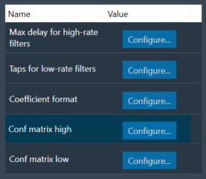
Below table describes the FIR MIMO additional parameters.
| Parameter | Description | |
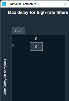
| Max delay for high-rate filters |
Length of delay line for high-rate path. Range: 0 to 2048 Default: 0 Data Type: uint32_t |
 |
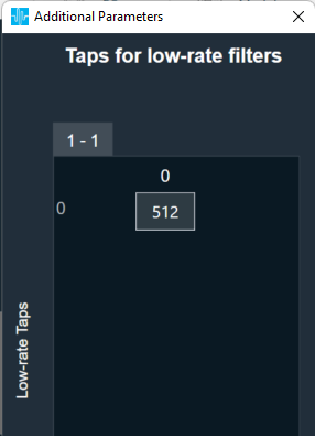
| Taps for low-rate filters |
Number of taps for low-rate filters. All channels in the low rate path use the same number of taps which can be different from high rate. Range: 512 to 2048 Default: 512 Data Type: uint32_t |
 |
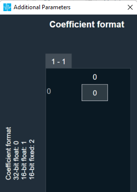
| Coefficient format | Filter coefficient data format.
Range: 0 to 2 Default: 0 Data Type: uint8_t |
 |
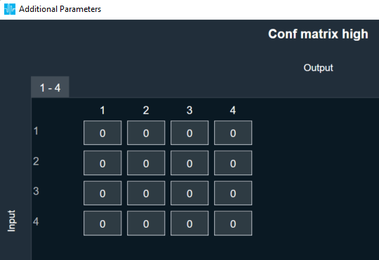
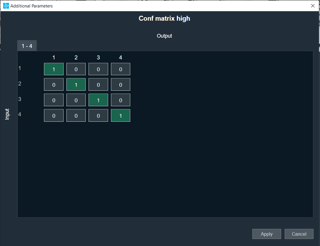
| Conf matrix high | Configuration matrix for high rate filters.
Value:
Range: 0 to 1 Default: 0 Data Type: uint8_t |
 |
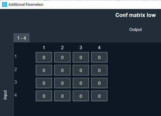
| Conf matrix low | Configuration matrix for low rate filters.
Value:
Range: 0 to 1 Default: 0 Data Type: uint8_t |
 |
Tuning Parameters
For each filter combination in FIR MIMO, this object exposes these two tuning parameters to the GTT:
- Mode – The parameter is of the category “State” and therefore, the configurations done for Filter modes will be transferred to device only after device is connected. The mode of each filter can be set to:
- Active
- Bypass
- Off
- Coefficients – Filter coefficients can be imported from .csv files. The filter taps set in the GTT must
match the taps of the filter being imported from the .csv file.
Control Parameters
There are no control inputs.
Native Panel
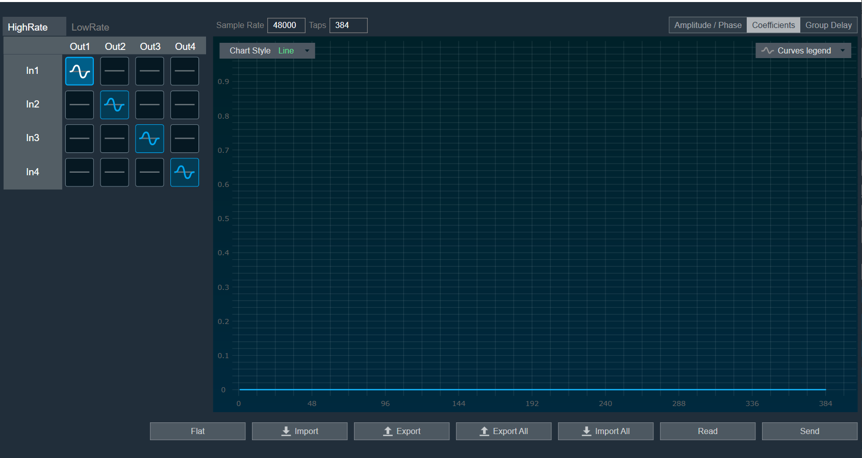
FIR MIMO native panel allows you to configure the Mode of each enabled filter and to load coefficients as well. All the diagonal filters are active as this diagonal values are configured through additional parameters. In order to see the graphs, you need to import coefficients. Use ‘Import’ or ‘Import All’ option to import coefficients.
To open the native panel, double-click on the FIR MIMO audio object in the signal flow designer.
When the device is connected the filter states will not be in sync with the device until the states are received or the native panel is opened. Once the native panel is opened after a successful connection, the filter states will be transferred to the device.
Provide number of Taps to 384 and from additional parameters set all diagonal cell to 1 for Conf matrix high/ low as per below image.
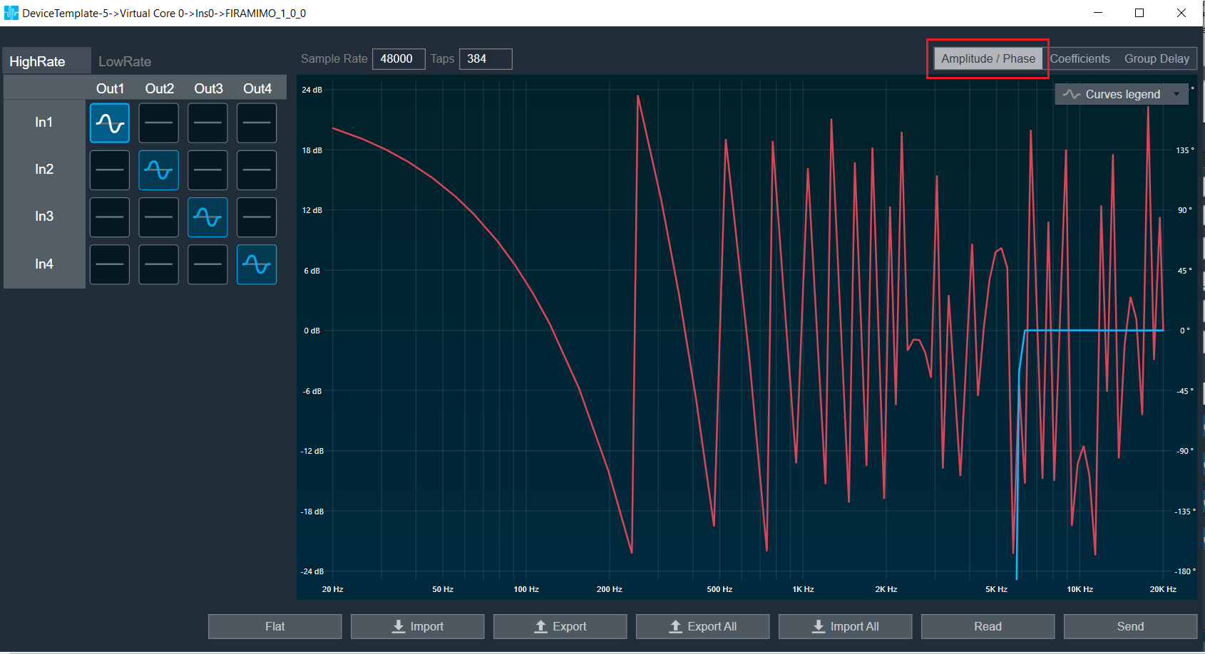
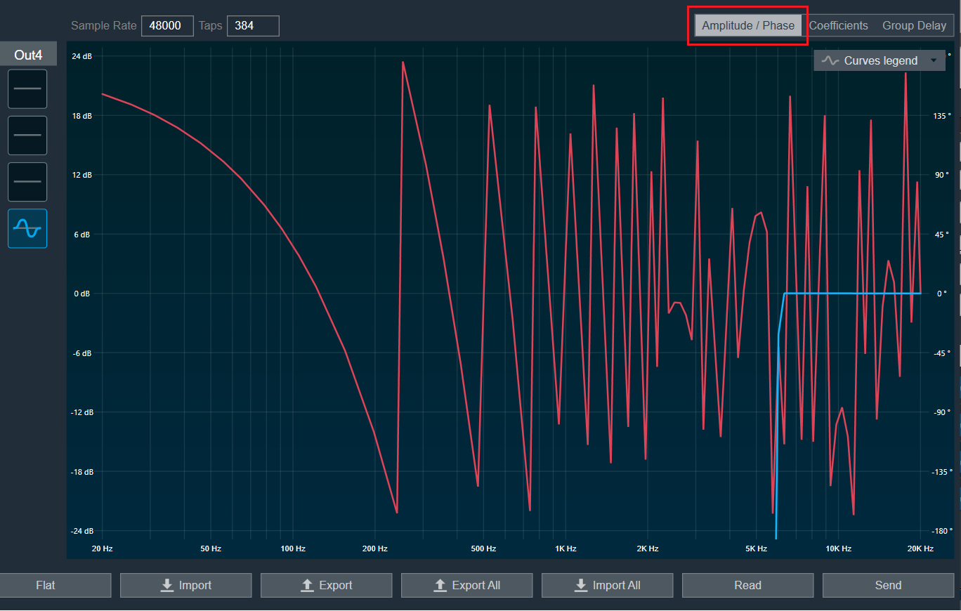
Amplitude/Phase: When the coefficients are given and “Amplitude/Phase” option is selected, the graph display the value as per below figure.
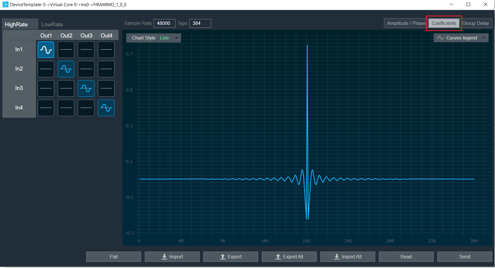
Coefficients: When the coefficients are given and “Coefficients” option is selected, the graph display the values as per below figure. You can change the graph style using “Chart Style” option.
- Line chart style: when “Chart Style” selected as Line, the Coefficients graph as per below image.
- Dot chart style: when “Chart Style” selected as Dot, the Coefficients graph as per below image.

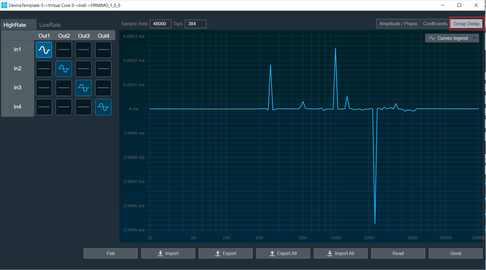
Group Delay: When the coefficients are given and “Group Delay” option is selected, the graph display the values as per below figure.
Curves Legend: This option allows you to show the details of which graph tab (Amplitude/Phase, Coefficients, Group Delay) is selected.
On the selection of Amplitude/Phase graph tab Curves Legend will show below information.

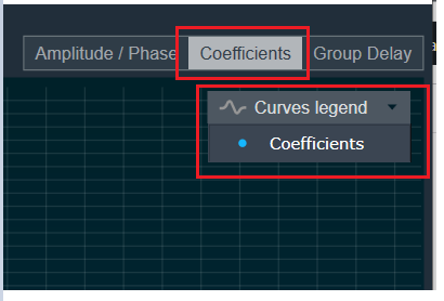
On the selection of Coefficients graph tab and Chart Styles ‘Dots’, Curves Legend will show below information.
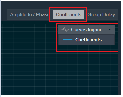
On the selection of Coefficients graph tab and Chart Styles ‘Line’, Curves Legend will show below information.
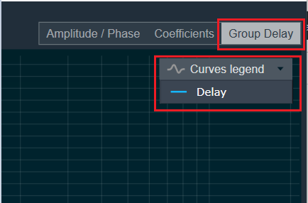
On the selection of Group Delay graph tab, Curves Legend will show below information.
Additional Functionalities
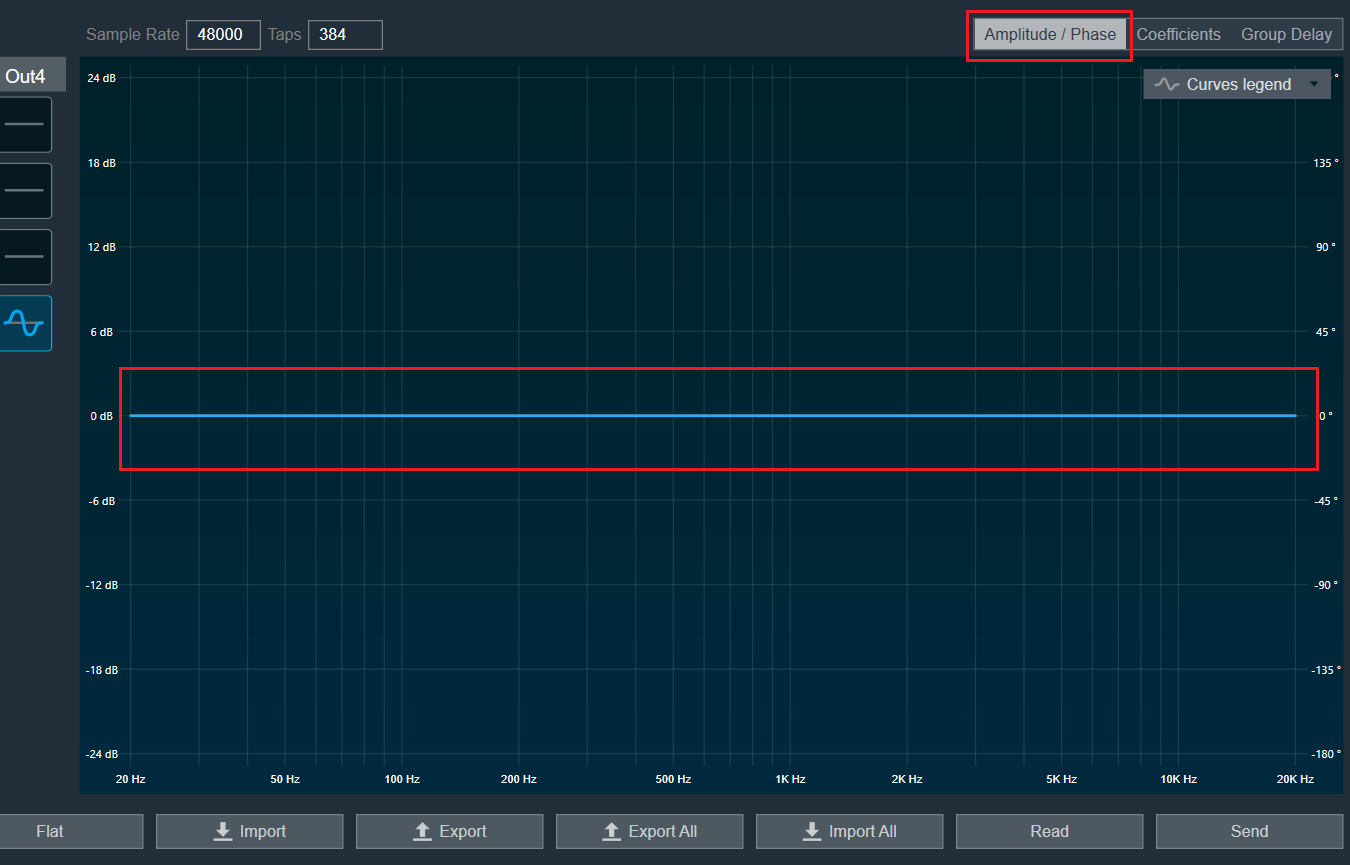
Flat : This is used to make the graph flat by making coefficients to 0.
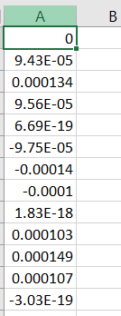
Import : This function is used to import the coefficients for a single active filter. Click the “Import” button, then enter the file path and click Ok.
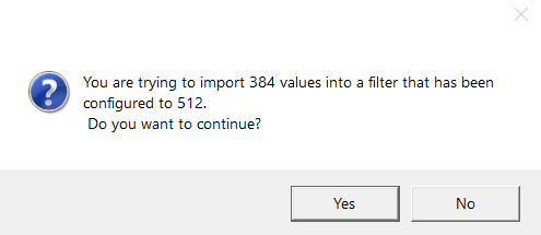
All coefficients for the selected filter will be imported, as shown in the graph. If the number of coefficients does not match the number of taps as shown in the screenshot below, a warning pop up will appear.
Click ‘Yes’ to import available coefficients or click ‘No’ to cancel the import.
Export : This option is used to export coefficients for selected active filter into csv file.
Export All : This option is used to export all active filters in one go. Click the “Export All” button, then enter the path and file name, then click Ok.
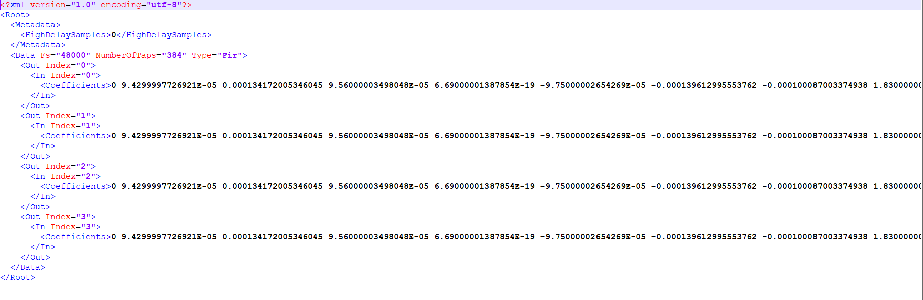
A xml file will be created which will have coefficients for each active filter. Below figure shows the example of the configuration of the active filters in the xml file.
You can use Import All’ button to import back the exported file.
Import All : This option is used to import all coefficients in one go. Click the “Import All” button, then enter the XML file path and click Ok.
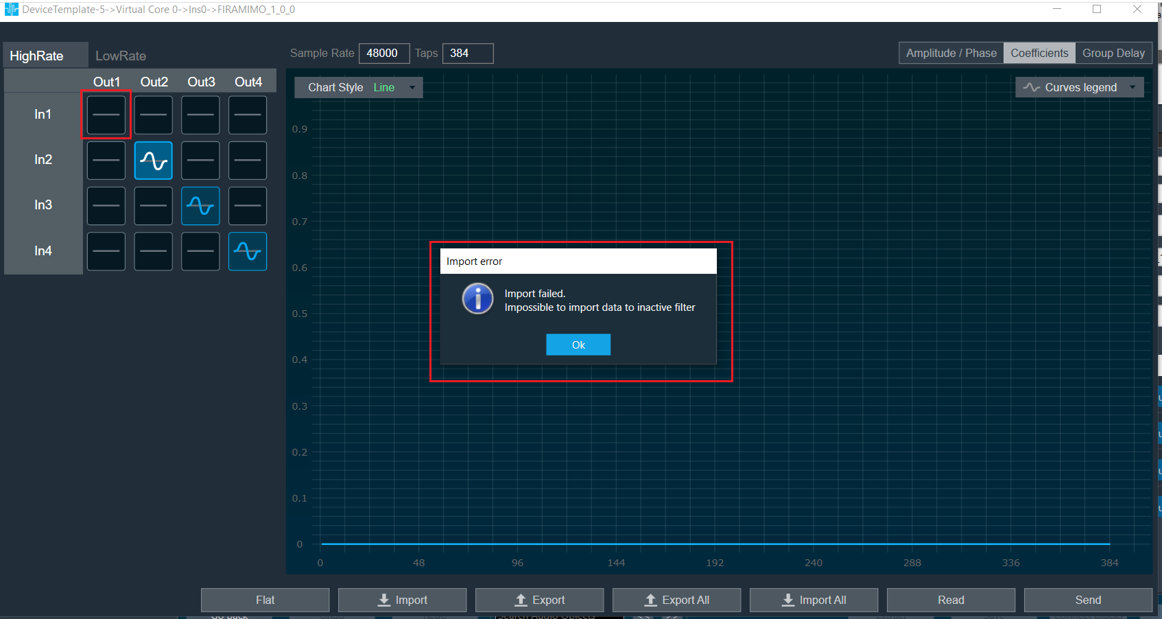
All the given coefficients will be imported and can be seen in the graph. If there is a mismatch between xml file In and Out matrix with FIRMIMO panel In and Out matrix then error will be displayed and import will fail.
In below image filter (Out 1 In1) is not active and try to import this as well so error is prompted.
Read: This is used to read from the target to display in the panel.
Send : This is used to send the values changed in panel to target.
Above mentioned functionality is similar for LowRate tab as well.
Memory allocation for optimized MCPS on SHARC Platform
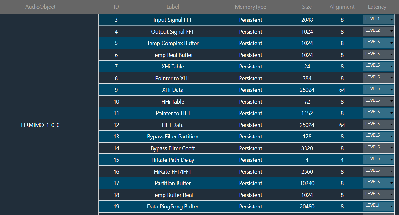
The FIRMIMO audio object has memory records for FFT of input and output signals and scratch memory record used for Ping Pong Buffers for data and coefficients (SHARC platform) and temporary buffers for upsampler/downsampler. The MCPS performance depends on allocation of these buffers to lower memory latency levels.
- For FIRMIMO memory latency is pre-allocated in code for certain memory records in SHARC platform.
- For memory record for FFT of input buffers (memory record label: Input Signal FFT), Level1 is assigned.
- For memory record for FFT of output buffers (memory record label: Output Signal FFT), Level2 is assigned.
Level 1 latency is assigned to Ping Pong Buffers for Data (memory record label: Data PingPong Buffer) and Scratch Memory Record.
MCPS Constraints
Firmimo consumes more mcps for smaller block lengths when filters used is higher tap size. Higher block lengths has better MCPS performance. It is suggested to check mcps before finalizing the design.