
1.Terms and Abbreviations
| Abbreviation | Meaning |
| EOC | Engine Order Cancelation |
| AO | Audio Object |
| GTT | Global Tuning Tool |
| HAL | Harman Audio Library |
| VST | Visual Studio Technology |
| xAF | Extendable Audio Framework |
2.Purpose of the Document
EOC is a tool used for reducing engine noise. GTT is a customized branch of AudioArchitect from Harman’s Professional Division and EOC is a Harman IP Algorithm Object available in the Audio Algorithm Toolboox and supported by GTT. This user guide will give you an overview of the use cases of EOC in GTT. For general information on how to use GTT, please refer to the Global Tuning Tool User Guide.
3.Overview of the System
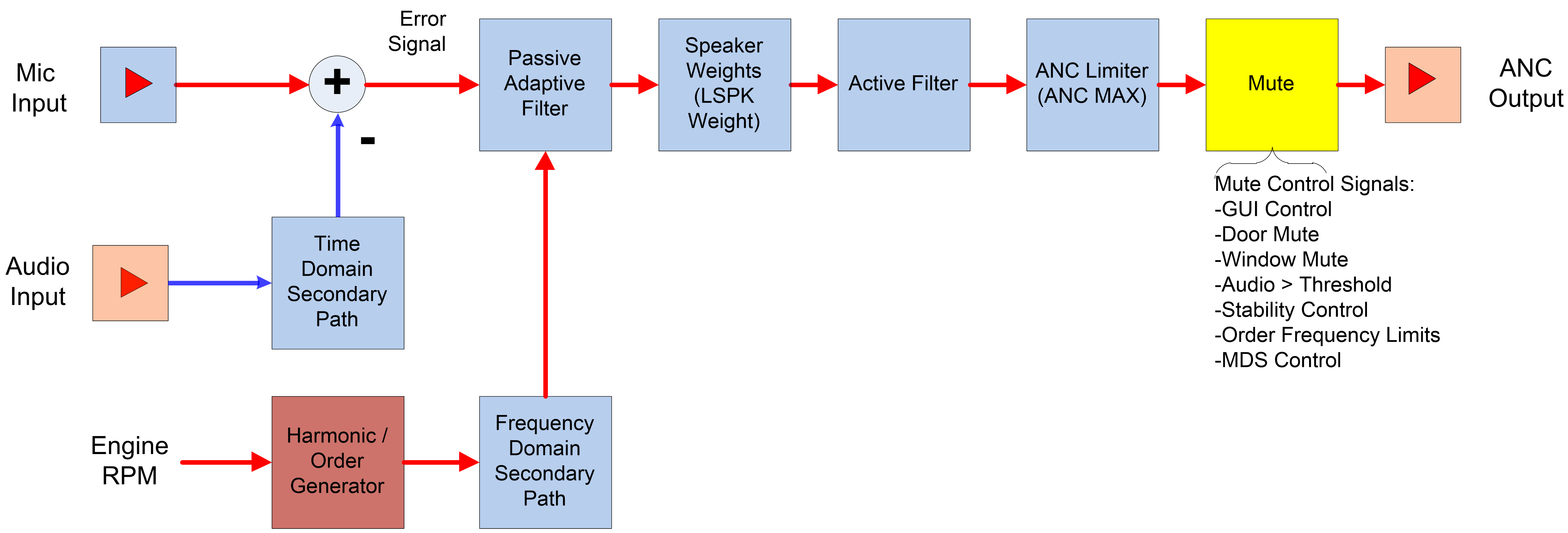
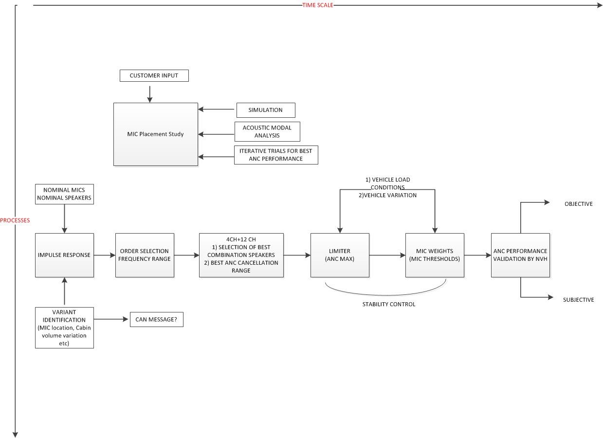
4.Overview of EOC Tuning Process
Tuning process overview below represents a high level block diagram of the EOC Tuning Process.
5.Setting-Up the hardware bench
Hardware required:
- Power supply.
- USB cable with an integrated RS232 FTDI chip.
- Amplifier wiring harness.
- Laptop/PC with a Windows 7 x64.
Set-up Steps:
- Connect wiring harness to the amplifier.
- Connect the other harness end to power supply (GND cable -> GND, BAT cable, Amp Enable -> VCC)
- Connect the USB cable to the amplifier and to the USB port.
A new com device should appear in the device manager. If this is not the case please install the latest FTDI drivers.
6.Running AmpSrv2
If you want to connect to a target device you have to start AmpSrv2 before a device is placed on the venue of Global Tuning Tool. AmpSrv2 is a software that is used to connect the tuning tool to either a physical target device or a virtual amplifier.
7.Settings
Open “AmpSrv2” from start menu (installed along with GTT tool).
Ampsrv2 drop down should have Message(socket) selected.
Some configuration should be done to make sure to get this link running well.First select “File” then “Options”.

In general tab, ensure the “Serverport” is 24576.

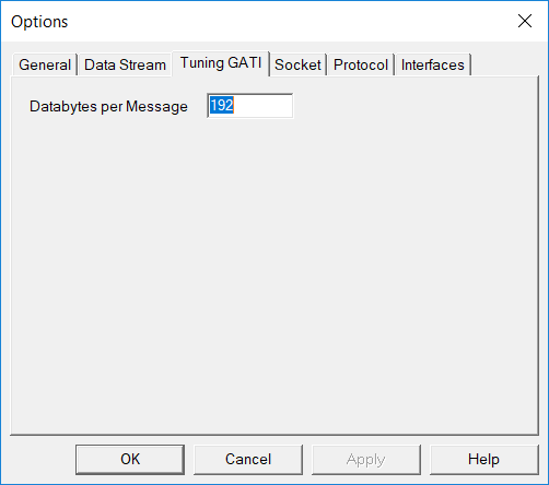
In “Tuning GATI” tab, set “Databytes per Message” cell to 192.
In “Socket” tab, be sure to set “Port” to 25001 and “Protocol” to GATI.

Click “OK” to save changes.
8.Debugging
Not all functions of AmpSrv2 are available to every user. AmpSrv2 is shipped with a limited license called “Customer.lic”. If a functionality is grayed out (not available), it is probably because you have a limited license. For activating a new license check “UserGuideAmpSrv2”.

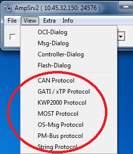
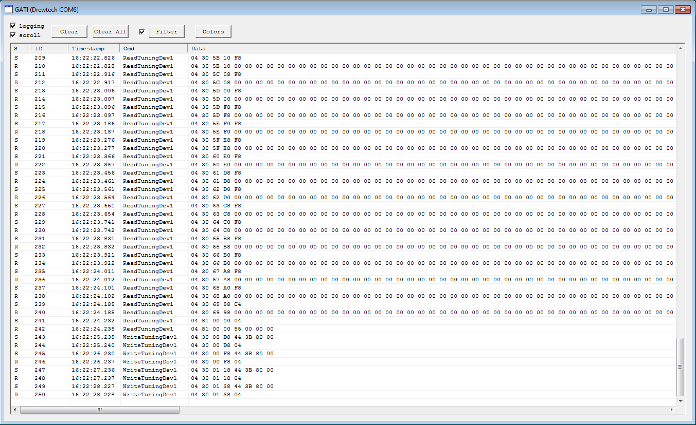
If you want to see the messages sent / received by GTT you can open the GATI / xTP protocol window of AmpSrv2.
Menu: View -> GATI protocol
9.Running EOC window from GTT
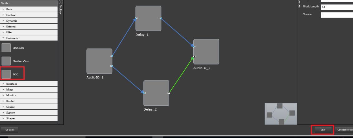
To run EOC user must open the signal flow designer for a device (by double-clicking the device), add the Halosonic -> EOC block to the SFD, save the pipeline, double click on the EOC block.
10.EOC
Tuning Data
In EOC tool user can save and read tuning data from XML file.
Open
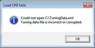
Opens saved tuning data from file and sends loaded data to DSP RAM. During opening the file is checked basic validation of XML. If the XML file is corrupted, user will be informed about that.
Save
Saves actual tuning data on disc C:\ in file TuningData.xml.
Save As
Saves actual tuning data in the XML file given by the user.
Read Set
Read all data from DSP RAM into the tuning tool and updates the UI controls.
Import IR Data
Import impulse response data from two files for time (TimeDomainData) and frequency (FrequencyDomainData).
Export IR Data
Export impulse response data into two files for time (TimeDomainData) and frequency (FrequencyDomainData).
11.System Controls
11.1.Flash Set (Save)
Writes the tuning parameters to flash memory on the DSP (non-volatile), so if the vehicle/amplifier is reset or goes through power cycle the parameters are still available.

11.2.Send to RAM
Sends all data to DSP RAM.
11.3.EOC OFF
- Turn ON / Turn OFF – Turn the eoc functionality on, turn the eoc functionality off.
- EOC ON – EOC is on
- EOC OFF – EOC is off
11.4.Music COMP OFF
- Turn ON / Turn OFF Music COMP
- Turn True Audio (a.k.a. Music Compensation on), Turn True Audio off.MUSIC COMP ON
- Music COMP is onMUSIC COMP OFF
- Music COMP is off
11.5.STAB OFF
- Turn ON / Turn OFF STAB – Turn Stability control algorithm on, Turn Stability control algorithm off.
- STAB ON – STAB is on
- STAB OFF – STAB is off
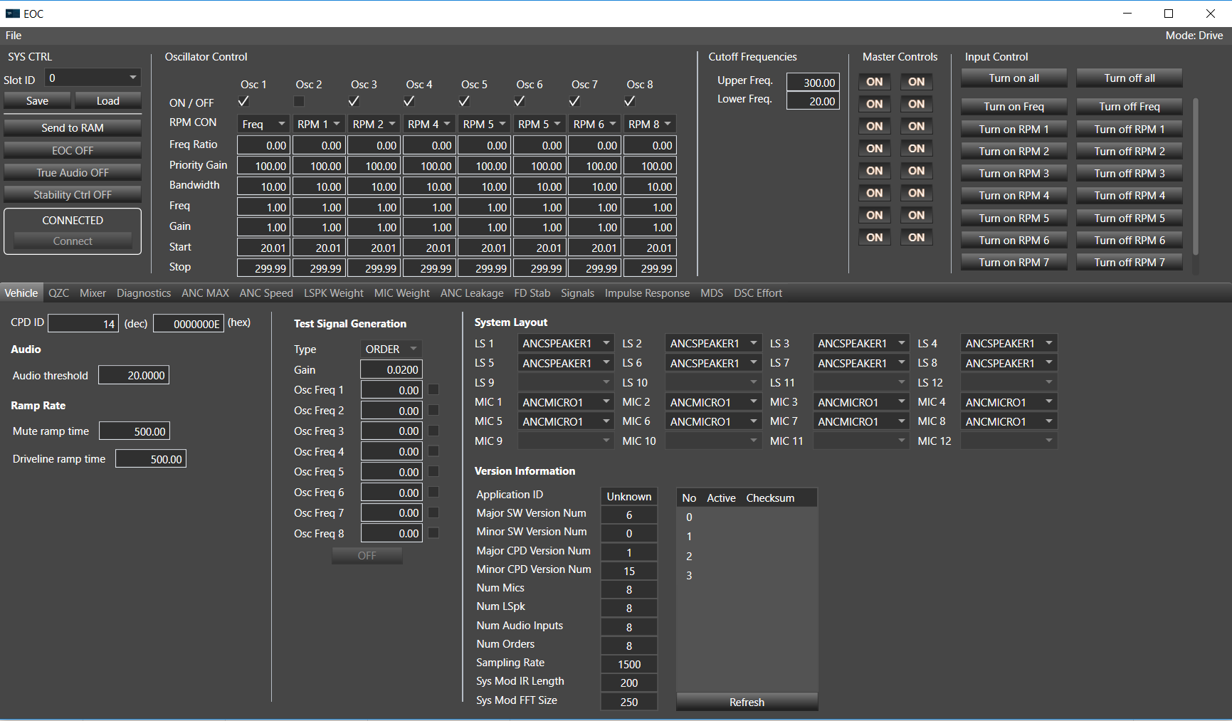
12.Oscillator Control
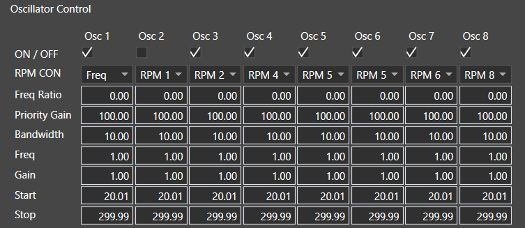
In this section user can change oscillator settings.
Each Oscillator on the Main tab is capable of generating a continuous sine wave signal either at the desired (fixed) frequency or at frequency corresponding to the reference signal (RPM signal), when the respective RPM CON is checked for that oscillator. In order to set up a single oscillator, start with the OSC1 always, if OSC1 is left blank and OSC2 is set up, there will be no ANC output.
- ON / OFF – inform if oscillator is on or off
- RPM CON – if this check box is checked, frequency is calculated from the RPM, otherwise frequency is get from the text box Freq.
- Freq Ratio – Specifies the Engine Order to cancel. Cancellation frequency = Freq. Ratio * RPM/60
- Priority Gain – standard edit box where user can set values from 0 – 100 for every oscillator.
- Bandwidth – Bandwidth of the tracking filter, typically, only 5Hz is supported.
- Freq – value of frequency
- Gain – value of gain
- Start and Stop – defines frequency sub range where EOC is disabled
Number of oscillators is always the same as number of orders which means the number of RPM drop-down controls (RPM CON) viewed in EOC panel depends on the number of orders (1-8).
RPM Con is the functionality to choose the input to calculate frequency from RPM.
When on the drop-down button is selected:
- Freq – frequency is get from the text box Freq
- RPM 1 – frequency is calculated from 1st RPM control input
- RPM 2 – frequency is calculated from 2nd RPM control input
- RPM 3 – frequency is calculated from 3rd RPM control input
- RPM 4 – frequency is calculated from 4th RPM control input
- RPM 5 – frequency is calculated from 5th RPM control input
- RPM 6 – frequency is calculated from 6th RPM control input
- RPM 7 – frequency is calculated from 7th RPM control input
- RPM 8 – frequency is calculated from 8th RPM control input
For Drive object mode, the number of values viewed on each RPM Con drop-down control depends on the number of RPM inputs.
For Normal object mode, each RPM Con drop-down control always contains two elements, “Freq” and “RPM 1”.
13.Cutoff Frequencies
Global setting for Start and Stop in oscillator control. Defines frequency sub range where EOC is disabled.

14.Master Controls
There are logical microphones and logical speakers which you can turn on and turn off. Count of microphones and speakers is set in DDF. Master controls settings is coupled with System Layout. When you turn off first microphone in System Layout first microphone will be set on NOMIC. When you turn on in master control Mic 1 then in System Layout first microphone will be set on value which was set before. Turn on and turn off speakers behaves similar like microphones.
- NOMIC value is 4294967295
- NOSPK value is 4294967295
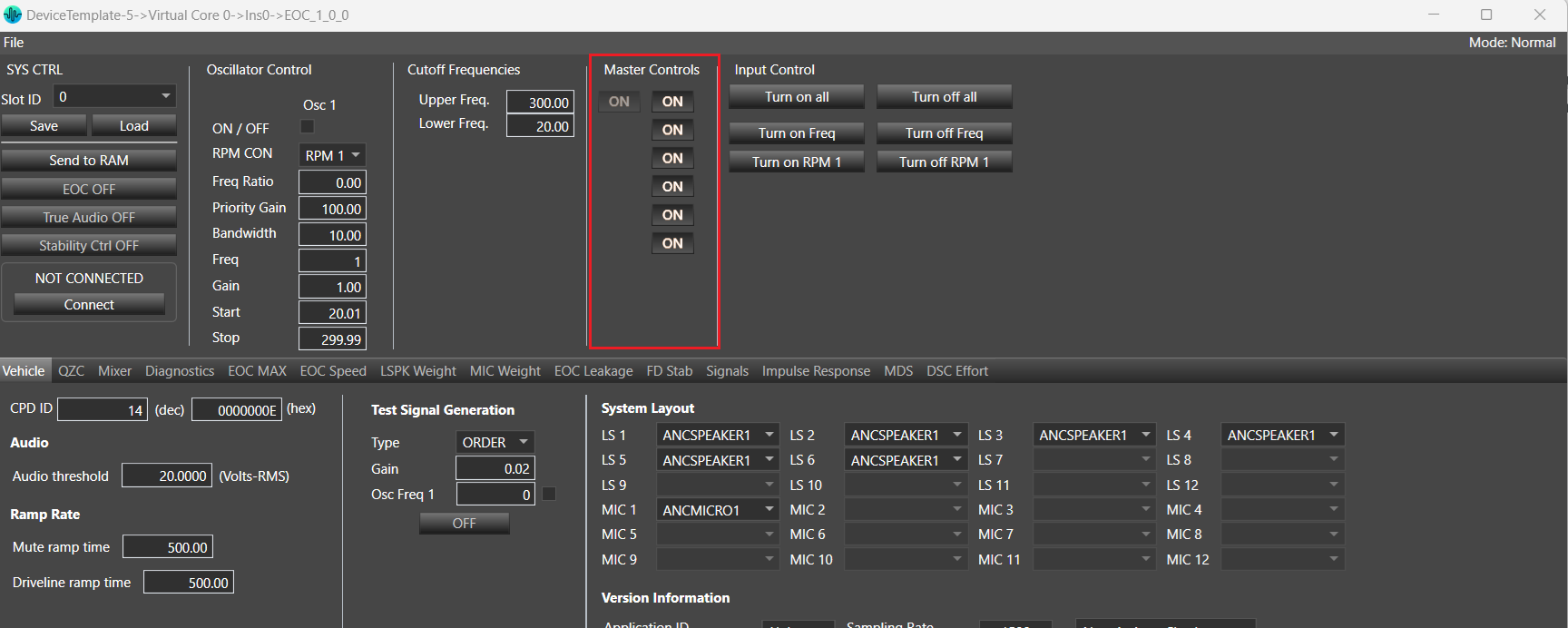
At least one microphone and one speaker must be selected. Validation rules will prevent user from switching of all microphones or speakers.
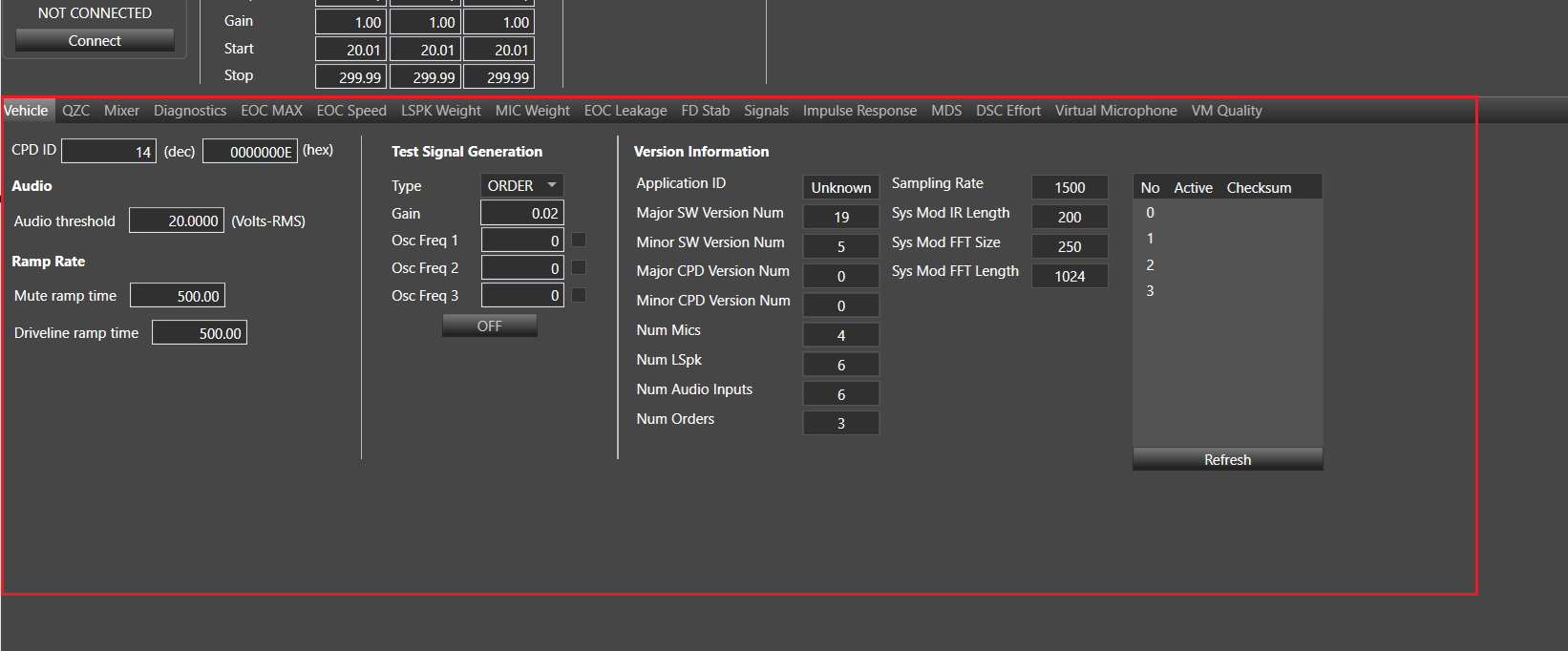
Master Control section will not be visible if VM Config option is available in Additional parameter section.
If below VM Config (Virtual Mic Enable) option is available.
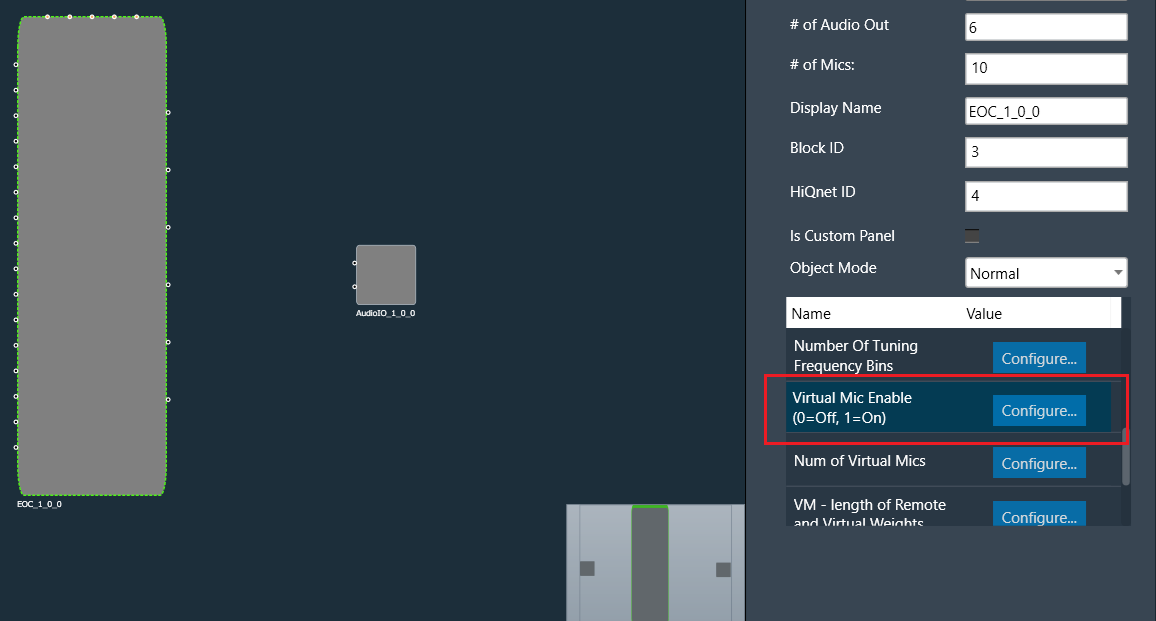
If VM config is available then Master Control section will not be visible as per below screen shot.
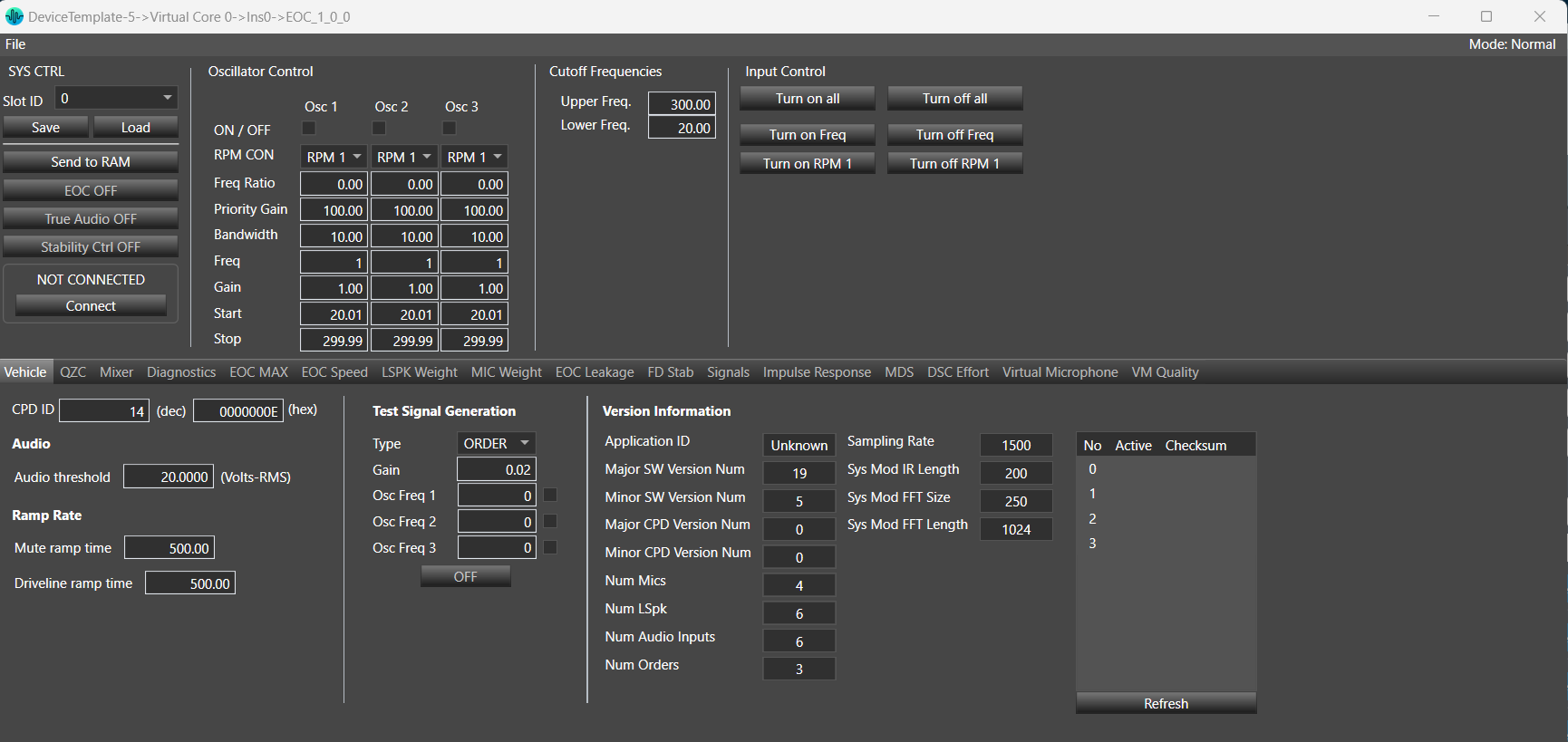
15.Vehicle
In this tab contains information and configuration option about the vehicle.
System Layout section will not be visible if VM Config option is available in Additional parameter section.
If below VM Config(Virtual Mic Enable) option is available.
If this is available then Vehicle tab will look like as per below screen shot.
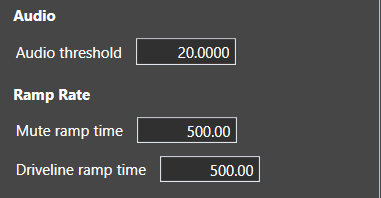
15.1.Audio and Ramp Rate Sections
Audio threshold enable to set how big is the threshold for audio output with units from 0 to 35
Mute ramp time is a delay time for increasing volume of sound when you are starting or stopping generate audio, determined in milliseconds with the range from 1ms to 6000ms.
Driveline Ramp Rate is used for dealing with conflict between orders (Overlapping problem). Determined in milliseconds with the range from 1ms to 1000ms. If the frequencies of any oscillators are within the frequency limit, then apply the priority gain to the oscillator. Smoothing will also need to be added. When expanding this to multiple orders, it might be faster to search for non-unity gain factors 1st, and then check if there is a frequency overlap condition with another order. Chances are the tuning will have a majority of the gain factors set to 1.0, most orders will be linked to common RPM sources and won’t overlap.
15.2.Window Position Threshold
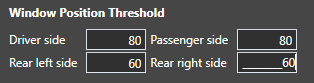
Window Position Threshold section is available for devices which supports this functionality.
This section allows setting window position threshold for driver, passenger and rear windows.
These settings accept values from 0 to 100.
15.3.Doors dependency

Doors dependency section is available for devices which supports this functionality.
This section allows to enter the following settings
| Name | Description |
| DRV_AJAR |
Flag to indicate whether the Driver side door is open or not |
| PSG_AJAR | Flag to indicate whether the Passenger side door is open or not |
| L_R_AJAR | Flag to indicate whether the Left Rear side door is open or not |
| R_R_AJAR | Flag to indicate whether the Right Rear side door is open or not |
| FG_AJAR | Flag to indicate whether the Flip glass open or not |
| TLG_AJAR | Flag to indicate whether the Lift Gate open or not |
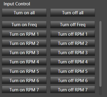
16.Input Control
Turn off all and Turn on all – those buttons are responsible for turning on/off all oscillator. There is no meaning which RPM is selected.
Turn off RPM X / on RPM X (where X is number of RPM CON element) – those buttons have two functionalities:
After clicking on button “Turn on RPM 1”, all oscillators with RPM 1, will be set to ON.
After clicking on button “Turn off RPM 1”, all oscillators with RPM 1, will be set to OFF.
Above operations works similarly for all “Turn on RPM …” and “Turn off RPM …” buttons depending on selected RPM number.
After clicking on button “Turn on RPM 1” while pressing Ctrl key, all oscillators with RPM 1,will be set to ON and all oscillators with RPM number different than 1 will be set to OFF.
Above operations works similarly for all “Turn on RPM …” and “Turn off RPM …” buttons depending on selected RPM number.
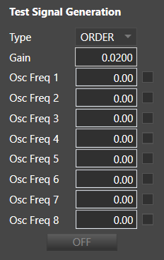
17.Test Signal Generation
Test signal generation function is used as a quick test of the system: GUI/DSP/amplifier/speaker. Before starting the EOC tuning process, use this feature to verify the system.
- TYPE (ORDER, RNOISE) – Order selects sinusoidal test tone. Other types (RNOISE) available depending on amplifier product.
- Gain – test signal gain
- Osc Freq 1, 2, 3, 4, …, 8 – after setting value, mark check box value and turn on test signal generation values of frequency will be set in Oscillator Control. For oscillators which are not selected, On/Off status and frequency will be not updated in Oscillator Control.
- Checkboxes indicate for which oscillators the test signal should be applied, not the status of the oscillator.
- Turn off test signal will set previous values in Oscillator Control.
- Changing On/Off status in Oscillator Control will not affect values in Test Signal Generation control.
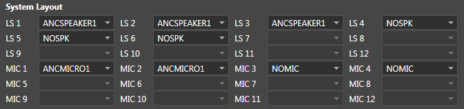
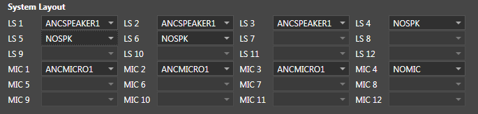
18.System Layout
In the System Layout, you can couple logic loudspeaker with physical loudspeaker and logic microphone with physical microphone. System layout are coupled with Master control where user can turn on and turn off microphones and loudspeakers.
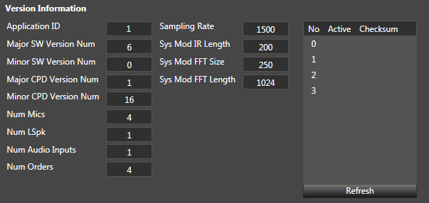
19.Version Information
In this section are information about the current amplifier software version and the amplifier parameters. Table on the right shows information about CPD slots on device.
20.QZC
Quiet Zone Control (QZC) is part of the EOC algorithm that allows modification of weighting between speaker and microphone relationships per cancellation engine order.

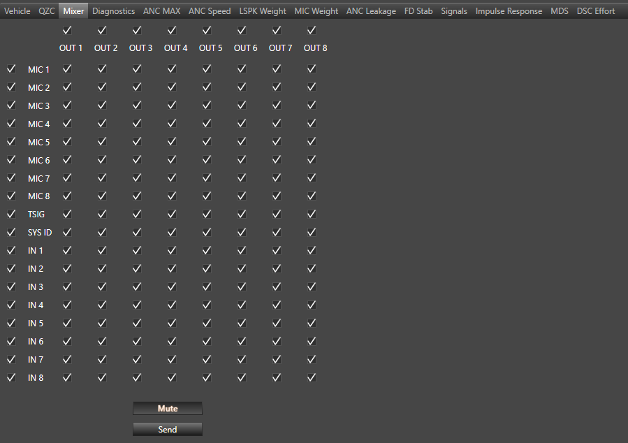
21.Mixer
This Mixter tab is used for making connections between the system inputs and outputs
- Mute – Will globally mute all outputs from the ANC mixer. If this is enabled, all outputs will be zero.
- Send – updates the amplifier mixer settings
- Checking the boxes on the left-hand column will enable the inputs to the mixer.
- Checking the boxes along the top of the mixer will enable those channel outputs from the mixer
The EOC mixer only allows one to one relationship between input and output for the audio channels, which means that the 1st input has to be matched with 1st output, 2nd input has to be matched with 2nd output, etc.
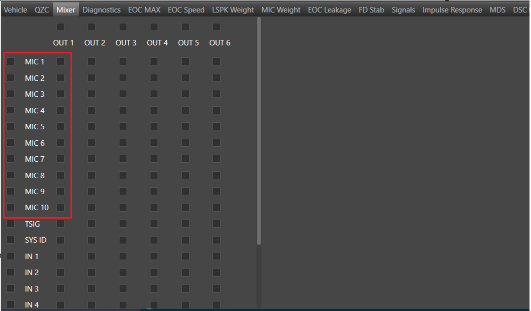
Number of Mics(Mic 1, Mic 2…) will be equal to the m_NumElement(‘# of Mics:’)
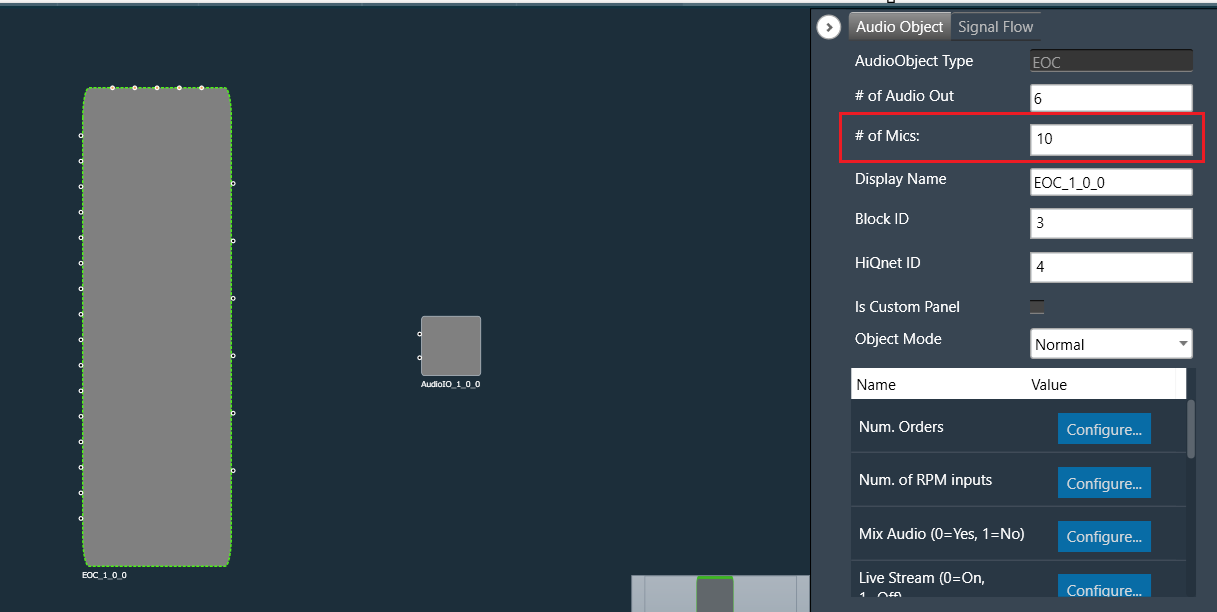
Below are the number of mics equal to the # of Mics.
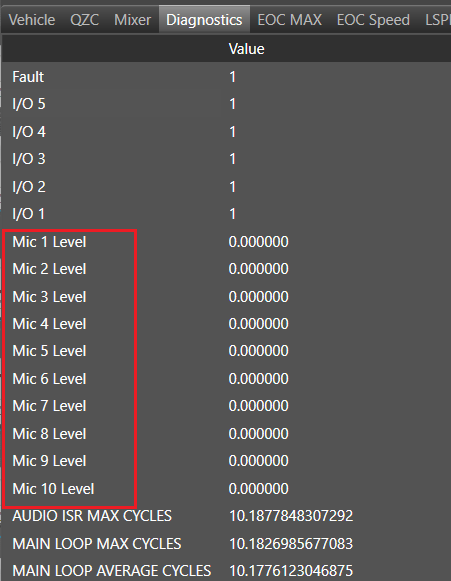
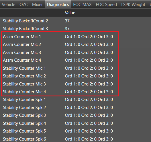
22.Diagnostics
The Diagnostics tab shows diagnostic parameters.

Make sure the number of microphones for mic levels in the Diagnostics tab is equal to m_NumElements(# of Mics:)
Make sure the number of microphones for ‘Assm Counter Mic’ and ‘Stability Counter Mic’ in the Diagnostics tab is equal to m_TuneMicNum. If Vm Config is disable then m_TuneMicNum is equal to m_NumElement(# of Mic:) and if Vm Config is enable then m_TuneMicNum is equal to Num of Virtual Mics(from Additional Parameter section).
Below are number of mics when Num of Virtual Mics =4.
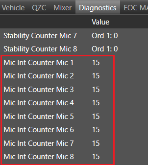
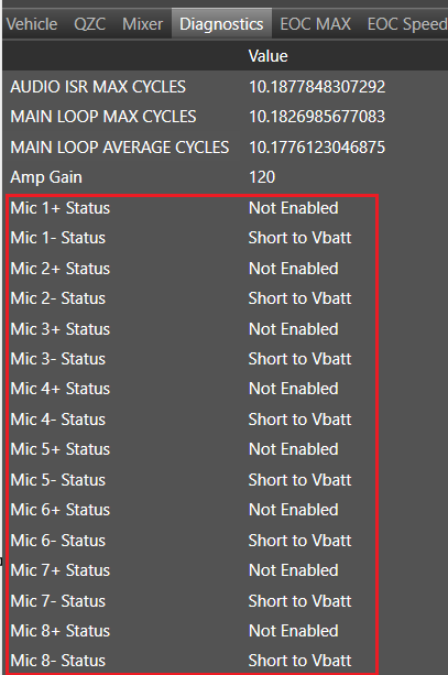
Section ‘Mic Int Counter Mic’ and ‘Mic Status’ will not be seen if VM Config is available.
Start Polling: Start refreshing diagnostic parameters (Interval polling time – 500ms).
Stop Polling: Stop refreshing diagnostic parameters.
Clear Diagnostics: Clear diagnostic parameters list.
Export: Exports diagnostics data to the *.csv file.
22.1.Control signals
RPMs
Diagnostics tab shows also information about value received from Control In pins for all of RPMs set in EOC. Assigning specific pins inside Control In can be done in Signal Flow Designer.

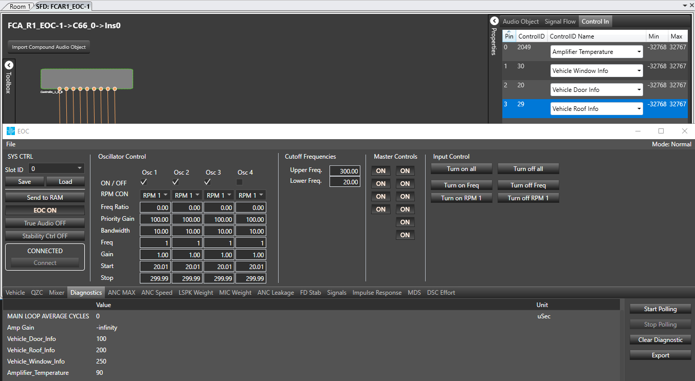
Other control signals
Diagnostics tab displays some control signals directly from Master Control. Those control signals are displayed without unit and any conversion of value.
Below table contains a list of control signals displayed directly from Master Control.
| Control ID | Control name |
| 2049 | Amplifier Temperature |
| 30 | Vehicle Window Info |
| 20 | Vehicle Door Info |
| 29 | Vehicle Roof Info |
To display above control signals in the diagnostics tab the user only need to add them to the Control In object in SFD.
23.ANC MAX
The signal level for each Engine order (set up for EOC in the vehicle) can be controlled for each loudspeaker, per frequency by adjusting the values in this tab. This value represents the EOC signal contribution coming from a particular speaker in a specific frequency range. In order to mute a particular speaker for a specific frequency range enter a value of “-120(dB)”. In order to utilize all the available signal gain from a speaker specific to a freq range, enter a value of “0(dB)”,
i.e. -120dB < ANC Max < 0dB.
Send – send data to DSP
Radio button list with oscillators gives a possibility to switch between data series which matches with each oscillator.
Import from Signals tab – Current order only – is responsible for importing ANCFilterABS data for one oscillator only (visible only if peak extension is available)
Import from Signals tab -All orders – is responsible for importing ANCFilterABS data for each oscillator (visible only if peak extension is available)
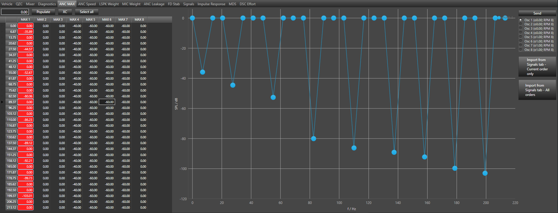
23.1.Using grid and graph
Using grid
- Changing each value separately in grid cell
- Populate – set all selected value to value from text box above grid.
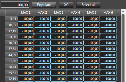
- XC – sets all values below current to current value
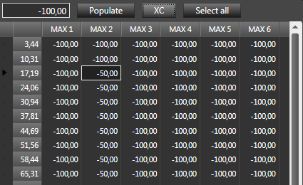
- Select all – select all cells
Using graph
- By marker – catch marker on the graph and move to right place
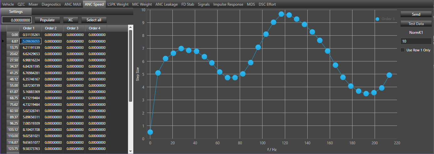
24.ANC Speed
This tab is used for setting a single value of speed across the entire frequency per Engine Order. Minimum value is 0.0. Maximum value is 2.0.
NormK1 – is used to weight the error signals to obtain an error normalized step size. 0 will imply step size is static. NormK1 is used to adjust the sensitivity of the ANC output towards short impulse like disturbances/abrupt peaks in the baseline noise in the vehicle, for example when the vehicle hits a speed bump etcetera. This is to stop the algorithm from reacting to transient changes in the vehicle driving condition. NormK1 is at 0 by default.
Depending on the device, it can be one or separate values independently of Engine Order. For each Order you can set the NormK1 depending on effort value in range: 0-33%, 34-66% and 67-100%. In this case, NormK1 is expressed in dB and after changing the values, press the Send button to send the data to DSP.

Test Data
- Send – send data to DSP
How to use grid and graph was described in 5.10.21.1
25.LSPK Weight
This tab is used for limit the contribution of some loudspeakers to noise reduction of the global sound field and vice versa. This is mainly the case in situations where acoustical problems arise in a low channel EOC system used to cancel a complex and spatially extended sound fields.
- Minimum value is -120.0
- Maximum value is 6.0
- Send – send data to DSP
How to use grid and graph was described in 5.10.21.1

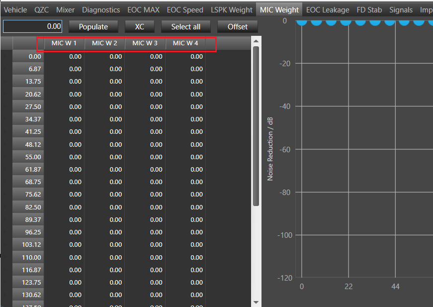
26.MIC Weight
Typically all microphones are equally weighted and the system attempts to reduce the noise field and inputs of the microphones in an average process.
Sometimes it is desirable to limit the contribution of some microphones to noise reduction of the global sound field and vice versa. This is mainly the case in situations where acoustical problems arise in a low channel EOC system used to cancel a complex and spatially extended sound fields or if the target is to only focus on the driver seat etc.
Using the “MIC WEIGHTS” tab the user can enter a specific value per microphone, per engine order and over the chosen processing frequency to control EOC feedback from mics.
The data is organized in 32 freq bins with an applied linear interpolation to increase the resolution between mic weight values in adjacent freq bins.
-120dB < Mic_wts < 0dB.
- Setting the gain to “0dB” completely disables the corresponding microphone. It has no contribution to the overall noise field reduction.
- Setting the gain to “-120 dB” enables full contribution of the feedback noise from that microphone.
Send : send data to DSP.
How to use grid and graph was described in 5.10.21.1

Make sure the number of microphones in MIC Weight is equal to m_TuneMicNum. If Vm Config is disable then m_TuneMicNum is equal to m_NumElement(# of Mic:) and if Vm Config is enable then m_TuneMicNum is equal to Num of Virtual Mics(from Additional Parameter section).
27.ANC Leakage
This tab is used for set static leakage values per EOC speaker, per EOC order and per frequency.
- Control ON/OFF – Will globally set leakage to 0.0.
- Minimum value is 0.0, Maximum value is 1000.0.
- Send button – is sending parameters to the DSP depend on the context, Settings or Dynamic Leakage Threshold.
How to use grid and graph was described in 5.10.21.1
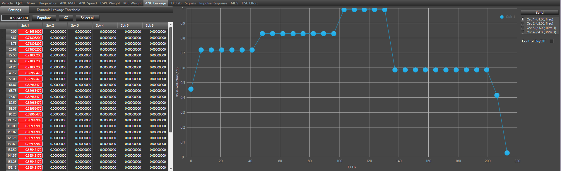
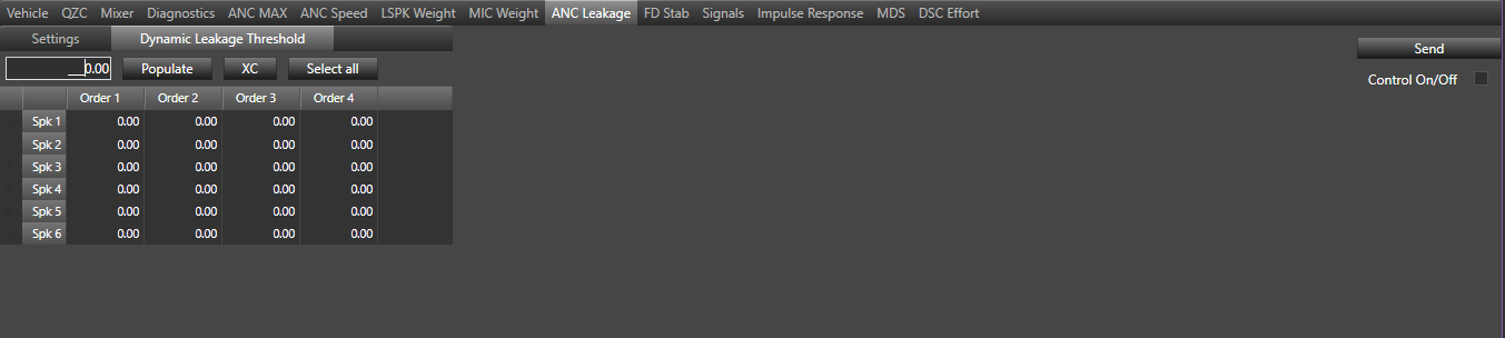
Dynamic Leakage Threshold – optional. The user can set ratio value using the Dynamic Leakage Threshold tab. Defines lower threshold limit for activating dynamic leakage. The tunable parameter for dynamic leakage is ratio value in dB. After changing the values, press the Send button to send the data to DSP.
28.FD Stab – Frequency Domain Stability
FD Stab ( Frequency Domain Stability ) contains two tabs.
- Setting tab
- Input tab
Setting Tab
The algorithm is able to register that the noise levels at the microphones are above the normal thresholds, which then interprets the noise source to be outside of the vehicle.
FD Stab page can be used for settings and inputs. Settings tab enables to set:
- Mute hold (time in seconds)
- Unmute hold (time in seconds)
- Unmute threshold (number of retries)
- Stab violation threshold
- Speaker Stab Violation Thresh (number of asymmetrical counters)
- Initial wait for exponential backoff attempts (time in seconds)
- Number of exponential backoff attempts
- Maximum wait time for exp backoff (time in seconds)
- Speaker output suppression (0-1)
- Microphone threshold factor (0-1)
- Reduction factor for retries (max value 0.001)

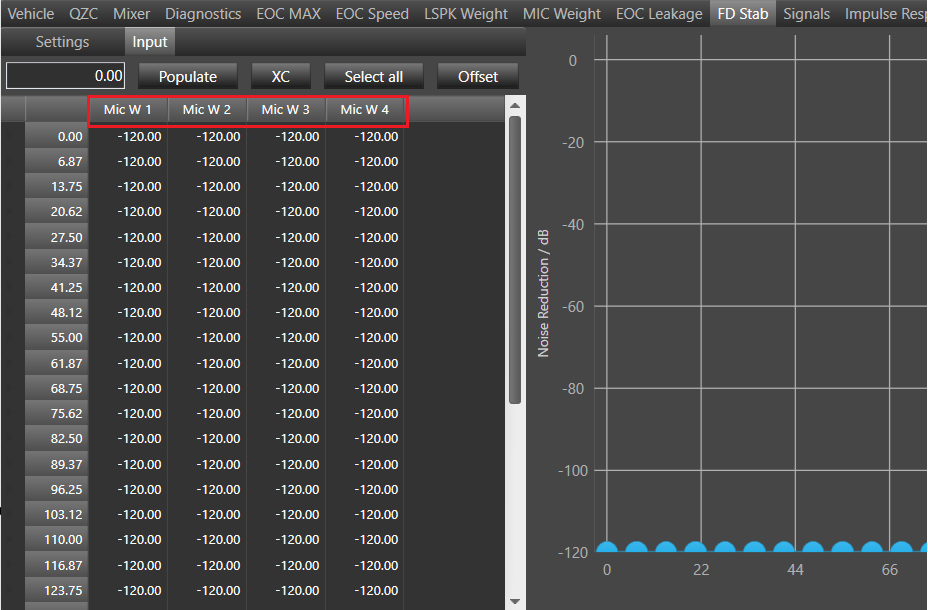
Input Tab
The EOC FD Stab should work with 1 to 8 orders. Elements depended from orders should be created dynamically based on numbers of order. Input table contains data with values from -120 to 6 dB (Noise Reduction). The chart presents dependence of Noise Reduction to frequency (f/Hz). The number of input table columns depends on number of microphones. Setting the number of orders and microphones is possible from EOC properties tab in SFD.
- Load: Load data from DSP
- Send: Send data to DSP
- Radio button list with oscillators gives a possibility to switch between data series which matches with each oscillator.
- Import from Signals – Current order only is responsible for importing MicABS data for one oscillator only (visible only if peak extension is available).
- Import from Signals – All orders is responsible for importing MicABS data for each oscillator (visible only if peak extension is available).
How to use grid and graph was described in 5.10.21.1
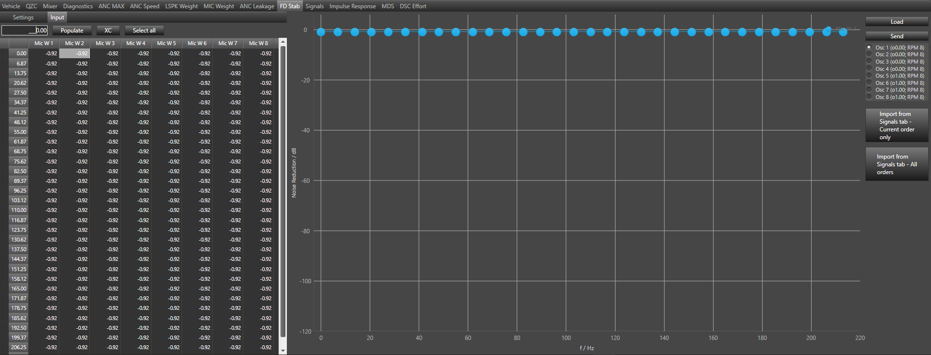
Make sure the number of microphones in FD Stab is equal to m_TuneMicNum. If Vm Config is disable then m_TuneMicNum is equal to m_NumElement(# of Mic:) and if Vm Config is enable then m_TuneMicNum is equal to Num of Virtual Mics(from Additional Parameter section).
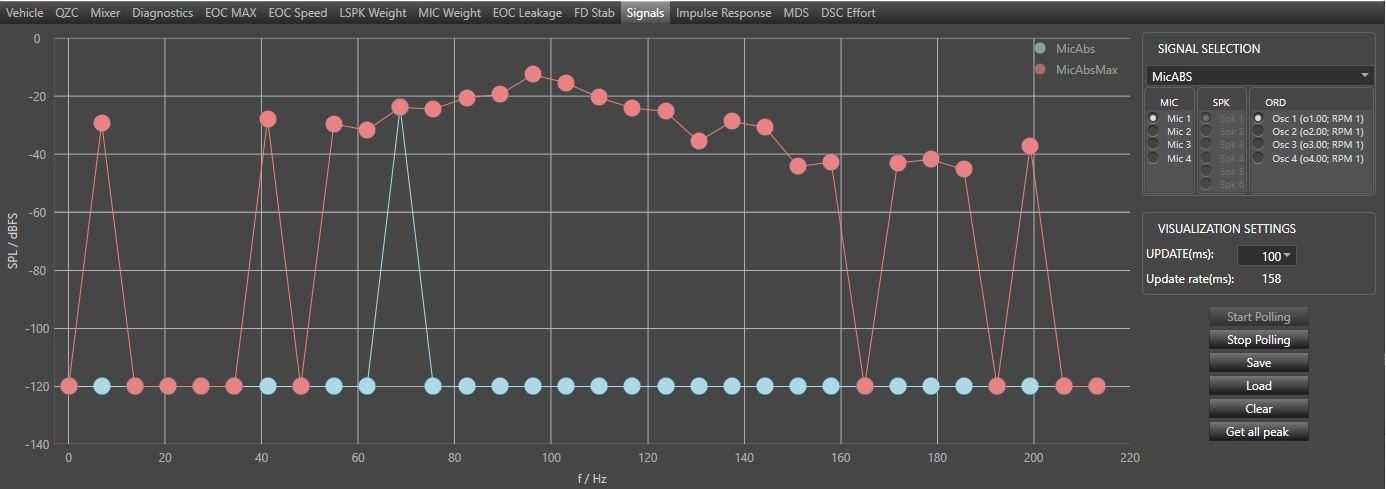
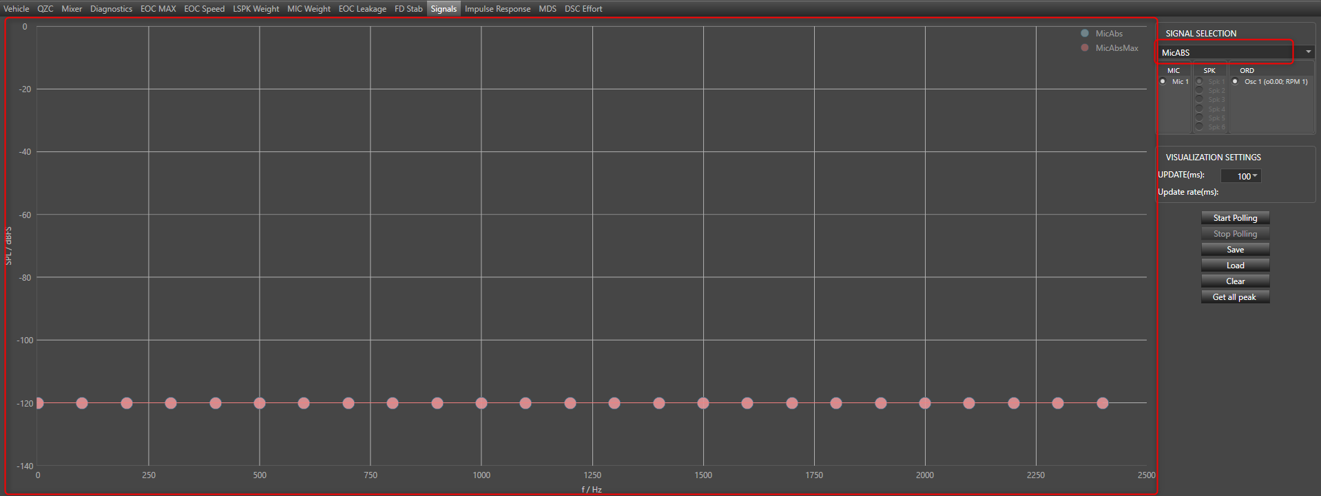
29.Signals
This tab is used for measuring selected type of signal
- Blue plot – actual values
- Red plot – peak hold values (based on the actual values received by GTT)
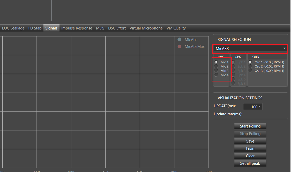
Signal Selection
- Drop down – changing selected type of signal
- Combo boxes Mic, SPK, ORD – to select proper mic, spk or order. Available in selected type of signals
Visualization Settings
- Update (ms) – intervals of chart updating
- Update rate (ms) – time between reads
- Start Polling / Stop Polling – start/stop updating chart
- Load – load data from file to selected signal
- Save – save data (for all mics/spk/ord) for selected signal
- Clear – clear data
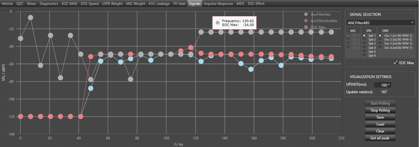
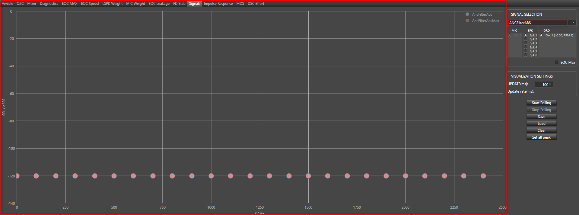
EOC Max data
Displaying EOC Max data directly on the signals graph is possible by selecting EOC Max check box when ANCFilterABS signal is selected.
The EOC Max data are retrieved from EOC Max panel and overlay on the chart as an additional grey series.
Make sure the number of microphones in Signals – MicABS is equal to m_TuneMicNum. If Vm Config is disable then m_TuneMicNum is equal to m_NumElement(# of Mic:) and if Vm Config is enable then m_TuneMicNum is equal to Num of Virtual Mics(from Additional Parameter section).
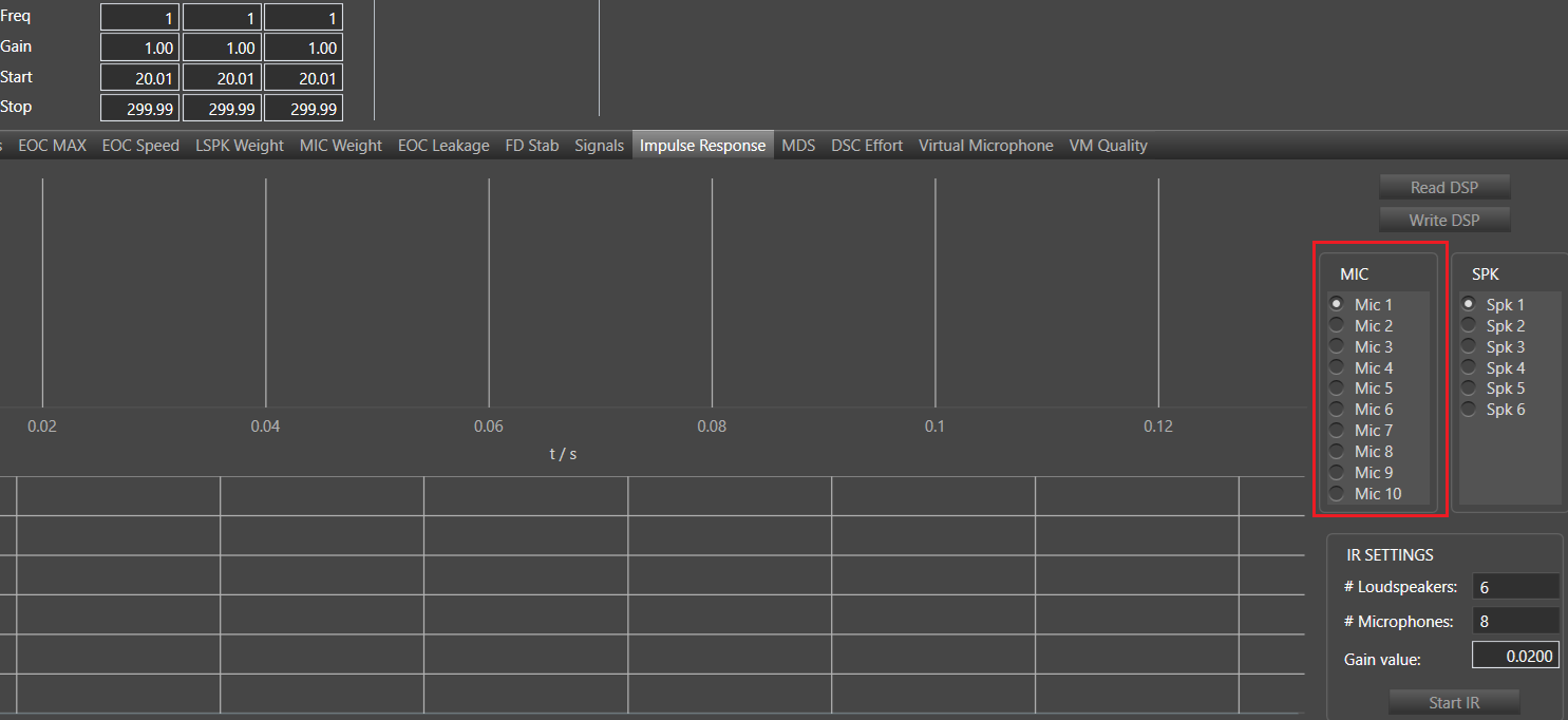
30.Impulse Response
The acoustic transmission path from the loudspeaker to the microphone is usually referred to as a “secondary path” of the ANC system, whereas the acoustic transmission path from the noise source to the microphone is usually referred to as a “primary path” of the ANC system. The corresponding process for identifying the transfer function of the secondary path is referred to as “secondary path system identification”. In this context, this is the transfer of sound from the algorithm output (via speakers) to the algorithm input (via error microphone). This measurement represents the acoustic transmission path from the acoustic loudspeaker to the error microphone is applied to the FXLMS algorithm. The frequency response (i.e., magnitude response and phase response) of the secondary path system of the ANC system may have a considerable impact on the convergence behavior of the algorithm’s adaptive filter, and thus on the stability and the speed of the adaptation.
- Read DSP – read impulse response data from DSP
- Write DSP – write impulse response to DSP
- Mic and Spic radio buttons – is used for switching between microphones and speakers to see visualization of data for selected mic and spic
IR Settings
- Loudspeaker – loudspeaker from which will be send signal
- Microphone – microphone to which will be send the signal
- Gain – value of gain
- Save to flash – if the data should be saved in the device flash
- Start IR – start generating impulse response according to the settings above
From main menu user can export and import time domain and frequency domain data to the file.

The graphs in the impulse response tab are plotted based on the values from the following state variables
Make sure the number of microphones in the mixer settings is equal to m_NumElements(‘# of Mics:’ fromAudio Object property section).
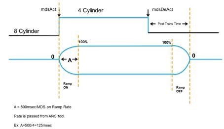
31.MDS
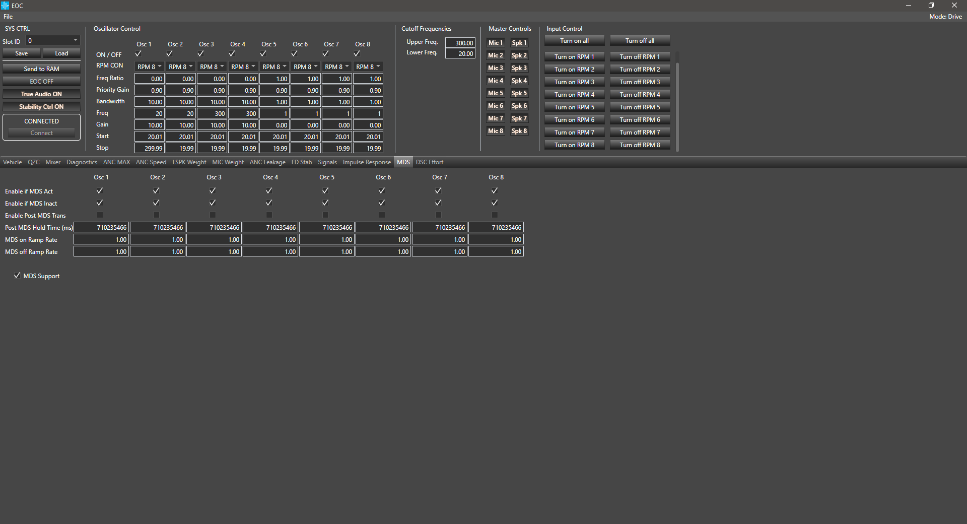
The following diagram depicts the interpretation of each parameter in the above table. The line is the state of the engine, the bottom line shows the ANC output for a particular engine order assuming it is enabled when MDS is Active and after the MDS transition.
- MDS is supporting from 1 to 8 orders. Above screen is presenting configuration for 8 orders.
- MDS Support – Enable the Algorithm to handle MDS transitions.
31.1.DDF MDS EnumSV Template
Important change in this template have been introduce in August_wave release. Template have been change to provide correct bit mask setting.
Important! Together with this change backward compatibility have been broken because of changes in DDF MDS EnumSV bit mask.
Bit mask settings in EnumSV of m_tMDSOrderFlags state variable are following:
| Oscillator Index |
m_nActiveMDSTransOrd <Mask> |
m_nActiveNotMDSOrd <Mask> |
m_tMDSOrderFlags <Mask> |
| 0 | 256 | 65536 | 16777216 |
| 1 | 512 | 131072 | 33554432 |
| 2 | 1024 | 262144 | 67108864 |
| 3 | 2048 | 524288 | 134217728 |
| 4 | 4096 | 1048576 | 268435456 |
| 5 | 8192 | 2097152 | 536870912 |
| 6 | 16384 | 4194304 | 1073741824 |
| 7 | 32768 | 8388608 | 2147483648 |
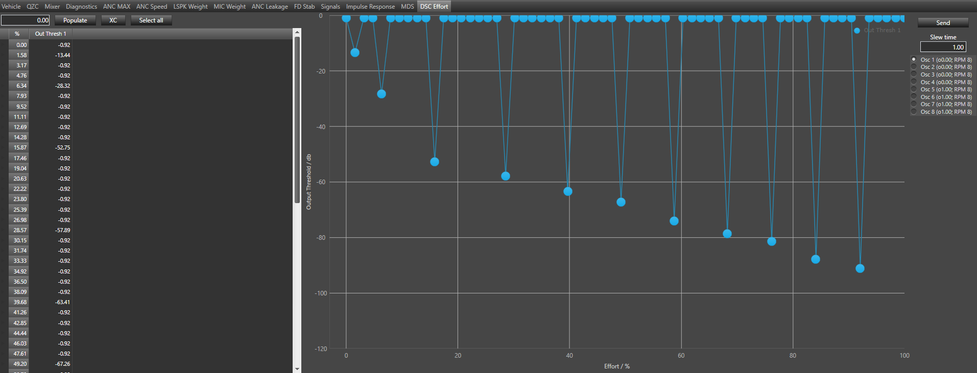
32.DSC Effort
The DSC Effort (Dynamic Stability Control Effort) provides the capability to change how quickly the EOC algorithm reacts based on effort, tunable from 1 msec to 1000 msec in steps of 1 msec via GTT. It supports tuning the Output Threshold vs. Effort in a “DSC Effort” tab (Effort is used for calculate Output Thresholds). The algorithm uses both microphone and output thresholds to counter near maximum or maximum thresholds. DSC Effort tab contains table with „Out Thresh“ column where values can be set from -120 to 0 dB for each of 64 percentage effort ranges. It means that all 64 table rows indicate effort values from 0% to 100%.
How to use grid and graph was described in 5.10.21.1
- Slew Time field can be set from 1 to 1000 ms and is related to exceeding the output threshold.
- Send button is responsible for sending data to DSP, for all the Effort Table values.
33.Flexible Block Length
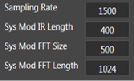
EOC audio object supports flexible block length from audio object version 19.02.00. Supported block length values are 8, 12, 16, 24 and 32. The block length can be configured in device view.
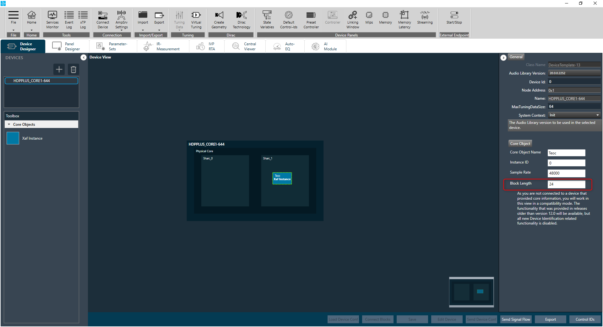
EOC panel supports this feature. In order to support flexible block length feature, value of state variable “SamplingRate” is used for calculations in EOC panel.
Based on the block length used, sampling rate can be adjusted and that will reflect in all calculations where sampling rate is used in EOC panel.

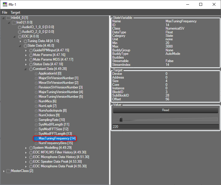
34.Flexible Frequency Bins
The EOC audio object supports flexible frequency bins feature. This feature allows you to configure maximum tuning frequency and number of tuning frequency dynamically in the EOC audio object. In earlier versions of EOC audio object, the “MaxTuningFrequency” value was fixed to 220 and the “Number of tuning frequency bins” values was fixed to 32.
If the state variable “MaxTuningFrequency” and additional parameter “Number of tuning frequency bins” are not present in the EOC Audio object, then the default values of the “MaxTuningFrequency” value will be 220 and the “Number of tuning frequency bins” value will be 32.
The flexible frequency bins feature is available from 19.02.01 EOC audio object version.
MaxTuningFrequency: The max tuning frequency can be configured using state variable “MaxTuningFrequency”.
- Range: 20 to 3000
- Default Value: 220
- Location: State Data > Constant Data > MaxTuningFrequency
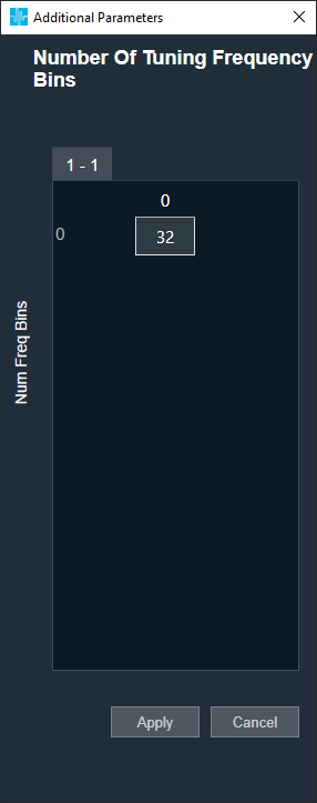
Number of tuning frequency bins: In additional parameter of EOC audio object, you can configure number of tuning frequency bins.
- Range: 16 to 512
- Default Value: 32
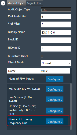
Based on the configured “MaxTuningFrequency” and “Number of Tuning Frequency Bins”, the frequency bins are calculated.
Frequency bins = MaxTuningFrequency/ Number of Tuning Frequency Bins
The flexible frequency bins support all features in following tabs, including Save and Load tuning data in EOC panel.
- EOC MAX
- EOC Speed
- LSPK Weight
- MIC Weight
- EOC Leakage
- FD Stab
- Signals

The above image shows the graph and table for the EOC MAX tab; the value will update based on the “MaxTuningFrequency” and calculated “Frequency bins”.
Here the table and graph of EOC Max tab is updated with MaxTuningFrequency 2500 and Number of Tuning Frequency Bins 25. So there are 25 data points in the graph and 25 rows in the table, with a bin size of 100(2500/25). The same frequency bins are applied in the other tabs as well.
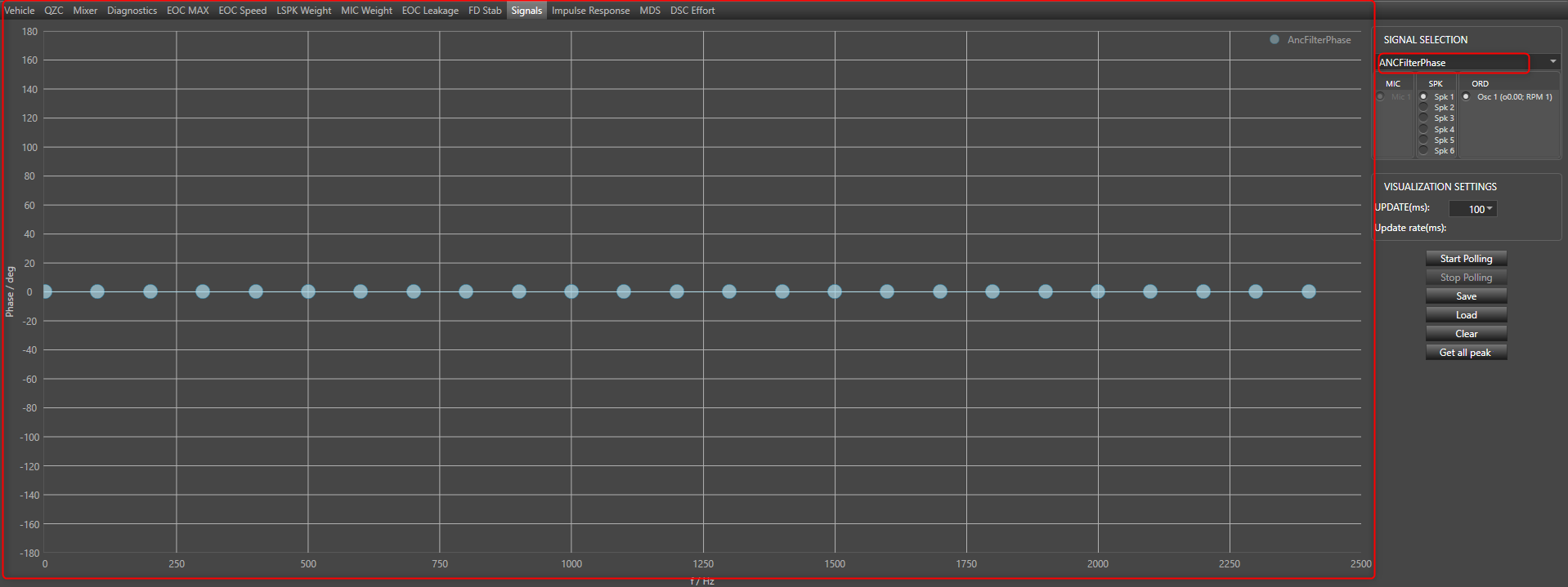
In case of “Signals” tab, all three graphs MicABS, ANCFilterABS, and ANCFilterPhase are updated with these frequency bins.
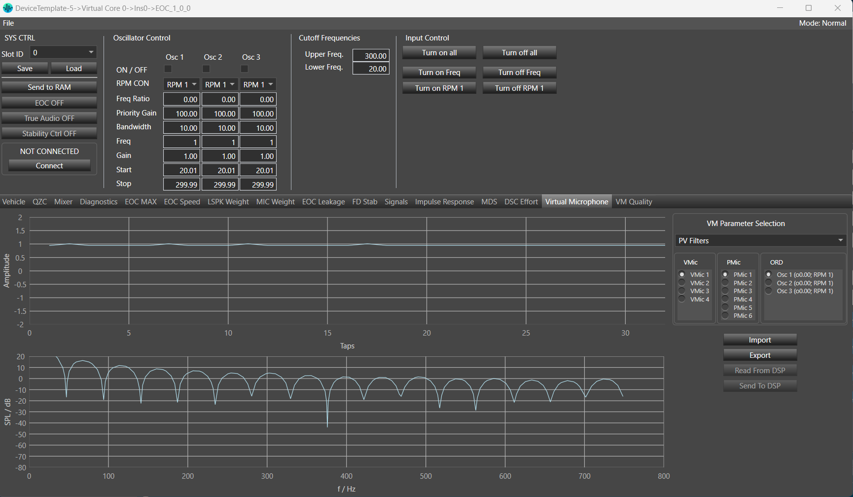
35.Virtual Microphone
You can monitor and tune the parameters of the Virtual Microphone such as PV filters, remote weights, and virtual weights. Options to send, receive, import, and export are available in this tab. You can monitor any parameters from the Virtual Microphone parameter in the graph.
This tab also includes the amplitude and frequency response graphs. You can choose any of the three options: VMic, PMic, or ORD.
This tab in EOC panel will be only visible when Virtual Mic is enabled from additional parameter section.
By default PV Filters from VM Parameter Selection , VMic 1 from VMic , PMic 1 from PMic and Osc 1 from ORD will be selected on panel launched.
VM Parameter Selection: You can select any option out of PV filters, Remote Weights and Virtual Weights.
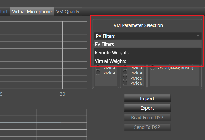
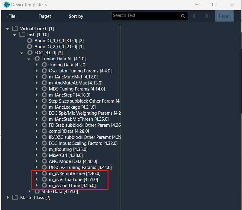
These three parameters are mapped with state variables given in state variable tree.
- PV filters mapped with “m_pvCoeffTune”.
- Remote Weights mapped with “m_pvRemoteTune”.
- Virtual Weights mapped with “m_pvVirtualTune”.
- Changing any value in “m_pvCoeffTune”, will reflect in graph on the selection of PV Filters.
- Changing any value in “m_pvRemoteTune”, will reflect in graph on the selection of Remote Weights.
- Changing any value in “m_pvVirtualTune” , will reflect in graph on the selection of Virtual Weights.
VMic: This is virtual mics. You can select any option from given virtual mics. The number of VMic depend upon ‘Number Of Virtual Mics’ parameter from additional parameter section. Minimum number of VMic is 1 and maximum number of VMic is 8.
Number of VMic = ‘Number Of Virtual Mics’ = 4 (example)

PMic: This is physical mics. You can select any option from given physical mics. The number of PMic depend upon ‘Virtual Mic Enable’ , ‘Number Of Virtual Mics’ parameter from additional parameter section and ‘# of Mics’ (m_NumElements) from audio object property section.
Virtual Mic Enable: Min =0(disable), Max =1(enable)
Number Of Virtual Mics: Min =1, Max =8
Set value of ‘Virtual Mic Enable’ to 1 and ‘Number Of Virtual Mics’ =4 and ‘# of Mics’ (m_NumElements) = 10
The number of physical mics PMic = 10 – 4

ORD: This is order and depends upon ‘Num Order’ from EOC additional parameter section. Minimum number of order is 1 and maximum is 8.
Number of order = ‘Num Order’ = 3(example)

Time Domain Graph: This graph will display the actual value of the state variables as per selected VMIc, PMIC, and ORD.
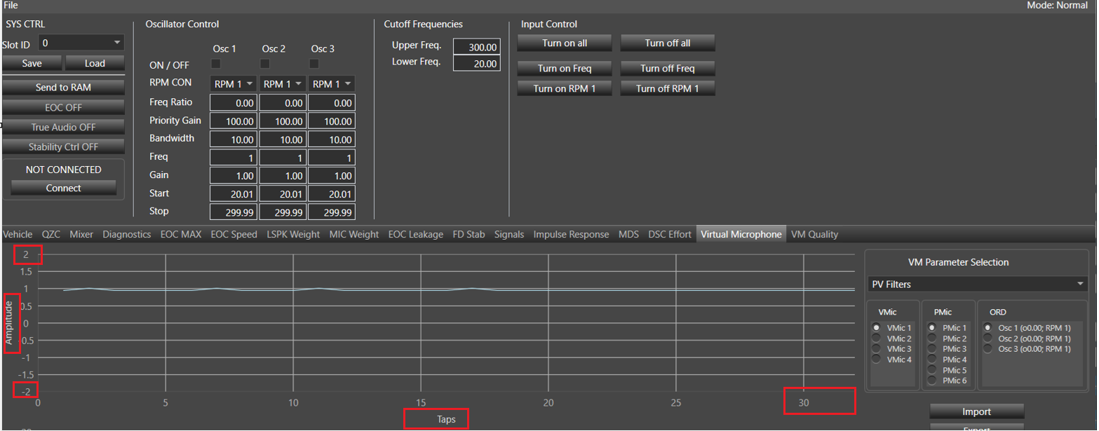
PV filters is selected-
- Y axis title is Amplitude.
- Y axis min and max range will be as per value given in state variable min and max (example if maximum value for any given state variable Order 1. Coefficient 0 [0] is 50 and minimum value for any given state variable Order 2. Coefficient 3 [3] is -50 then Y axis min range will -50 and max range will be 50) . If the given state variable value is less than 10 then max range will be equals to the given sv value +1 and min range will be – (sv value +1). If the given state variable value is greater than 10 then max range will be equals to the given (sv value %10 +1)*10 and min range will be – (max range).
- X axis title will be Taps and range will be from 1 to VM- length of PV Filters(example 32).
VM- length of PV Filters: Min =32, Max =128
In below screen shot maximum sv value is given 0.878243 so max range = 1(ceiling value) +1 = 2 and min range will be -2.
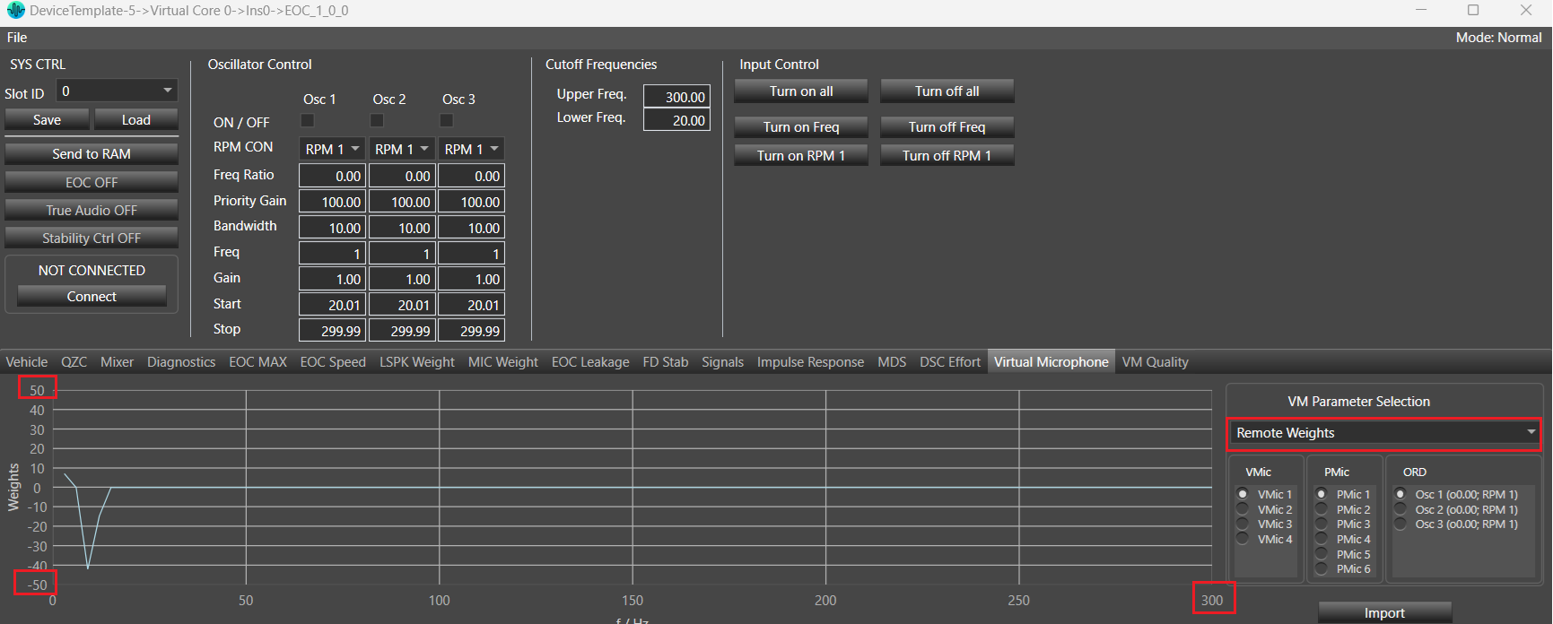
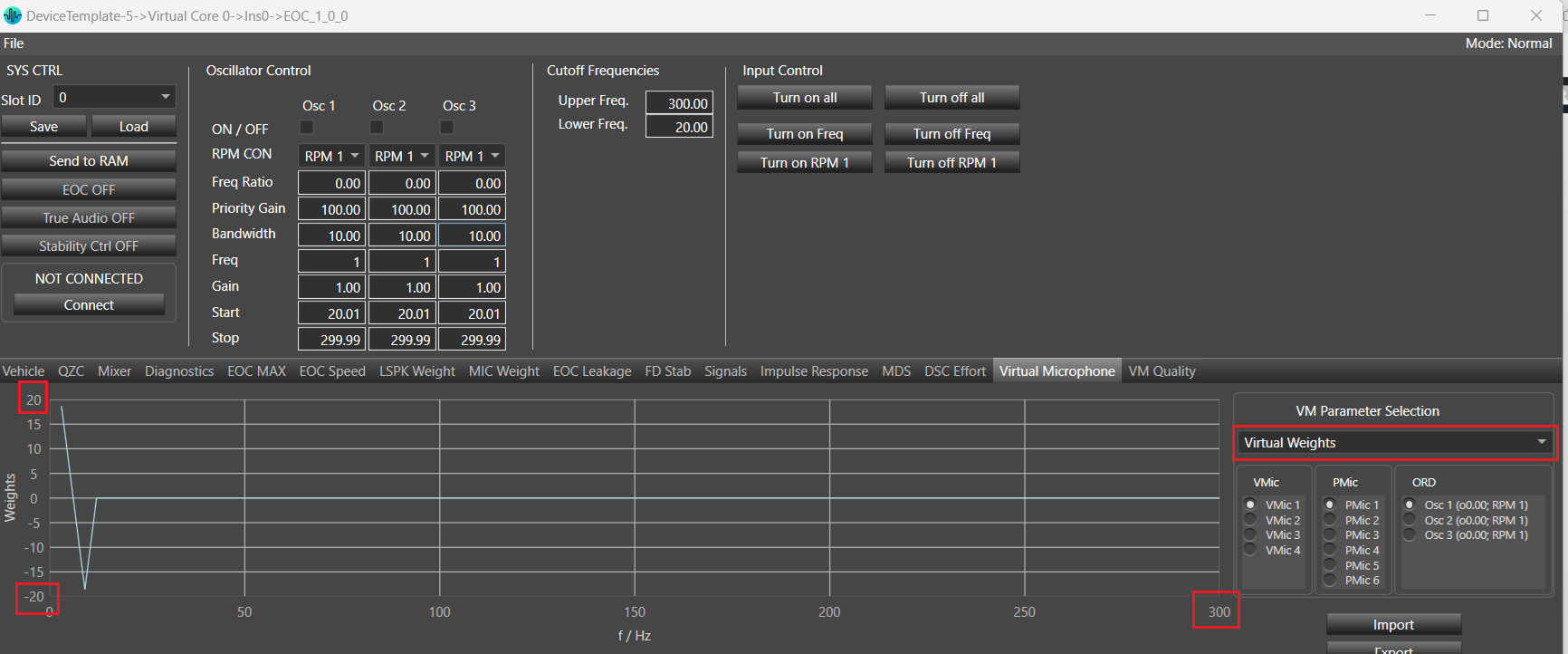
Remote Weights/ Virtual Weights selected.
- Y axis title will be Weights.
- Y axis min and max range will be as per value given in state variable min and max (example if maximum value for any given state variable Order 1. Coefficient 0 [0] is 50 and minimum value for any given state variable Order 2. Coefficient 3 [3] is -50 then Y axis min range will -50 and max range will be 50).
- X axis title will be f/Hz and min range will be 3 and max range will be equal to the value of VM-length of Remote and Virtual Weights =100 example)*3.
VM-length of Remote and Virtual Weights: Min =100, Max =400
Frequency Response Graph: Frequency response gets calculated with given amplitude values.

Frequency Response Graph is available only for PV Filters.
Export: This is used to export all the state variable’s (m_pvRemoteTune, m_pvVirtualTune and m_pvCoeffTune irrespective of selected VM parameter) value to the excel sheet in specific format.
Steps to Export:
- Click on Export button.
- Browse folder window will be displayed.
- Provide filename and click on Save.
By default file name will be “VmExport”.

Below is exported file format:
- 3 Valid Sheets
- pvFilterCoeffRead corresponds to State variable m_pvCoeffTune.
- pvRemoteWeightRead corresponds to State variable m_pvRemoteTune.
- pvVirtualWeightRead corresponds to State variable m_pvVirtualTune.
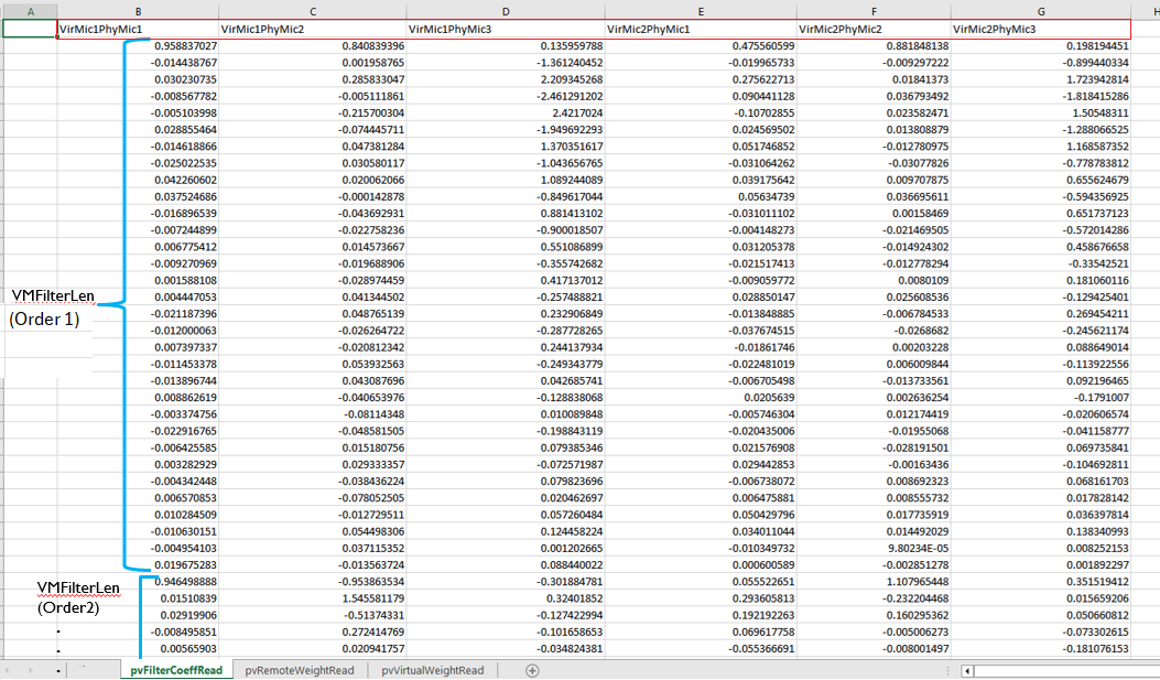
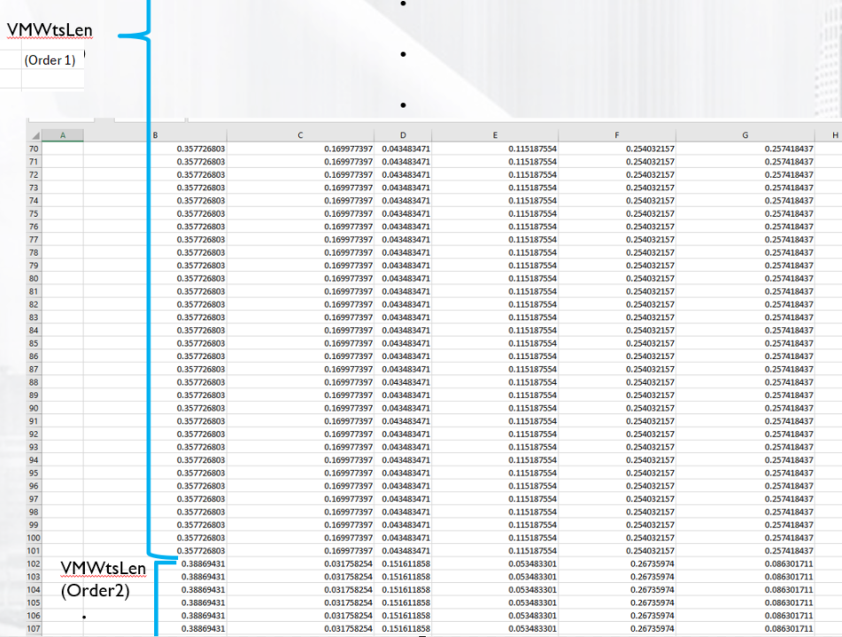
2. Data Layout
- Column A in each of the 3 sheet is empty.
- Data starts in column B.
- Column ordering is VirMic1PhyMic1, VirMic1PhyMic2, VirMic1PhyMic3.
VirMic2PhyMic1, VirMic2PhyMic2, VirMic2PhyMic3
(assume m_PhyMicNum=3 , m_VirMicNum = 2, VM- length of PV Filters =32, Num.Order=4 and VM-length of Remote and Virtual Weights =100 )
- pvFiltersCoeffRead sheet
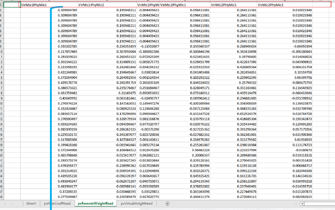
- pvRemoteWeightRead and pvVirtualWeightRead sheets will look like as per below screen shot.
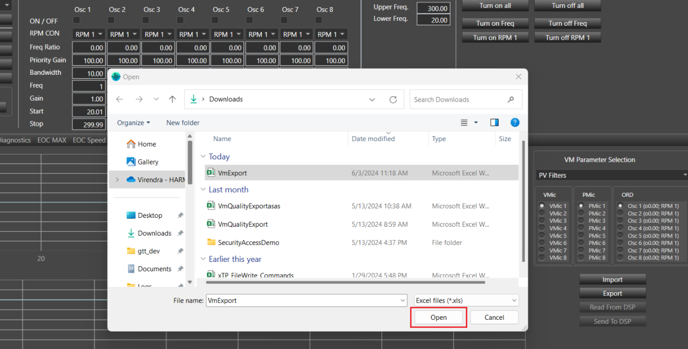
Import: This is used to import all values from excel sheets (pvFiltersCoeffRead, pvRemoteWeightRead and pvVirtualWeightRead) and update the graph and respective state variable’s (m_pvRemoteTune, m_pvVirtualTune and m_pvCoeffTune ) value .
Step to Import:
- Click on Import
- Browse the file location path
- Click on Open
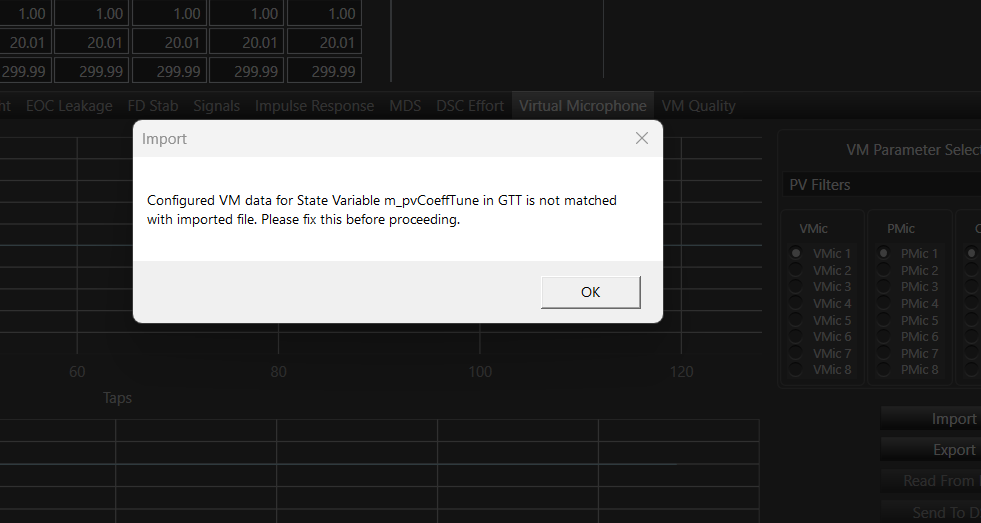
Warning message will be displayed if importing file is not matching with configured parameters (Num.Orders, Num. of Virtual Mics, Number of Physical mics…)
Read From DSP: This is used to read the latest state variable’s value from the device. Once user click on ‘Read From DSP’, It will fetch the latest value and update the state variable (m_pvCoeffTune, m_pvRemoteTune and m_pvVirtualTune) and graph in Panel.
Send To DSP: This is used to send the latest state variable’s (m_pvCoeffTune, m_pvRemoteTune and m_pvVirtualTune) value to the Device.
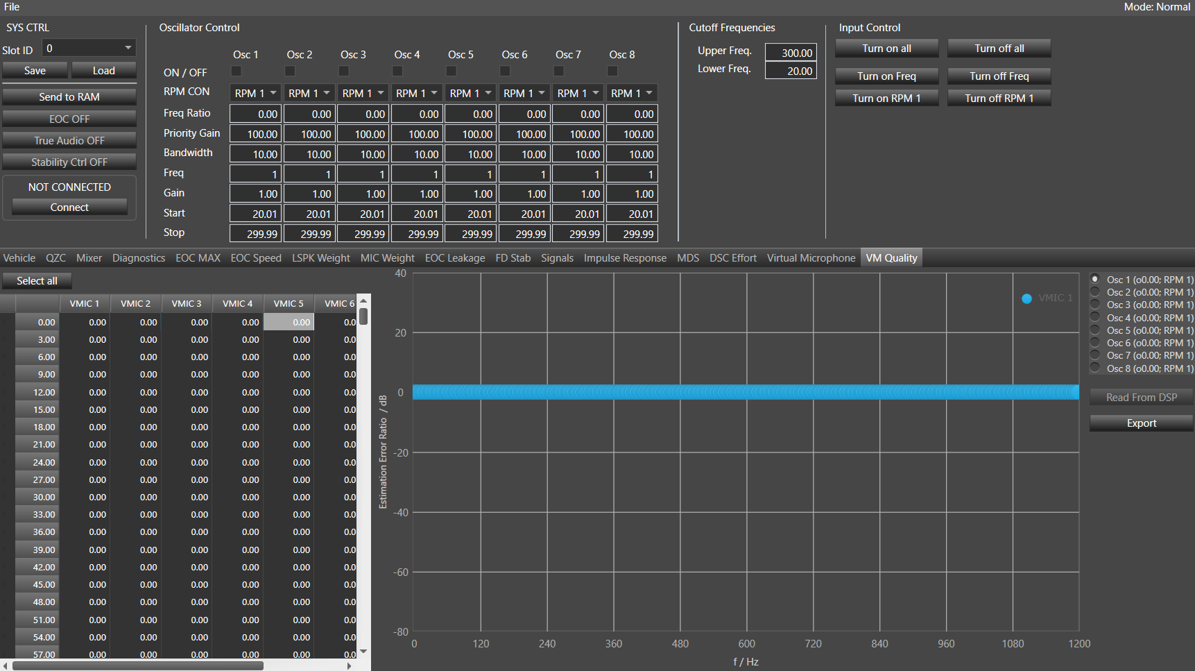
36.VM Quality
The VM Quality tab displays the value of the SV Virtual Microphone estimation error (VM Estimation Error), which is state data and not tuning data. These results will be presented in a table and a graph.
You can select any option from numOrders. Legends for m_VirMicNum will be displayed in the graph. The read option will be provided to read the Virtual Microphone estimation error from the device, and state variables will be updated after clicking on ‘Read From DSP’. After clicking the Export option, the Virtual Microphone estimation error will be exported to an Excel file. The error in virtual microphone estimation will be displayed as linear in a table and as dB in a graph.
VM Quality tab in EOC panel will be visible if Virtual Mic is enabled from additional parameter section.
Following is the state variable tree structure of VM Estimation error State variable with given Num. of Virtual Mics =4, Num.Order =3 and VM-length of Remote and Virtual Weights=100.
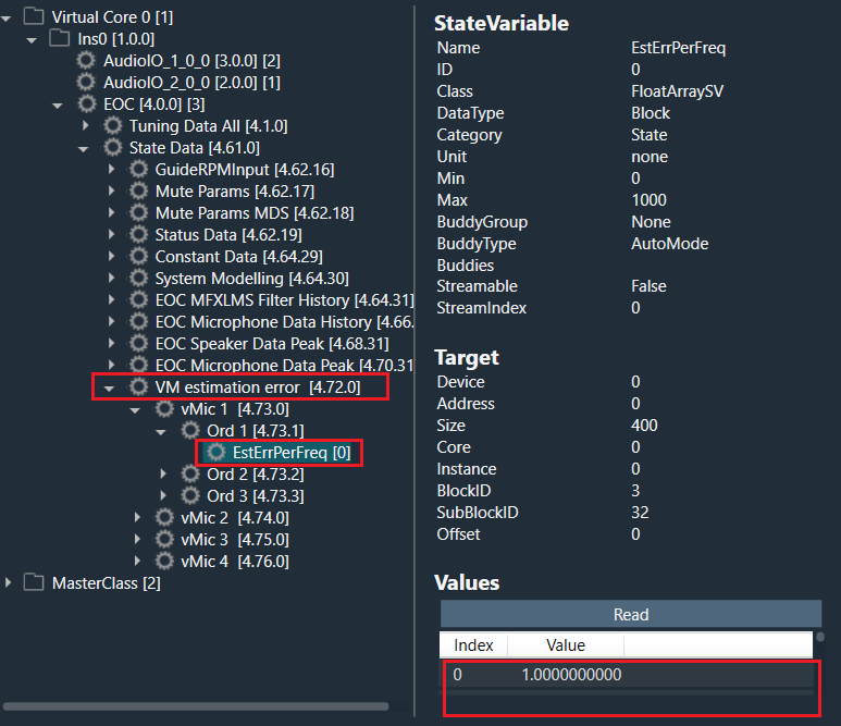
ORD: You can select any option from num order and as per selection value in in table as well as in dB graph will be updated. Minimum Order count is 1 and maximum order count is 8.
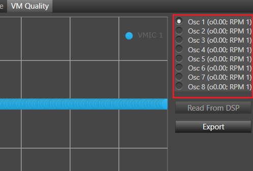
Table Representation of VM Estimation error: Each ‘EstErrPerFreq’ state variable will have the number of value equals to the number of ‘VM-length of Remote and Virtual Weights’. Each value will be displayed as linear in table. Number of virtual mics(VMIC 1, VMIC2…) will be equals to the number of ‘Num of Virtual Mic’. Table value will range from 0 to (“VM-length of Remote and Virtual Weights”*3 )-3 for each virtual mic.
Assume Num. of Virtual Mics =4, Num.Order =3 and VM-length of Remote and Virtual Weights=100 so below table will be displayed as per below screen shot.
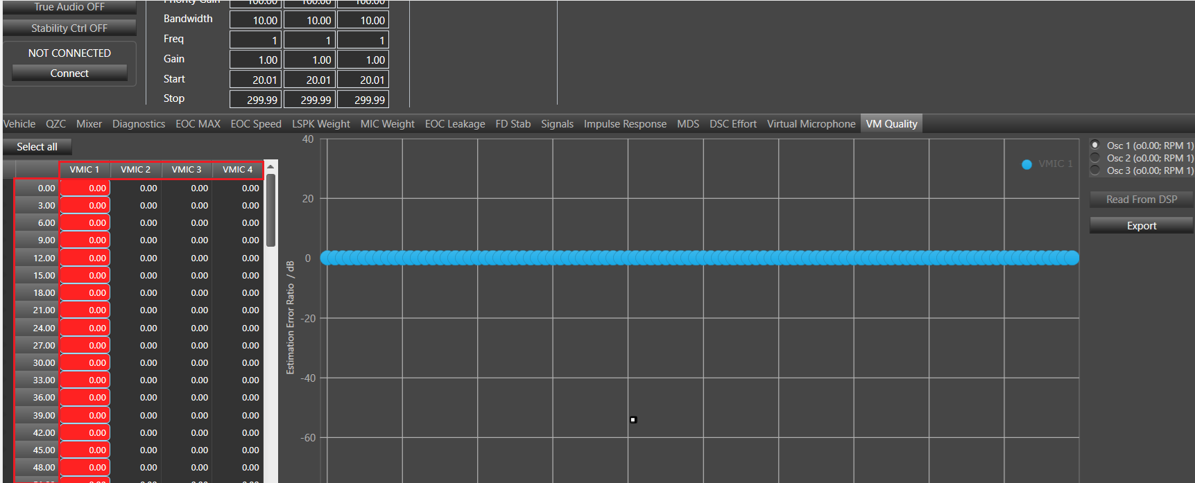
You can select individual virtual mic by clicking on the respective column or all virtual mics by clicking on ‘Select All’ and all the selected virtual mics can be seen in dB graph with all the legends.
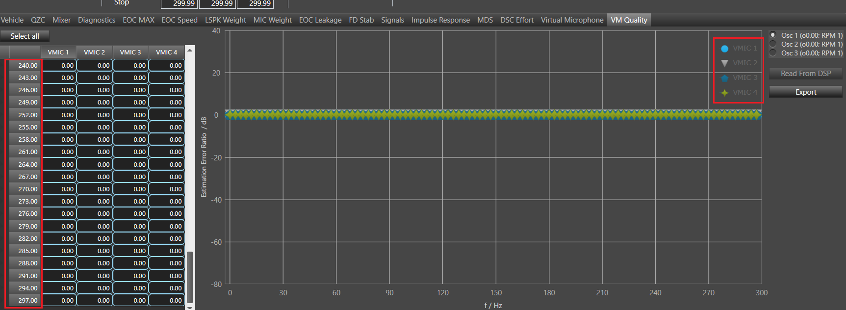
dB Representation of VM Estimation error: Each value of ‘EstErrPerFreq’ state variable will be converted in dB by formula 20 * log10(VM estimation error). Y axis Estimation error/dB max and min value will be 40 and -80 respectively. X axis f/Hz, min and max will be 0 and ‘VM-length of Remote and Virtual Weights’*3.
Read From DSP: This is used to read the Virtual Microphone estimation error from the device and state variables will be updated after clicking on ‘Read From DSP’.
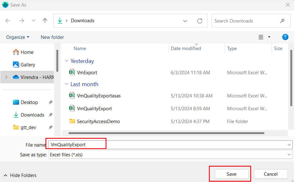
Export: Export option will be provided to export the Virtual Microphone estimation error and all errors will be exported to excel file after clicking on Export.
Steps to export:
- Click on Export.
- Browse to the destination folder and give the file name(by default file name will be “VmQualityExport”).
- Click on Save.
Assume Num. of Virtual Mics =4, Num.Order =3 and VM-length of Remote and Virtual Weights=100 so exported file column name will be- vMic 1 Ord1, vMic 1 Ord2, vMic 1 Ord3, vMic 2 Ord1, vMic 2 Ord2, vMic 2 Ord3, vMic 3 Ord1, vMic 3 Ord2, vMic 3 Ord3, vMic 4 Ord1, vMic 4 Ord2, vMic 4 Ord3
Each column will have the number of value equals to the VM-length of Remote and Virtual Weights =100(example).
Exported file will look like as per below screenshot.
