When at least one device is created, the user can start defining signal flows for the device.
Open the GTT, click on a device instance in the room and look for tab Device. Signal flow designer can also be opened by double clicking on the device instance.
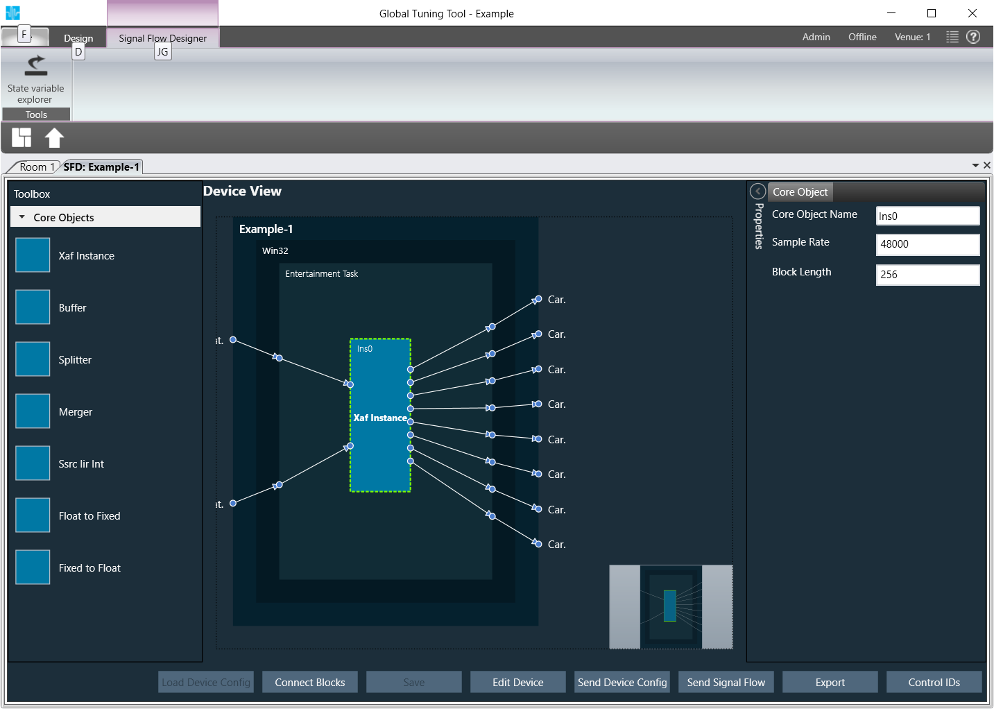
The GTT surface will be displayed.
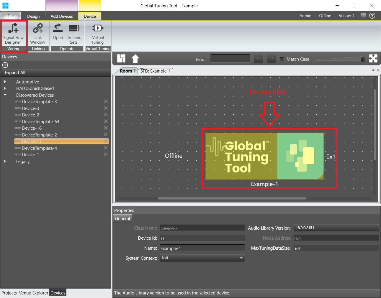
Double Click on instance to launch Signal Flow Designer.
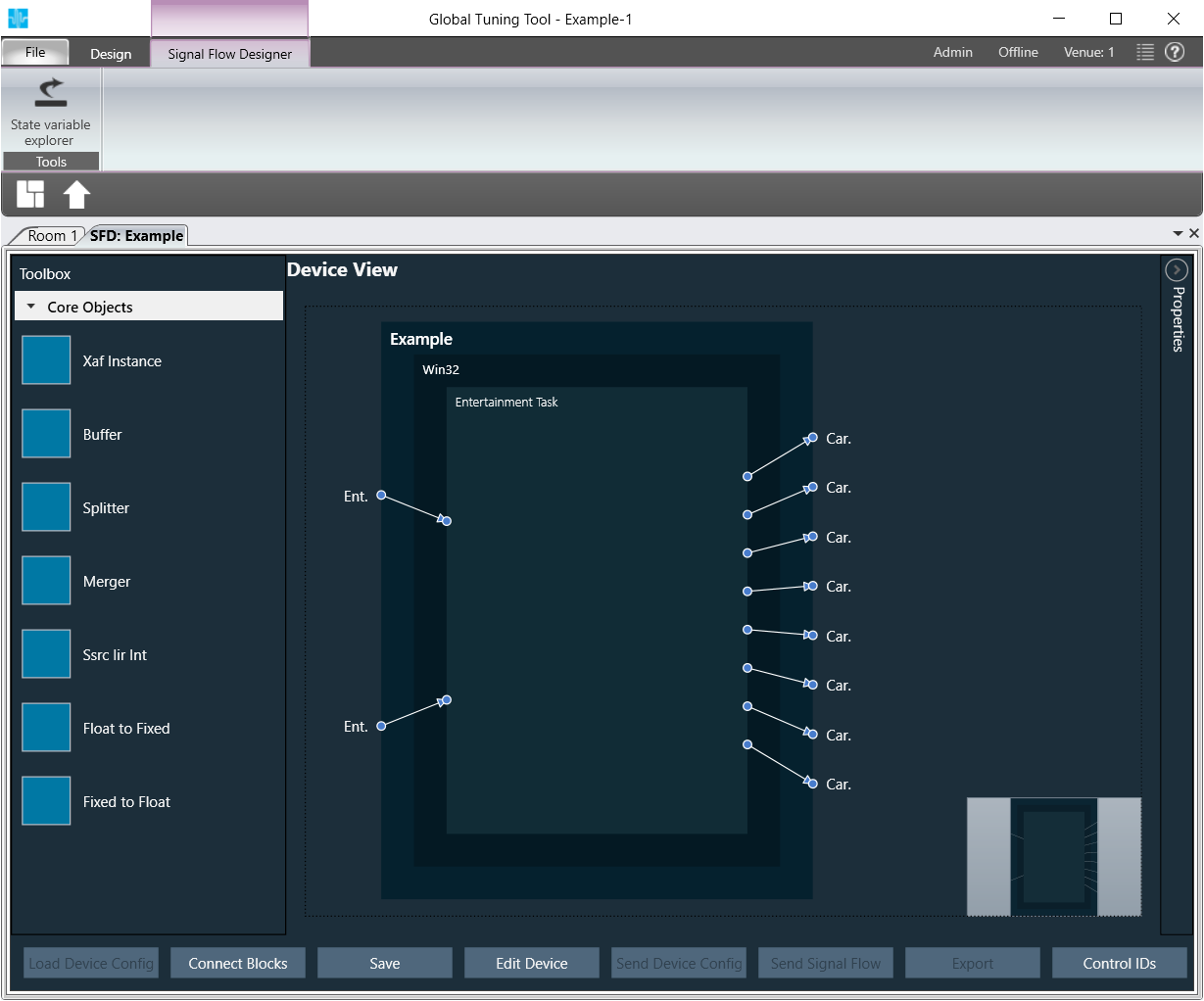
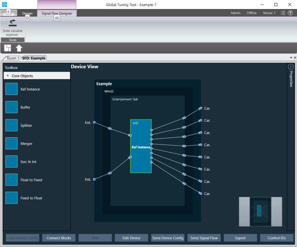
The Signal Flow Designer will be displayed.
Click on the device you previously created.
One or several boxes will be displayed on the right depending on the number of cores you have configured for your device in the setup or how many cores your real device has.
On opening Device designer view, a notification would show up to inform the user to to verify the core type selections. User has the option to hide the notification on further usage.
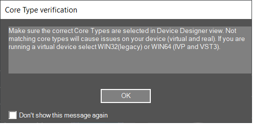
If you are running a virtual device select WIN32(legacy) or WIN64 (IVP and VST3).
Not matching core types will cause issues on your device (virtual and real).
The device view of signal flow designer has two modes:
- Static mode for manually created devices
- Wiring mode for discovered devices
Static mode
‘Load core objects’ and ‘Send Device Config’ are not available in static mode
In the toolbox there is only xAF instance, no further core objects
Add an xAF instance from the left box by dragging and dropping it in one of the virtual core(s).
A popup window will be displayed where you can configure input and output channel count of the additional xAF instance.
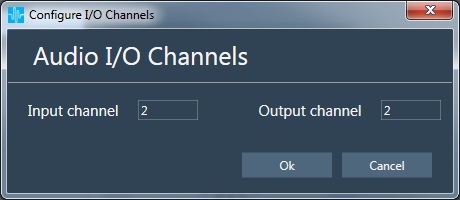
The instance will be represented by a blue box.
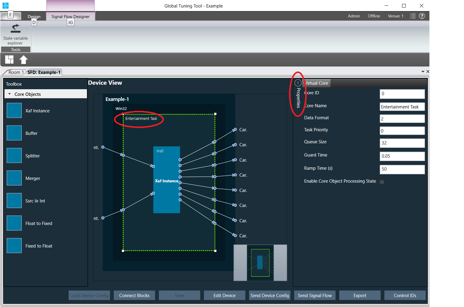
Select a virtual core and view core properties
Virtual core properties will be shown on left side.
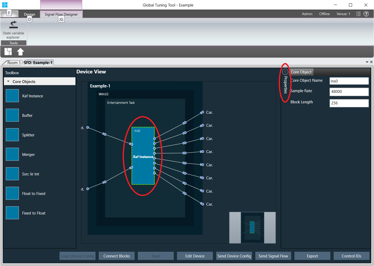
Select an xAF instance and view instance properties
Instance properties will be shown on left side.
Wiring mode
For further information on the new wiring mode, please refer to the GTT Basic guide in the section Device Identification – Load Core Objects
Functionality that is valid for both modes (legacy mode and wiring mode)
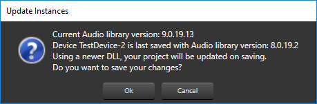
Click Save
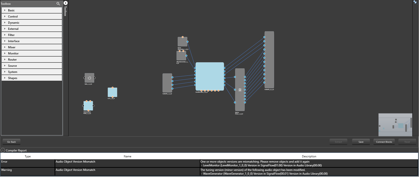
If there is a version mismatch between the current audio library version and version data present in the device, a warning message pops up
To proceed to the flow definition window double-click the added instance
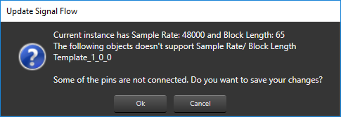
If there a mismatch between Sample Rate/ Block Length of instance signal flow and current audio object in the toolbox, then a warning message pops up and corresponding object will be disabled in the toolbox
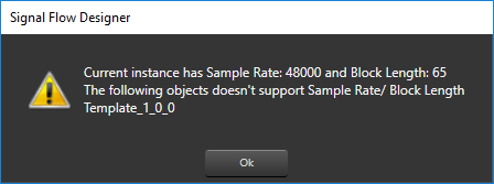
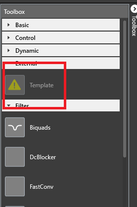
Disabled audio object
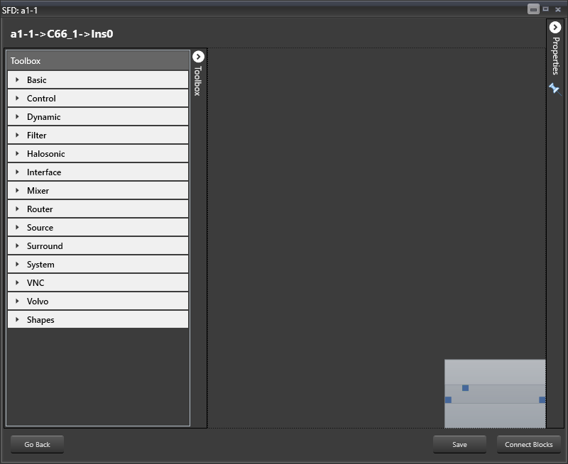
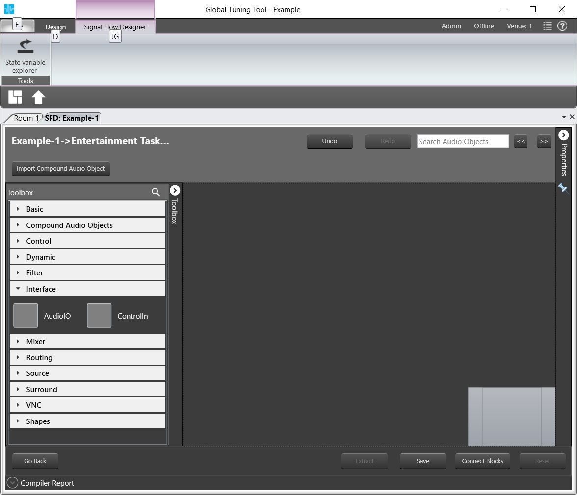
The flow definition window will be displayed, which contains 4 basic parts:
- Audio blocks toolbox (on the left)
- The designer area (center of the screen)
- Properties fly-in (on the right)
- Commands bar (at the bottom)
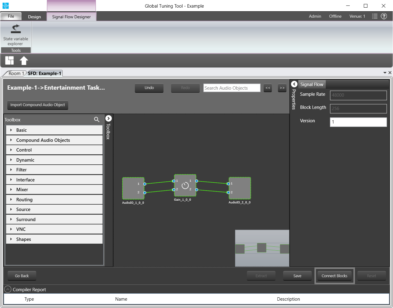
The first step in the signal flow definition process is filling in the signal flow properties:
- Sample Rate – this is the sample rate that will be applied to all the audio blocks in the signal flow
- Block Length – required internally by the xAF framework
Click on Properties.
The properties settings for the signal flow will be opened.
Now you can proceed to define the actual building blocks of the signal flow:
Open the category Interface from the Toolbox
AOs of the category Interfaces will be displayed.
AOs of Category Interfaces
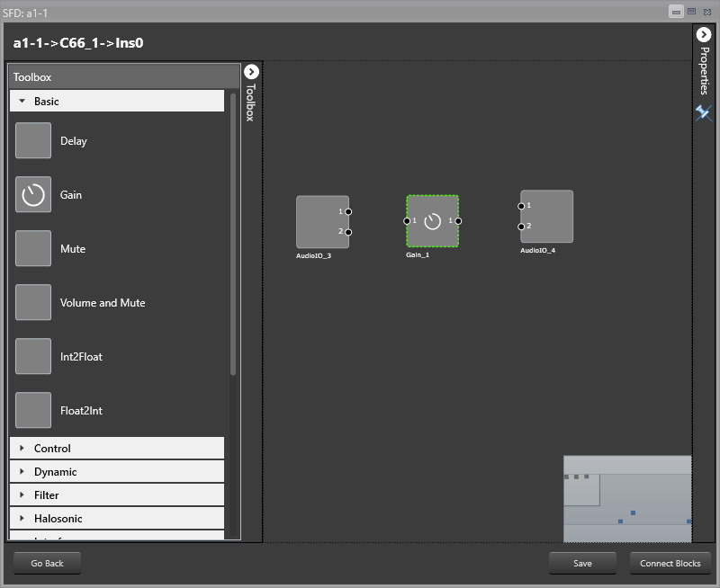
Drag and drop two AudioIO objects in the Signal Flow Designer
Drag and drop a Gain object from the Basic category in between the AudioIOs.
The AOs will be displayed SFD.
Select the Gain object and click on Properties at the top right of the window.
The properties menu for the Gain object will be opened.
Here you can modify the number of channels > Change to 2 channels for this sample.
The number of channels defines how many connectors will be assigned to the AO. You can assign as many channels as you configured for your device in chapter GTT.
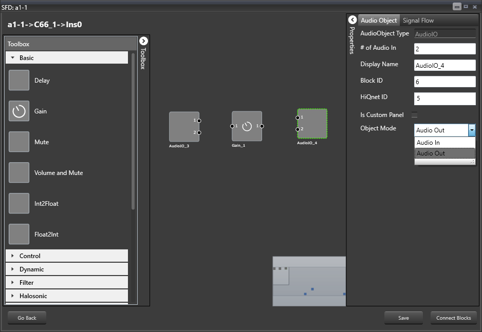
Open the Properties for one of the AudioIO objects

Select Audio Out from the Object Mode drop down menu.
Now you have an input and output object as well as an object to simulate sound volume change.
Hold Control and select all three AOs.
Click on Connect Blocks to connect the AOs.
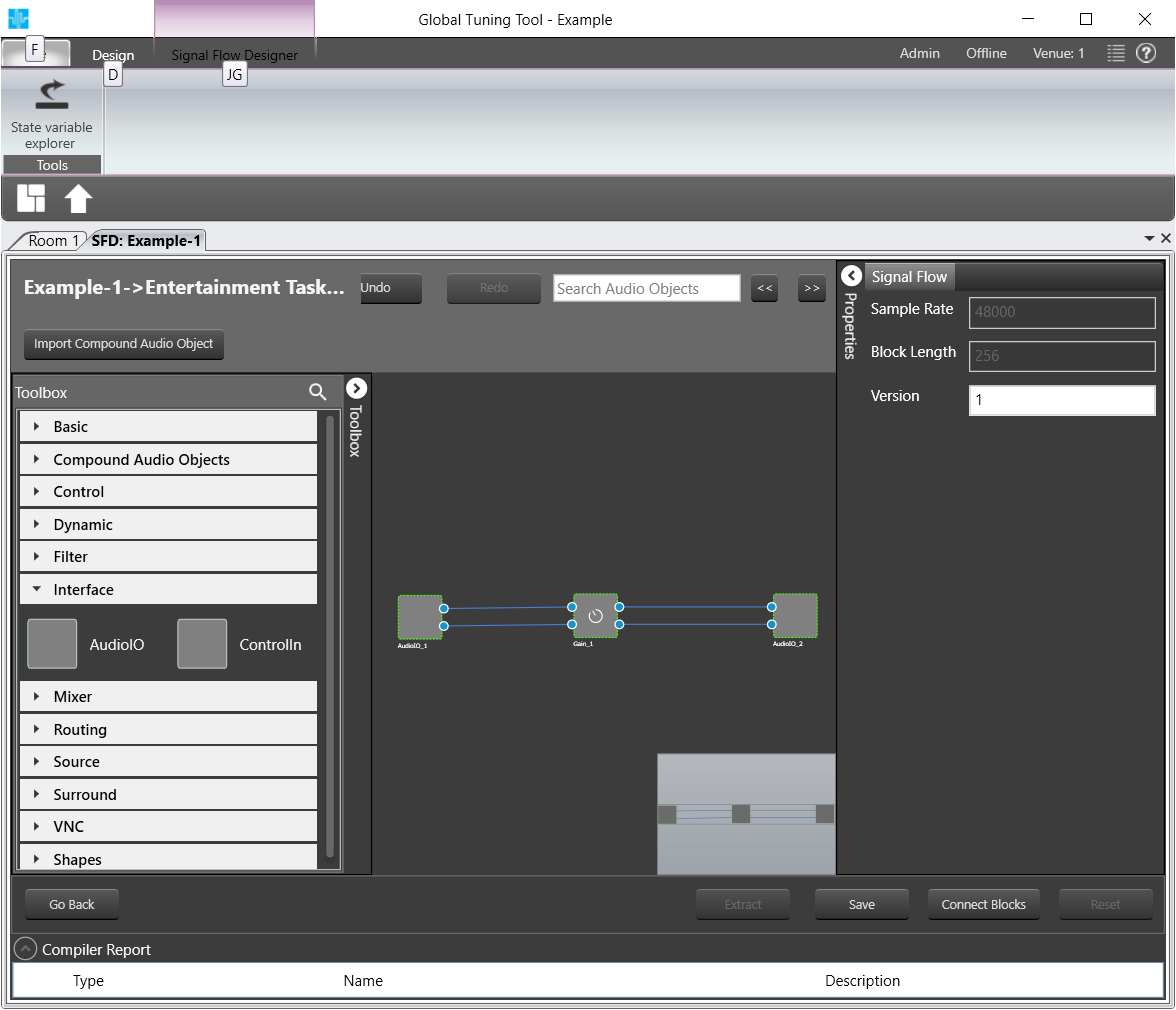
Click on Save.
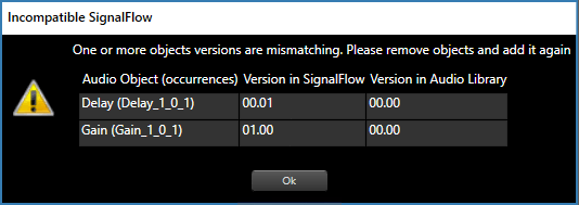
If there is a version mismatch between the current audio library version and version data present in the device, a warning message pops up asking to continue or stop saving
if there is Tuning version mismatch between Audio objects of signal flow and audio objects in tool box then warning message pops up showing tuning version differences and those audio objects are shown in blue color . Only after manually replacing these audio objects saving of signal flow is allowed.
If there is a mismatch between Sample Rate/ Block Length then a message pops up asking to continue or stop saving
Click on Go Back.
Click on Send Signal Flow.
The message Signal flow successfully submitted will be displayed.
The Signal Flow has been sent to the virtual amplifier.
Auto-Connect Feature
For complex audio blocks that support multiple channels it might be time consuming to create connections manually. The auto-connect feature is there to facilitate that task.
Select at least two audio blocks (with CTRL key pressed) and push the Auto Connect button at the bottom of the screen.
The connections between the selected blocks should be created automatically.
The signal flow can be exported to .set file by clicking Export button at the bottom of the device in Signal Flow Designer. One .mcd file will be generated for master control data and one .Signal Flow Designer file will be generated per instance per core.