
1.Overview
This guide provides an overview of the design, requirements and architecture of the feature that can modify the interfaces, definition, and requirements of the Signal Forge application.
This application is used to route data (primarily control signals) from various sources to various destinations. A common example is extracting an engine parameter from a CAN trace (say RPM) and forwarding it to the RPM control parameter in an xAF signal for simulation purposes.
The general idea is that any Input can be connected to any Output. The user controls the routing and can have as many active signals as they want/need. The system can be easily expanded (in code) by adding a new Input or Output if there is a need.
Additional this guide will cover the basic usage of the Signal Forge application. Most specifics related to fields or controls are located within the app itself (hover-over tooltips) but the theory and general usage will be covered here.
On the application window you can manipulate signal via add signal option or you can set up preference configuration. The config menu gives you control over your sessions. You can load settings from a previous saved session, and the application will remember your most recent choice.
By default, the last saved or loaded settings will be applied.
Acronyms
- xAF: Extendable Audio Framework
- xTP: Extendable Tuning Protocol
- GTT: Global Tuning Tool
- DDF: Device Description File
- SFD: Signal Flow Designer
- Offline Storage : Persistent memory
2.Woking with Signal Forge
This workflow example of Signal Forge application will give you brief idea about the concepts apply to more complicated Inputs and Outputs.
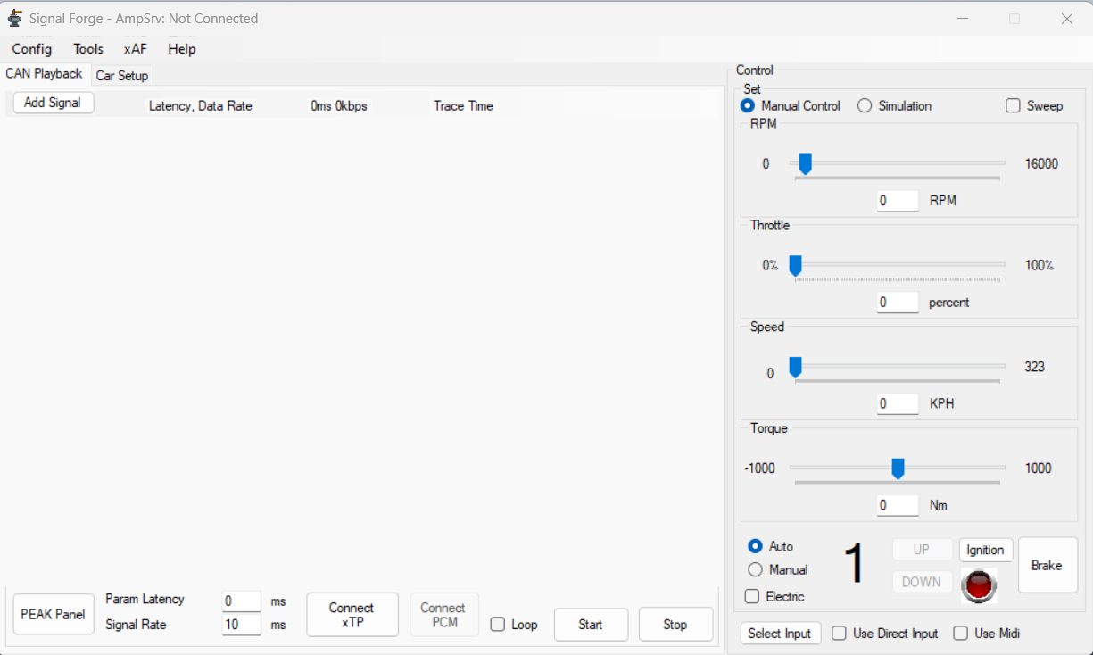
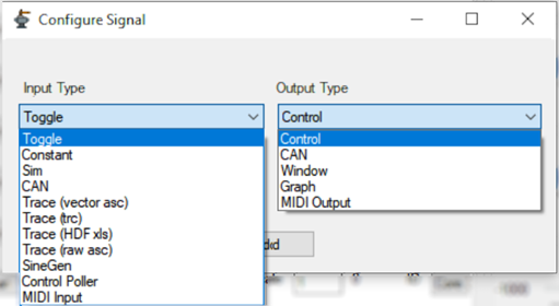
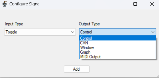
- On the Signal Forge application, click Add Signal. This will open configure signal window.
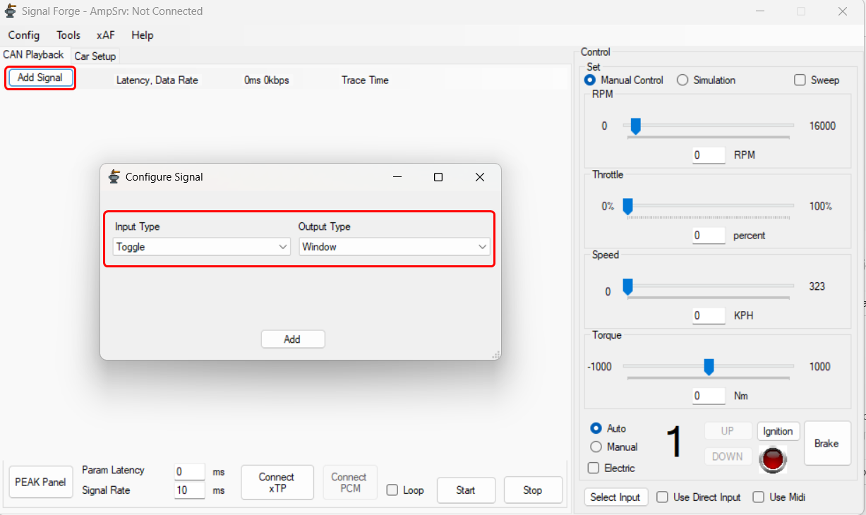
- On the Configure Signal window, set the Input and Output type from the drop-down list, and click Add.
For more details about input and output type signal, refer to Input Type and Output Type.
In the below example, the Toggle set as the input and Window set as output.- Toggle is a simple on or off switch that can send a zero or one.
- Window is more of a debugging output which can show the value of whatever input it is receiving.
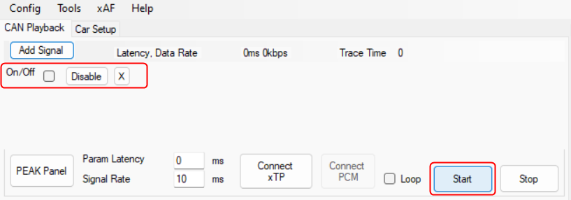
- The added signal dsiplayed on the Simulation window. This won’t do anything because processing hasn’t started yet.
- Clicking Start will initate the processing.
- Once you click “Start” a new window appears showing the value zero and the “Start” option turns to “Pause”.
- If you select the checkbox for the added signal dsiplayed on the application window, the value in the sub window updated to 1.
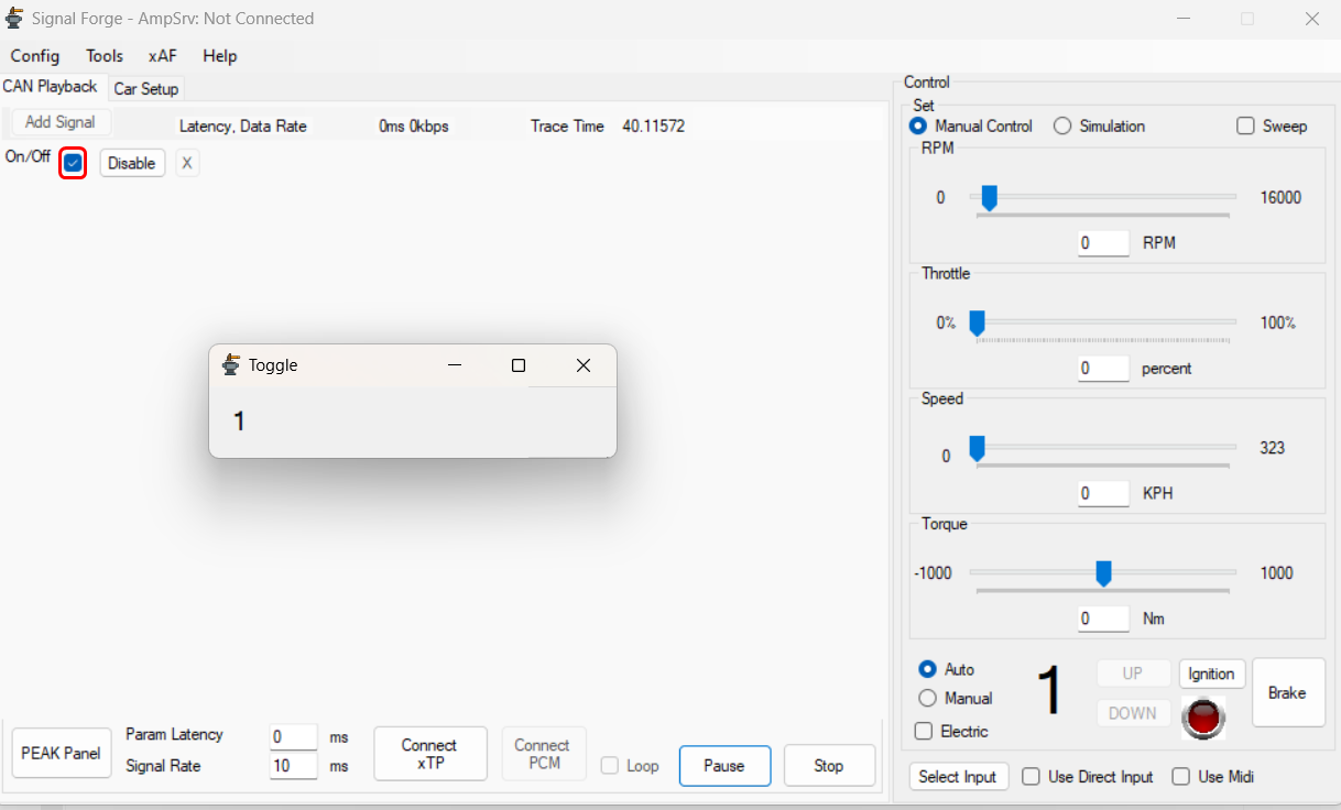
This is how signals work in this application, the input forwards a value to the output.
In general the inputs and outputs are more complicated than this simple example. For more details about input and output, refer to Signals. - Click Pause to stop processing, but keep your position in the case you are running through a pre-recorded trace input.
If you click Stop, it will stop processing and reset everything back to initial conditions. Pause will have no effect on realtime signals which don’t rely on a file, they will stop processing but will just ignore all input until resume is hit.
3.Configuration
This section describes the configuration parameters the user can set in Signal Forge.
3.1.Preferences
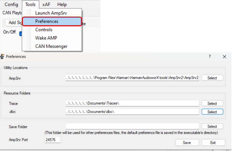
None of these are required, but they might make your use of the tool easier.
- AmpSrv: Path to AmpSrv2.exe which the tool can launch for you when connecting to an xAF virtual device. This will only be launched if the process is not currently running.
If the process is running but set to a different port, you will need to manually launch and configure another instance of AmpSrv before connection will succeed.
- Trace: Path that will be your start location when choosing a trace file for a signal (eg .asc, trc, xls).
- .dbc: Path that will be your start location when choosing a DBC file (for live CAN or a CAN trace).
- Save Folder: Not required, but if you want to save your config in a special location you can use this.
- AmpSrv Port: When we connect to a virtual device we will look for AmpSrv connections on this port.
3.2.Saving and Loading

Vehicle: This file saves all settings related to the actual vehicle simulation parameters located in the Car Setup tab.
Comms: This file saves :
- All the signal information (all your added signals and their properties).
- Control ID list imported (Tools > Controls).
- Signal Rate and Latency (Latency is not currently used, it was used to synchronize controls with audio, which is not possible currently).
Input: This file saves all settings related to MIDI or Direct input controls for the simulation. (e.g. pedal for throttle)
3.3.Playing

Start/ Stop: Use the Start and Stop button on the panel to play pause and stop playback. Nothing will output while in the stopped state, and pause will keep you at the position you are at in a trace file but stop output.
Signal Rate: The Signal Rate field for controlling output rate of things like xTP Controls.
Loop: Loop will cause fixed duration traces to restart after they reach the end.
Connect xTP: Connect xTP connects you to an xAF device via AmpSrv, allowing you to use its related features.
Many configuration options are disabled in the playing stage for compatibility reasons.
4.Signals
This is the core of the program. There are multiple input sources and multiple outputs, when you pair an input and output then you’ve created what is called a signal.
4.1.Inputs
Inputs provide data to outputs for processing. They can be realtime sources or files that playback pre-recorded sequences.

Toggle: Simply a checkbox, disabled is 0, enabled is 1.
Constant: Input a value that is convertable to float32 and it will be output continually.
Sim: This input uses the simulation component which can be configured via the Car Setup tab. Note this input is not completed and does not quite perform as expected but can still be used to generate interesting signals to test with, they just don’t behave physically accurately.
- RPM – Current RPM of the engine
- Torque – Current Torque output of the engine (not transmission)
- Throttle – Current throttle input of the engine.
- Speed – Current speed of the vehicle
- Gear – Current gear – output continually not on change
- Gear Up – fires once when gear is changed up
- Gear Down – fires once when gear is changed down
- Engine Start – fires once when engine starts
- Engine Stop fires once when engien stops
CAN: Uses the PEAK PCAN device. Realtime CAN connection using PEAK sdk. Configure using the PEAK Panel button – configuration not covered here. You also need to load a DBC file for the network you are connected to. After this you can get all instances of the selected parameter, when they come in.
Traces: Grouped together for easier explanation. These all load recorded or generated files and play through them according to an internal timer. All these files have timestamps associated with parameters and those are used to determine when a parameter is output. The user will select which (of potentially many) parameters in the file is used for a given signal. The file can be loaded into multiple signals at once (its only loaded by the application once) so the user can select multiple parameters from a single file.
Trace (vector asc): Vector CAN export. This signal also needs a DBC file loaded in order to be parsed. Note that its possible to have a mismatching DBC file that still matches ID’s in the trace. Be sure they REALLY match or your outputs will make no sense.
Trace (trc): Peak CAN export. This signal also needs a DBC file loaded in order to be parsed. Note that its possible to have a mismatching DBC file that still matches ID’s in the trace. Be sure they REALLY match or your outputs will make no sense.
Trace (HDF xls): Excel file created by Head Acoustics software. This can easily be generated by the user as well.
Trace (raw asc): Raw ascii file also exported by Head Acoustics. This file has no metadata, so it isn’t very fun to work with.
SinGen: Generates a sine wave with the magnitude specified and an offset of 0. Phase offset can be applied.
If you use the Dynamic mode, then the frequency setting becomes a ratio of the selected signal INPUT (not output). The indices start at zero.
Control Poller: Requests the value of a control from a connected xAF device. Uses the loaded list of controls (Tools->Controls) to display the available controls. Has a configurable polling period which defaults to 10ms.
MIDI Input: Uses detected MIDI devices. User needs to select a device, and a type of event (Note On, Note Off, Control Change, and None).
- Note On: Sends Fires while the note is active, else 0.
- NoteOff: Fires a when the note ends, else outputs 0.
- ControlChange: Fires on any change of a control.
- None: Nothing.
For each of these types you will get an associated list of sub-types. For notes you get piano keys, for controls you get a list of some named control types but many numbers. You will have to discover which match your device’s controls. You can use the Input section (‘Select Input’ -> ‘Midi’ then look at ‘Real-time data’) to see control messages as they come in from the device.
Since MIDI is only 0-127 – we have scaling (multiplying) and offset (adding) fields so you can move the value into a useful range. Scaling is applied first. E.g. input value of 10 from midi. Scale is 20 so the value becomes 200. Offset is -40 so the value becomes 160.
4.2.Outputs
Outputs consume Inputs. Whereas Inputs provide data as their function, the output will actually use the data to do something. The data could be displayed or sent somewhere or otherwise processed.
Control: Sends a control message to a connected xAF device, at the rate set by the Signal Rate parameter at the bottom of the panel.
All control outupts will be grouped together in a single message if possible. They all run and then at a final stage they are grouped and sent.
CAN: Opposite of the input CAN but with the same usage. Configure the panel, select a DBC file, select a parameter to encode to.
Window: Show the output value in a floating window.
Graph: Show the output values in a scrolling graph. You can scale the input values by a value, if its useful.
MIDI Output: Opposite of the MIDI input, see “MIDI Input” in Input section for usage. The scale and offset parameters are still scaling first, offset second. You should fit your data into the 0-127 range.