FIRA MIMO audio object is a group of FIR filter banks associated with each input and output. FIRA stands for “fir accelerator” and it indicates that the underlying implementation uses a hardware accelerator. MIMO stands for “multi input multi output” indicating that each output is the summation of one or more FIR filtered inputs.
FIRA MIMO can be used for various applications like individual sound zones etc.
Use Case: This audio object can be deployed whenever the audio requires the dual rate MIMO FIR filters taking into considerations the data pipeline delay and other limitations. More than one instance of FIRAMIMO also can be run in the same core .
The AO supports in-place computation based on the core type.
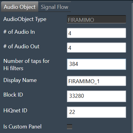
FIRA MIMO Properties
| Properties | Description |
| # of Audio In |
Enter the input value. Range: 1 to 20 The default value is set to 4. |
| # of Audio Out |
Enter the output value. Range: 1 to 64 The default value is set to 4. |
| Number of taps for Hi filters |
The number of filter coefficients (taps) for the high rate path is configured using the m_NumElements. All channels in the high rate path use the same number of taps. Range: 384 to 4096 The default value is set to 384. |
| Display Name | Display name of the FIRAMIMO audio object in signal flow design. It can be changed based on the intended usage of the object. |
Mode
There are no modes available for FIRA MIMO.
Additional Parameters
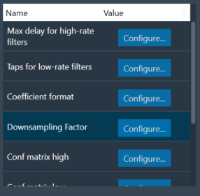
Below table describes the FIRA MIMO additional parameters.
| Parameter | Description | |
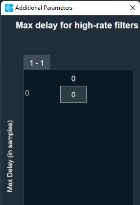
| Max delay for high-rate filters |
Length of delay line for high-rate path. Range: 0 to 2048 Default: 0 Data Type: uint32_t |
 |
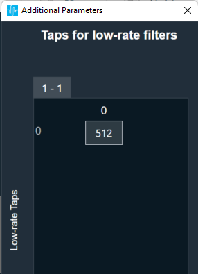
| Taps for low-rate filters |
Number of taps for low-rate filters. All channels in the low rate path use the same number of taps which can be different from high rate. Range: 512 to 2048 Default: 512 Data Type: uint32_t |
 |
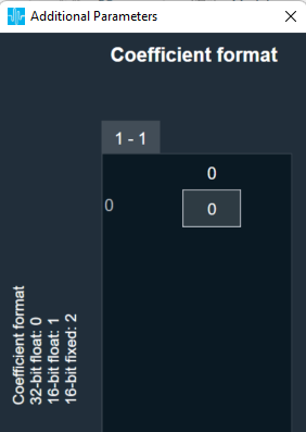
| Coefficient format | Filter coefficient data format.
Range: 0 to 2 Default: 0 Data Type: uint8_t |
 |
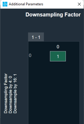
| Down sampling Factor | Down sampling factor.
Range: 0 to 1 Default: 1 Data Type: uint8_t
|
 |
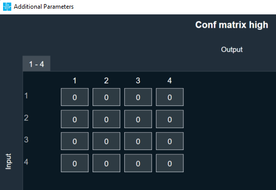
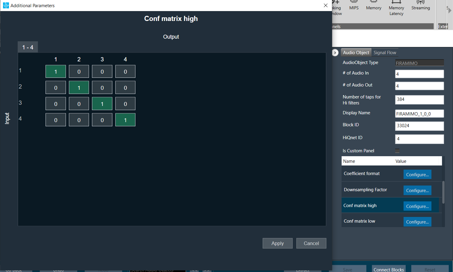
| Conf matrix high | Configuration matrix for high rate filters.
Value:
Range: 0 to 1 Default: 0 Data Type: uint8_t |
 |
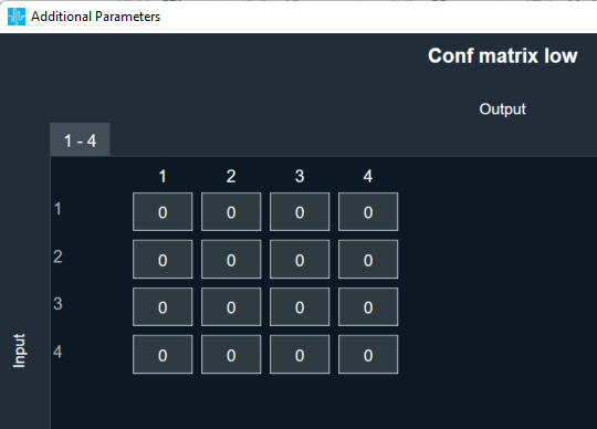
| Conf matrix low | Configuration matrix for low rate filters.
Value:
Range: 0 to 1 Default: 0 Data Type: uint8_t |
 |
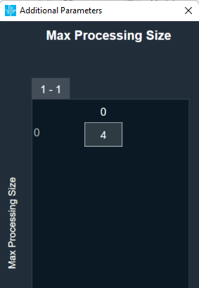
| Max Processing Size |
When 2 or more filters are enabled on an input channel, FIRAMIMO combines them and submits as one job to the accelerator. Max Processing Size is used as the max limit when combining. For example, when there are 6 filters enabled on an input channel and Max Processing Size is set to 4, FIRAMIMO submits first job for 4 filters and second job with 2 filters. Range: 2 to 8 Default: 4 Data Type: uint8_t |
 |
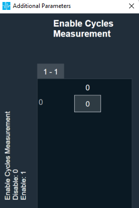
| Enable Cycles Measurement | Enable/Disable realtime accelerator mcps (million cycles per second). When enabled, Average and Max mcps available to be read as tuning parameters in sate variable explorer.
Range: 0 to 1 Default: 0 Data Type: uint8_t |
 |
| Accelerator Configuration | Select which among the available FIR hardware accelerator to use for the FIR processing.
Range: 0 to 2 Default: 0 Data Type: uint8_t On ADSP-21593, when this configuration is set to Accelerator 1, only the first accelerator will be used, when set to Accelerator 2, only the second accelerator will be used, and when set to Both Accelerators, both available FIR accelerators will be used with almost equal number of filters processed by both accelerators. When both hardware accelerators are used and “enable cycles measurement” additional configuration is enabled, the average and maxixmum mcps of both the accelerators shall be individually readable from the SV explorer. On DSPs with only a single accelerator such as the ADSP-21569 (GUL), selection of accelerator configuration will be available, however, all filtering jobs will be processed by the only available FIR accelerator.
|
|


Tuning Parameters
For each filter combination in FIRA MIMO, this object exposes these two tuning parameters to the GTT:
Mode: The mode of each filter can be set to:
- Normal
- Bypass
- Off
This parameter is of the category “State” and therefore, the configurations done for Filter modes will be transferred to the device only after the device is connected.
Coefficients: Filter coefficients can be imported from .csv files. The filter taps set in the GTT must match the taps of the filter being imported from the .csv file.
Control Parameters
There are no control inputs.
Native Panel
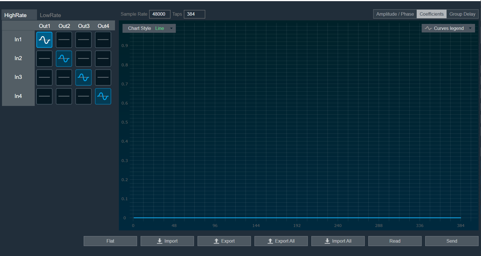
FIRA MIMO native panel allows you to configure the Mode of each enabled filter and to load coefficients as well. All the diagonal filters are active as this diagonal values are configured through additional parameters. In order to see the graphs, you need to import coefficients. Use ‘Import’ or ‘Import All’ option to import coefficients.
To open the native panel, double-click on the FIRMIMO audio object in the signal flow designer.
When the device is connected the filter states will not be in sync with the device until the states are received or the native panel is opened. Once the native panel is opened after a successful connection, the filter states will be transferred to the device.
Provide number of Taps to 384 and from additional parameters set all diagonal cell to 1 for Conf matrix high/ low as per below image.
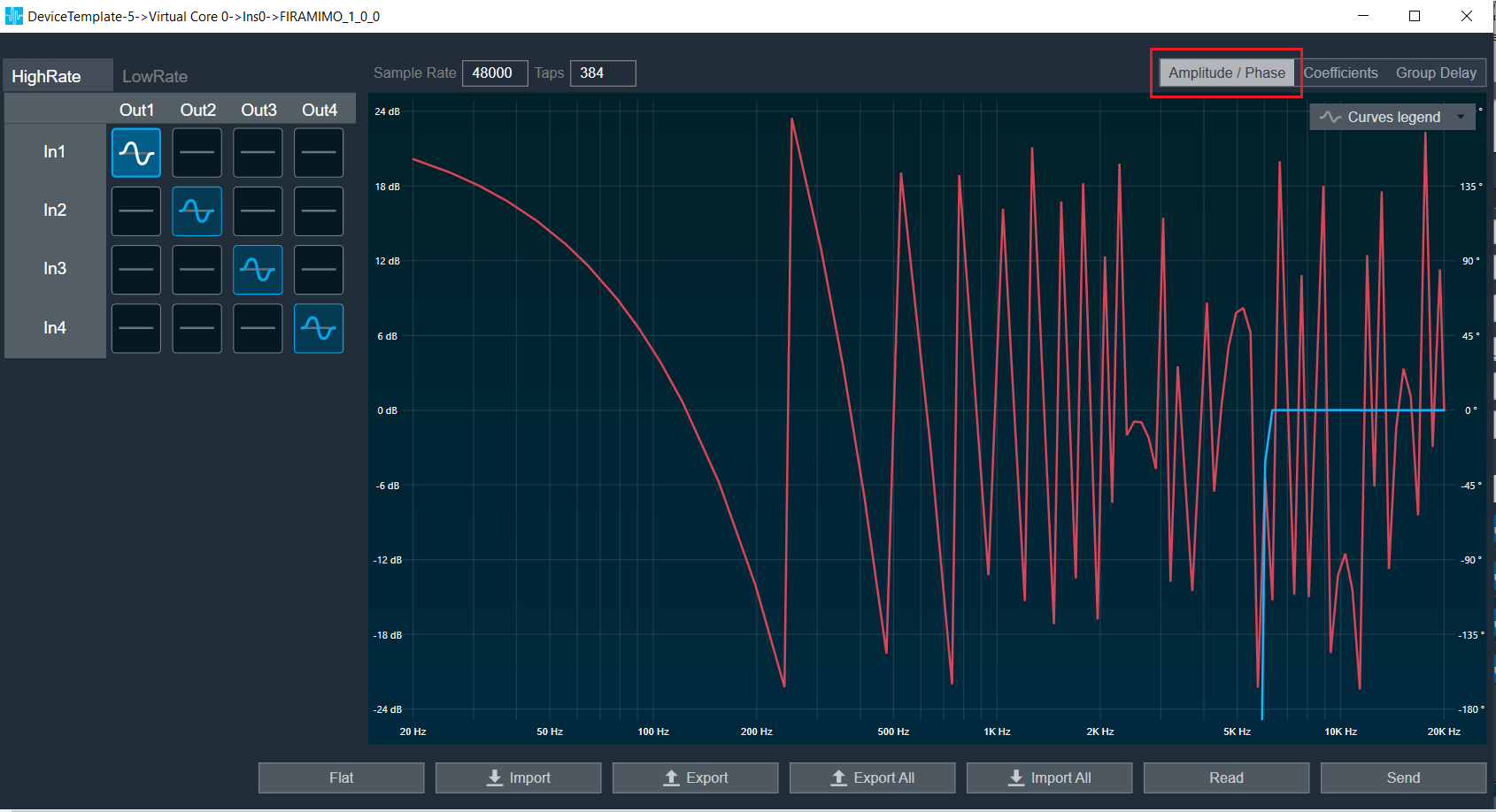
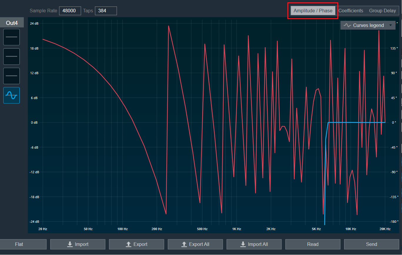
Amplitude/Phase: When the coefficients are given and “Amplitude/Phase” option is selected, the graph display the value as per below figure.
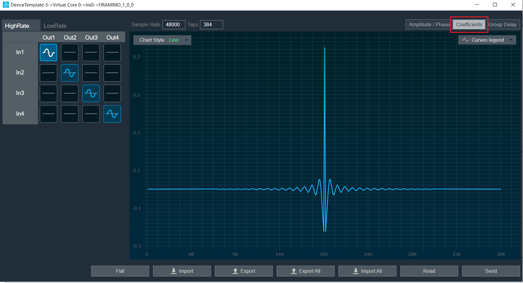
Coefficients: When the coefficients are given and “Coefficients” option is selected, the graph display the values as per below figure. You can change the graph style using “Chart Style” option.
- Line chart style: when “Chart Style” selected as Line, the Coefficients graph as per below image.
- Dot chart style: when “Chart Style” selected as Dot, the Coefficients graph as per below image.

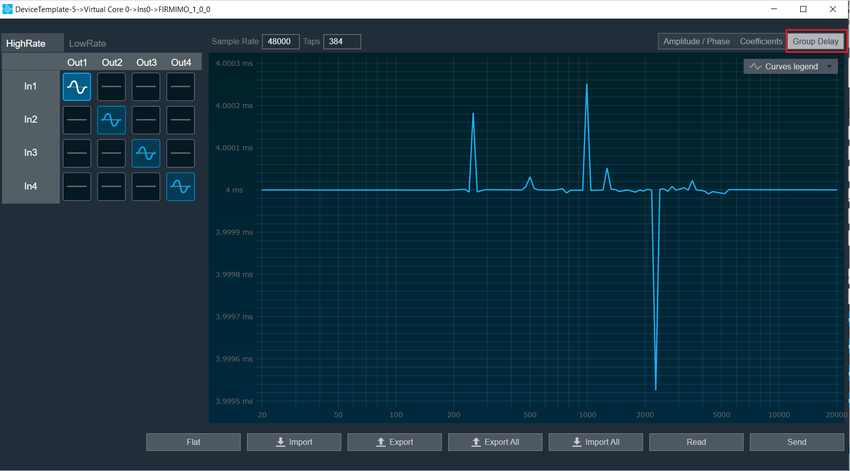
Group Delay: When the coefficients are given and “Group Delay” option is selected, the graph display the values as per below figure.
Curves Legend: This option allows you to show the details of which graph tab (Amplitude/Phase, Coefficients, Group Delay) is selected.
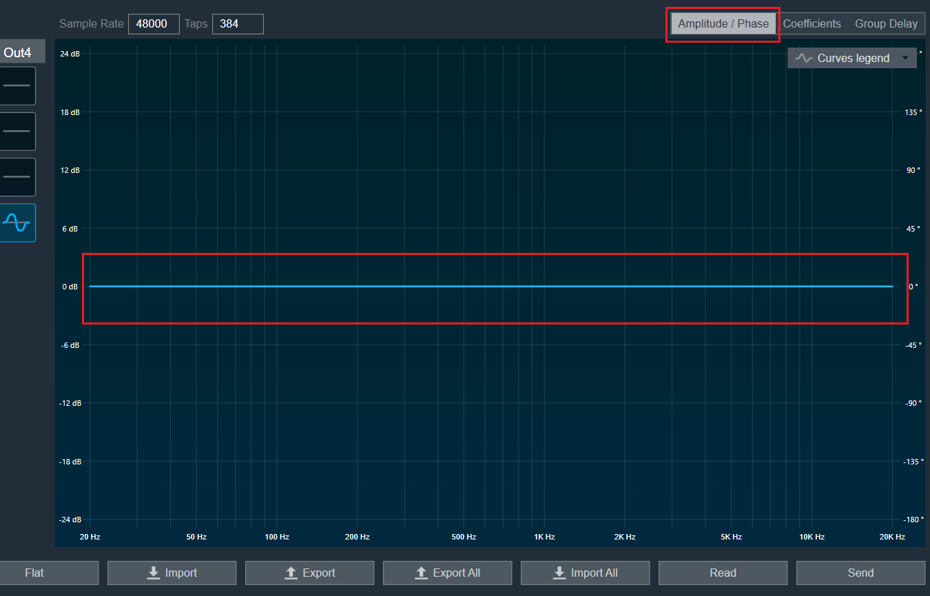
On the selection of Amplitude/Phase graph tab Curves Legend will show below information.

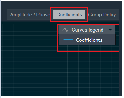
On the selection of Coefficients graph tab and Chart Styles ‘Dots’, Curves Legend will show below information.
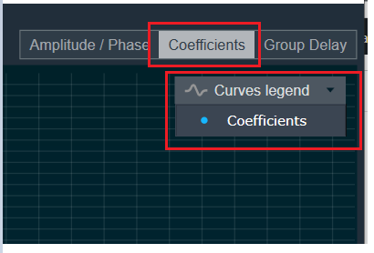
On the selection of Coefficients graph tab and Chart Styles ‘Line’, Curves Legend will show below information.
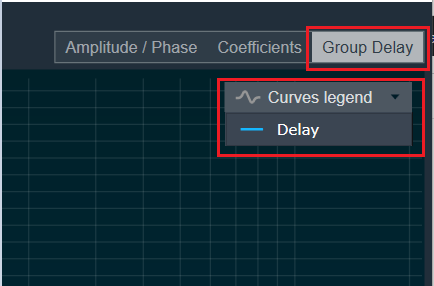
On the selection of Group Delay graph tab, Curves Legend will show below information.
Additional Functionalities
Flat : This is used to make the graph flat by making coefficients to 0.
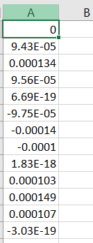
Import : This function is used to import the coefficients for a single active filter. Click the “Import” button, then enter the file path and click Ok.
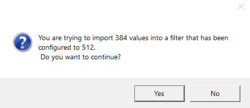
All coefficients for the selected filter will be imported, as shown in the graph. If the number of coefficients does not match the number of taps as shown in the screenshot below, a warning pop up will appear.
Click ‘Yes’ to import available coefficients or click ‘No’ to cancel the import.
Export : This option is used to export coefficients for selected active filter into csv file.
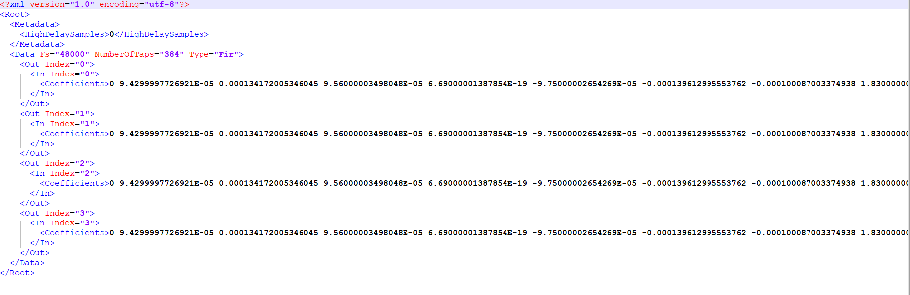
Export All : This option is used to export all active filters in one go. Click the “Export All” button, then enter the path and file name, then click Ok.
A xml file will be created which will have coefficients for each active filter. Below figure shows the example of the configuration of the active filters in the xml file.
You can use Import All’ button to import back the exported file.
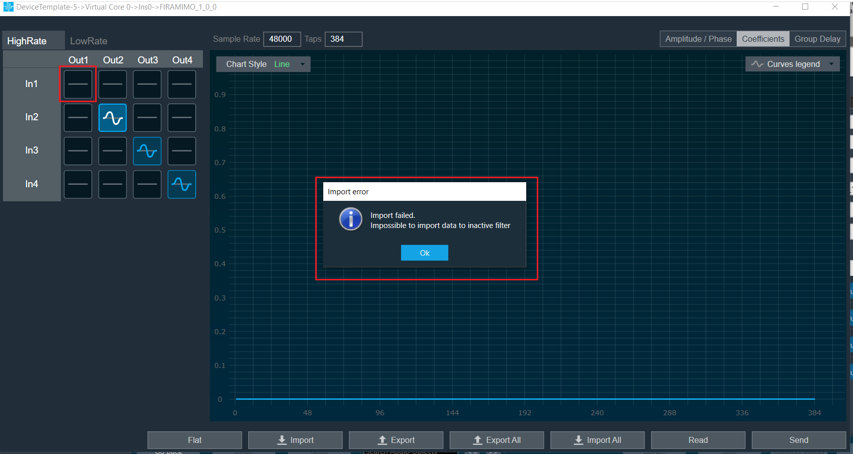
Import All : This option is used to import all coefficients in one go. Click the “Import All” button, then enter the XML file path and click Ok.
All the given coefficients will be imported and can be seen in the graph. If there is a mismatch between xml file In and Out matrix with FIRMIMO panel In and Out matrix then error will be displayed and import will fail.
In below image filter (Out 1 In1) is not active and try to import this as well so error is prompted.
Read: This is used to read from the target to display in the panel.
Send : This is used to send the values changed in panel to target.
Above mentioned functionality is similar for LowRate tab as well.
Memory Record Management for SHARC ADSP-21593 in Dual Accelerator Mode
When using the FIRAMIMO object on a SHARC ADSP-21593 in dual accelerator mode, careful memory record placement consideration is required to maximize the number of FIR filters that can be processed. The hardware FIR accelerators in the DSP perform operations in parallel with the cores, causing memory access bottleneck due to the increase in the number of parallel memory accesses to the external memory (DDR3). This can be attributed to the page management overheads incurred by the Dynamic Memory Controller (DMC) as described in the EE-412 document, which adversely impacts the FIR accelerator performance, limiting the total number of FIR filters that can be processed by the AO. In order to mitigate the issue and improve the processing capacity of the accelerators, it is recommended that the input, output and filter coefficient buffers accessed by each accelerator are placed in dedicated DDR3 memory banks.
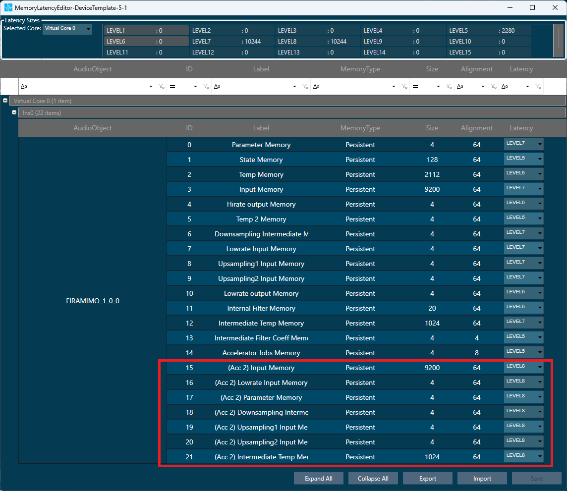
To enable placement of the buffers in separate banks, when the “Accelerator Configuration” additional configuration parameter is set to 2 (Both Accelerators), a new set of additional memory records with the prefix “(Acc 2)” are created to accommodate the second FIR accelerator’s input, output and coefficient buffers. The following figure shows the Memory Latency window in GTT highlighting the newly created memory records:
In this configuration, following are the memory records accessed by the accelerators:
| Hardware FIR Accelerator 1 | Hardware FIR Accelerator 2 | Description | |
| 1 | Input Memory | (Acc 2) Input Memory | High rate input buffers |
| 2 | Lowrate Input Memory | (Acc 2) Lowrate Input Memory | Low rate input buffers |
| 3 | Parameter Memory | (Acc 2) Parameter Memory | Filter coefficient buffers |
| 4 | Downsampling Intermediate Memory | (Acc 2) Downsampling Intermediate Memory | Downsampling filter output buffers |
| 5 | Upsampling 1 Input Memory | (Acc 2) Upsampling 1 Input Memory | Stage 1 upsampling filter input buffers |
| 6 | Upsampling 2 Input Memory | (Acc 2) Upsampling 2 Input Memory | Stage 2 upsampling filter input buffers |
| 7 | Intermediate Temp Memory | (Acc 2) Intermediate Temp Memory | Temporary memory for coefficient format conversion |
As per the recommendation, notice in the above figure that the memory records accessed by accelerator 1 are all placed in Level 7 memory latency, and the memory records accessed by accelerator 2 are all placed in Level 8 memory latency. It is expected that the platform maps these memory latency levels to un-cached memory regions that are in separate DDR3 memory banks in order to fully realize the separation of buffers.
At 512 sample block length, with 2k-tap high rate filters, following are the improvements observed in the total number of filters that can be processed by the FIRAMIMO AO in single vs dual accelerator modes:
- All accelerator buffers placed in Level 5 latency: 20% (32 filters to 40 filters)
- Accelerator 1 buffers in Level 7 and accelerator 2 buffers in Level 8, mapped to separate DD3 banks: ~90% (32 filters to 60 filters)
It is important to note that the separation of the memory records for the hardware FIR accelerators, however, increases the core MIPS consumption by about 30-60% in both single and dual accelerator modes due to additional buffer movement and summation operations done by the core to reduce the memory access overheads.