
1.Overview of Gear Shift Simulator
The purpose of Gear Shift Simulator is to simulate gear shift in an electric vehicle, focusing on simulating the RPM behavior during gear shift.
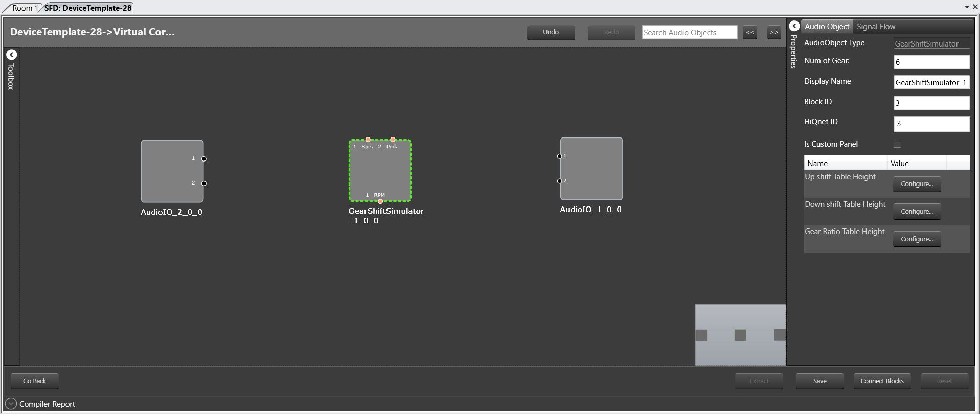
It contains two control inputs: vehicle speed & pedal position, and one control output: RPM.

Gear Shift Simulator native panel can be launched from signal flow designer and system function.
2.Build design time parameters
Following parameters can be configured during design time,

| Configuration Parameter | Range | Note |
| Num Of Gear | 1-16 | Number of simulated gears |
| Up Shift Table Height | 2-128 | Table height of up shift table |
| Down Shift Table Height | 2-128 | Table height of down shift table |
| Gear Ratio Table Height | 2-128 | Table height of each gear ratio table |
The above mentioned parameters are using for constructing structure of state variables in Gear Shift Simulator.
3.Gear Shift Simulator Panel

Gear Shift Simulator Panel has three groups of parameters to configure,
- General Parameters
- Gear Shift Table
- Gear Ratio Table
General Parameters
The following parameters are grouped under “General Parameters” tab in the panel,
- Speed Smooth Coefficient – Float value ranges from 0 to 1 and default value is 0.0
- Pedal Smooth Coefficient – Float value ranges from 0 to 1 and default value is 0.0
- RPM Smooth Coefficient – Float value ranges from 0 to 1 and default value is 0.0
- RPM Out Ratio – Integer value ranges from 0 to 100 and default value is 1.
RPM Out Ratio will be converted in ms using below formula :
1000 * RPM Output Ratio * Block Length / Sample Rate varies with the value of “RPM Output Ratio”

The values can be configured by using the slider/by directly entering in the textbox/by clicking the increment or decrement buttons.
Speed & Pedal smooth coefficients are using in smooth function to smooth control inputs: pedal position and vehicle speed.
Gear Shift Table


Two sub tabs are present in Gear Shift Table tab – “Up Shift & Down Shift”. In both of these sub tabs, following parameters can be configured,
- N Pedal values – Float value ranges from 0 to 100 and default value is 0.0
- N * M-1 Gear Shift values – Float value ranges from 0 to 512.0 and default value is 0.0
Pedal values & Gear Shift values are arranged in a table with N number of rows and M-1 number of columns to configure easily. Where N is the value of table height parameter[Up Shift Table Height /Down Shift Table Height] and M is the value of number of gear parameter.
Gear shift table defines up& down shift lines depending on the vehicle speed and pedal position.
Gear Ratio Table

In Gear Ratio Table tab, N number of sub tabs are present, where N is the value of “Number of Gear” parameter. Following parameters can be configured under each of these sub tabs,
- N Speed Values – Float value ranges from 0 to 512.0 and default value is 0.0
- N RPM Values – Float value ranges from 0 to 16000 and default value is 0.0
The parameters Speed Values & RPM Values are arranged in a table with N number of rows and 2 columns to configure easily. Where N the value of “Gear Ratio Table Height” parameter for each gear.
Each gear ratio table is provided as a two-dimensional array, called an “xy-map” with n points. The x value represent Speed value (km/s). It is assumed that for all points, the x values are ascending. For each x value there is a corresponding y value representing the RPM value. Each table represent how the RPM changes with speed under specific gear.
From both Gear Shift Table and Gear Ratio Table tabs, parameter values can be auto send to device by checking “Auto Send” check box. Modified values can be sent to device explicitly by clicking “Send” button. Values from device can be read by clicking “Read” button.