
1.Overview
The Measurement Module is used to perform synchronous and asynchronous impulse response measurements, and recordings.
If you want to work with Measurement Module, you don’t need an active project. GTT will automatically create dummy project, where you can perform all the operations. In case there is active project available, the Measurement Module session will be associated with it.
A device is not necessary for the Measurement Module to function in the project. The Measurement Module enables direct sound card measurements without an intermediate device, whereas tests controlled by gain channels can be carried out via a device.

2.Measurement Module Ribbon Bar
The Measurement ribbon consist of the following groups.

- Import/Export: Using Import and Export option you can configure the import and export setting of measurement module. For more details refer, Import and Export Settings.
- Reset All: Using “Reset All” option you can reset parameters used for the measurement setup (scene, speaker mapping, mic mapping, and measurement session).
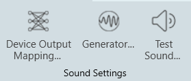
- Sound Settings: In the Sound Settings group you can configure Device Output Mapping, Generator, and Test Sound settings. For more details refer, Sound Settings.
The entire ribbon bar will not function once a measurement session is active, it will re-function after it ends, since the settings made here do not affect an active measurement session.
2.1.Import and Export Settings
Import MM IR Setting
The import menu allows you import of parameters available in the specified file.
Following are the parameters you can import.
- Chosen scene
- Device output mapping
- Configured speakers
- Configured microphones
- Defined measurement sequences
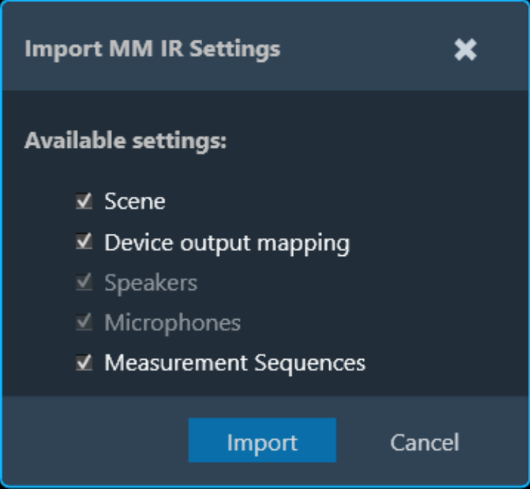
These settings can be imported individually or together. Only the selection of the sequence import forces the import of speakers and microphones to guarantee consistency.
The import for the device output mapping will throw a warning, if the project does not match the original project.
Export MM IR Settings
The export allows you to export of all setup related parameters.
Following are the parameters you can export.
- Chosen scene
- Device output mapping
- Configured speakers
- Configured microphones
- Defined measurement sequences
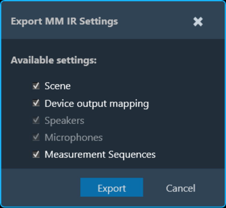
These settings can be exported individually or together. Only the selection of the sequence export forces the export of speakers and microphones to guarantee consistency upon re-import.
2.2.Sound Settings
In this group you can configure Device Output Mapping, Generator, and Test Sound parameters. These menus are accessible during every step of the measurement preparation.
2.2.1.Device Output Mapping
The device output mapping menu allows for the mapping of gain channels to device output channels.

The names of the available devices in the room are displayed in the first column (red rectangle below), together with their device output channels in the second column (yellow rectangle).
The available gain objects can be assigned in the third columns (green rectangle), together with their respective gain channels in the fourth column (blue rectangle).
Currently, it is the users responsibility to re-create the same connections as in the Signal Flow Designer to ensure the expected functionality.
The assignment of the first gain device will trigger an auto-completion of the entire list. This behavior can be disabled by unchecking the checkbox in the lower left corner of the menu.

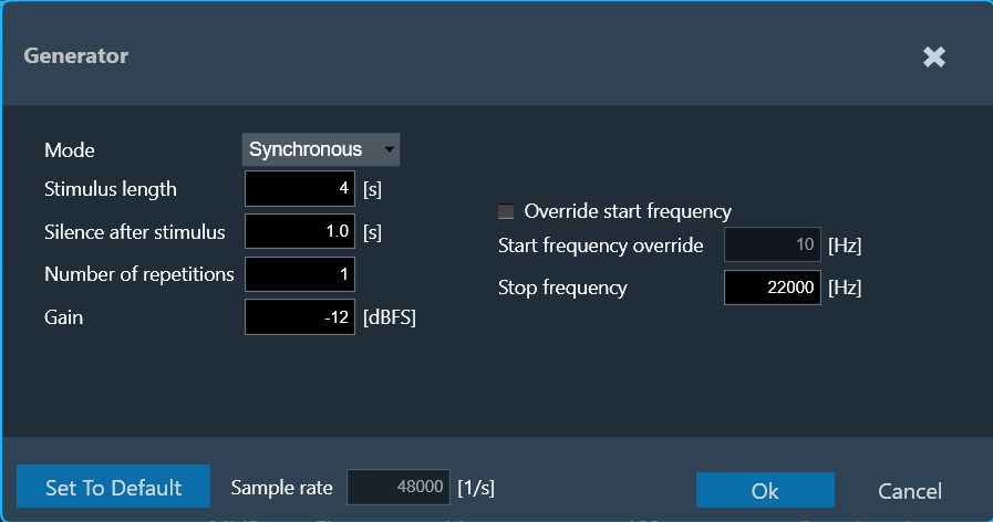
2.2.2.Generator
The generator menu is used to define parameters for the signal used in measurements. Using drop-down option you can select Generator mode.
Generator supports following mode.
- Synchronous” (for synchronous IR measurements)
- Asynchronous” (for asynchronous IR measurements)
- Recording
Synchronous Mode
The following parameters can be set in synchronous mode:
- Stimulus length: Duration of the signal in seconds used to measure.
- Silence after stimulus: Stop margin after end of playback, to capture the tail of the sweep signal also in very reverberant environments or over long distances. Takes decimal values.
- Number of repetitions: Number of measurements tool will do, used for average measurement.
- Gain: Playback gain in dBFS, only integers can be specified, positive values will be correct to negative.
- Override start frequency: If checked, the value entered for “Start frequency override” takes precedence over individual loudspeaker settings on the speaker configuration tab
- Start frequency override: Lowest frequency of the sweep. Only enabled if Override start frequency enabled.
- Stop frequency: Highest frequency of the sweep. The value will be hard limited to 1/2* sample rate
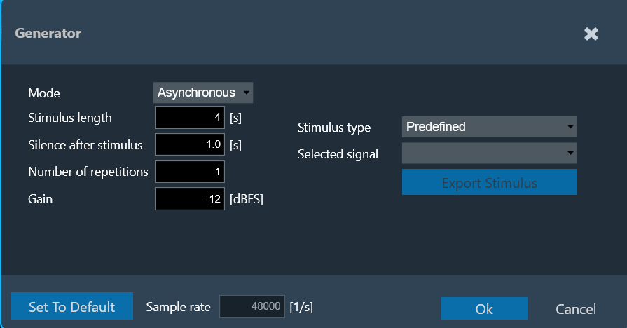
Asynchronous Mode
The following parameters can be set in asynchronous mode:
- Stimulus length: Duration of the signal in seconds used to measure.
- Silence after stimulus: Stop margin after end of playback, to capture the tail of the sweep signal also in very reverberant environments or over long distances.
- Number of repetitions: Number of measurements tool will do, used for average measurement.
- Gain: Playback gain in dBFS, only integers can be specified, positive values will be correct to negative
- Stimulus type: Choice between “Predefined” and “External”.

For “External” Stimulus type, the following additional parameters can be set:
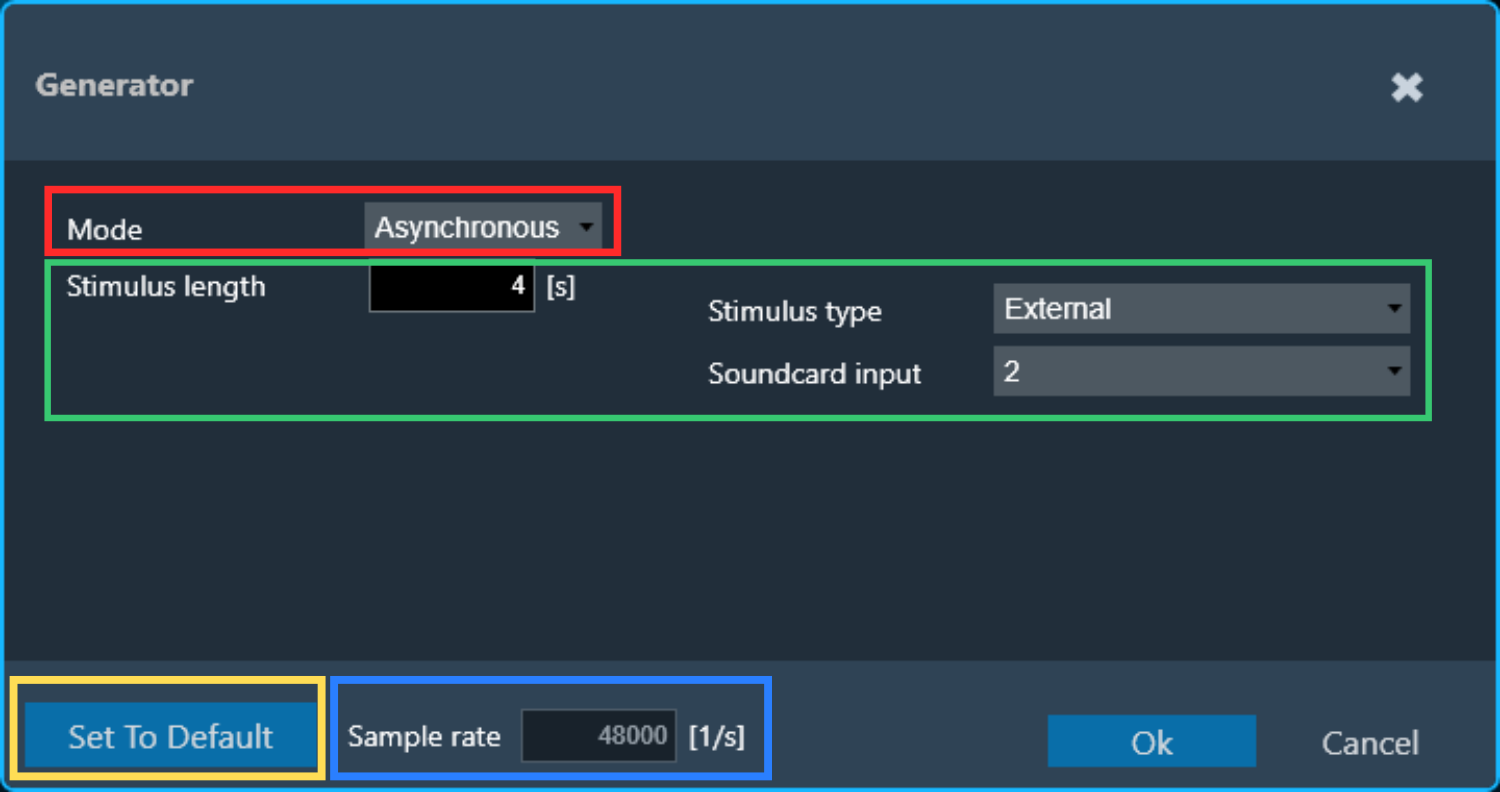
- Selected signal: Signal from signal library.
- Export Stimulus: Opens an export dialog to export the signal for manual playback according to the parameters defined in this menu.
- Soundcard input: Selection of the soundcard input used for external stimulus tracking (the measurement on this channel will be used as reference for the IR estimation). The channels specified here cannot be used as microphone input channel.
The default settings can always be recalled by clicking on Set to Default.
The Sample rate information is read only. You can “Sound Card Configuration” to modify the sample rate.
The signal library folder for predefined stimulus signals can be set under File > Options > General Settings > Predefined Stimulus Signals Folder.
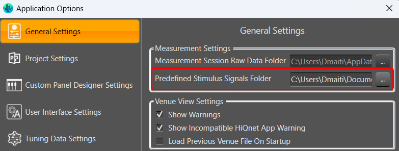
The folder needs to contain a “PredefinedSignalsDescription.csv” file specifying the details of the files, and a folder each containing the wav files all required sampling rates:

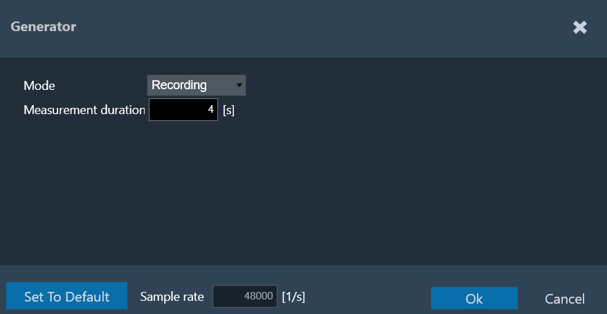
The following parameters can be set in recording mode:
Recording Mode
Measurement duration: measurement signal length in seconds for pure recordings without signal generation. The maximum recording length is 60 seconds.
2.2.3.Test Sound
The Test Sound menu is used to set the parameters for the test sound.
The test sound is available on the speaker configuration tab and serves the purpose of quickly verifying the correct connection to a speaker selected in the speaker table. A generated sweep, or one of the predefined Async measurement signals (see “Generator”) can be used for the speaker test. The playback is limited to 2 seconds.
The following parameters can be set in sweep mode:
- Gain: Playback gain in dBFS, only integers can be specified, positive values will be correct to negative

The following parameters can be set in predefined mode:
- Gain: Playback gain in dBFS, only integers can be specified, positive values will be correct to negative
- Selected signal: Choice of predefined signals

3.Measurement Walkthrough
The workflow of the Measurement Module is sequential.
- Scene Selection: Choose the scene for your measurement. This involves selecting a pre-defined scene.
- Speaker Configuration: Select speaker type and arrange the speakers position within the chosen scene. Then configure the speakers.
- Microphone Calibration: Select microphone type and arrange the microphone position within the chosen scene. Then configure the microphones.
- Measurement Sequence Definition: Define one or more measurement sequences.
- Measurement Execution: Initiate the measurement based on the defined sequences. This might involve capturing audio data from the microphones.
In the current version, the inspection of the result of the measurement, as well as all the postprocessing has to be done in the legacy MM IR module.
3.1.Scene
The Measurement Module guides through each step to perform a measurement. Select and configure a Scene
- The “Scene” screen displays various measurement scene options like a left-hand drive car with two seats or inside a room.
- Selecting a scene here impacts two things:
- The number of available microphone positions. This depends on the chosen scene like a two-seater car will have fewer microphone positions than a five-seater).
- Microphone position numbering: This is based on the driving position (left to right for left-hand drive, vice versa).

Once you double-click on the desired scene, the “Speaker Configuration” window will open.
3.2.Speaker Configuration
Once respective scene is selected, configure the speaker configuration.
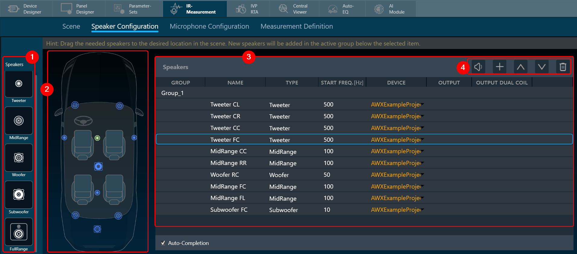
- Speaker Selection: The “Speaker Configuration” screen displays the chosen scene. On the left side, you’ll find a list of available speaker types.
- Placing Speakers: Drag and drop the desired speaker types from the list onto the scene.
Dragging a speaker far outside the scene will delete it. - Speaker List: Once placed, speakers appear in the “Speakers” list.
By default, all speakers belong to “Group_1”. Speakers dragged onto the scene are added to the currently active group.
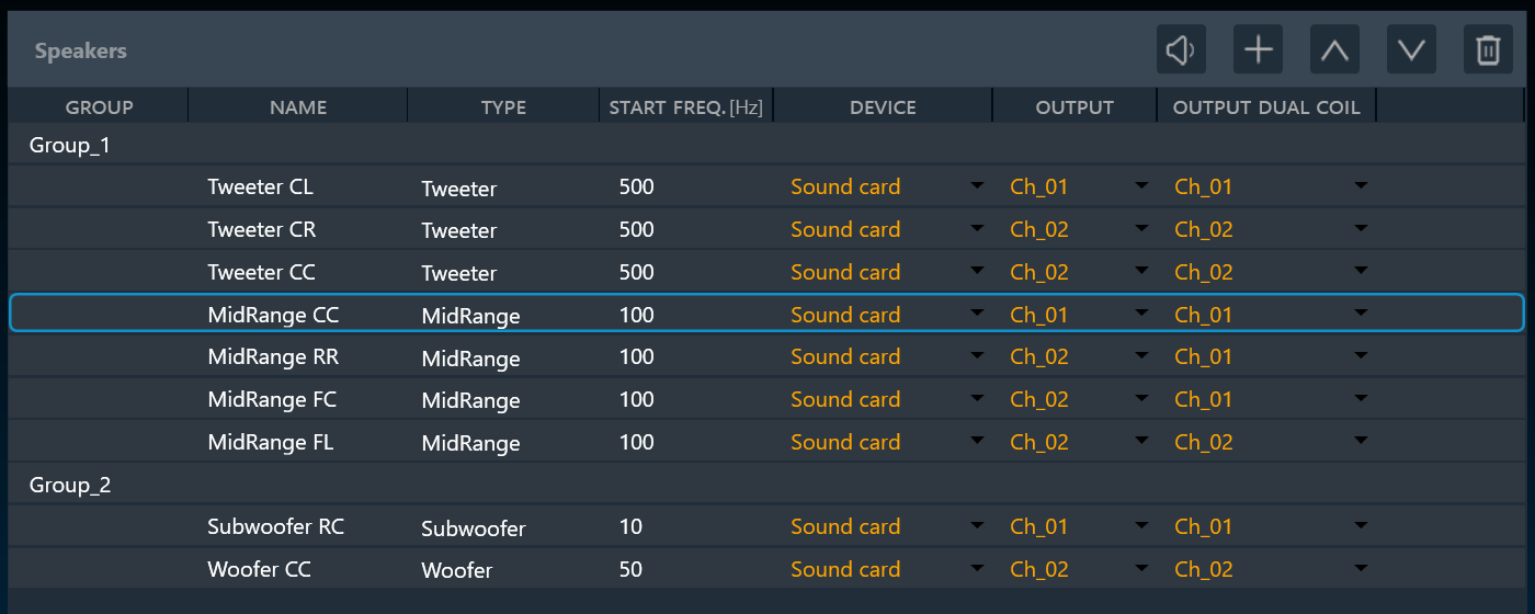
The “device” column of the list allows for the assignment of the following modes to a speaker:
– Master: The stimulus will play through the master output channel (see soundcard configuration)
– Soundcard: Allows for the free choice of a soundcard channel in the “Output” column
– Device: Allows for the assignment of the speaker to a device output channel (see device output mapping) for (un-) muting. The stimulus will play through the master channel.
A mix of the modes is allowed. If any speaker is assigned to the master or device mode, it is not possible to use the soundcard output channel defined as master channel for any speaker in “soundcard” mode. - Managing Speakers List:

- Play Sound: Use this option for quick functionality checks.
- New Group: Click the “+” button above the list to create new groups.
- Move Up: Use the up arrows to move speakers within the list, which can also change their group assignment.
- Move Down: Use the down arrows to move speakers within the list, which can also change their group assignment.
- Delete: If you want to delete any speaker from the list.
Double-click on a speaker or group name in the list to rename it. (Speaker types cannot be changed here.)
Each speaker can have its own “start frequency” set. This high-passes any signal played through that speaker. The “start frequency” can also be adjusted in the generator menu, overriding this setting.
After setting up the speakers in the “Speaker Configuration” window, click on “Microphone Configuration” to set and configure the microphones in the scene.
3.3.Microphone Configuration
On the Microphone Configuration window, you can arrange and configure the microphone.

The available microphone arrays are located to the left side on the Microphone Configuration view .
- Single Microphone
- 4 microphones
- 6 microphones
- 16 microphones
- 4 by 4 array (to measure at 16 different microphone positions using 4 microphones in 4 steps at one array position)
You can perform following actions on Microphone Configuration window:
Positioning Microphone Arrays
- You can freely drag and drop microphone arrays anywhere in the scene.
- Dragging an array far outside the scene will remove it.
Managing Microphone Arrays
- A list of all microphone arrays in the scene is displayed on the right.
- Use the up and down arrows to change the order of the arrays in the list.
- Double-click on an array name and type a new name to rename it.
- Click the delete button to remove an array from the list.

Soundcard Input Assignment:
- Assign any soundcard input channel to each microphone array.
Rotating Microphone Arrays for Sequential Measurements:

- Select “Rotating” for microphone arrays in the list to design a measurement sequence quickly.
- These arrays will automatically snap to each seat, acting as a mobile unit that captures audio at multiple positions.
- The seats will be numbered consecutively, indicating the measurement order.
The number of seats needs to be a multiple of the number of microphones in the rotating array.
- You can keep additional microphones on the scene as fixed positions for more comprehensive data collection. The placement logic for the rotation is as follows:
-
- One mic all seats in order: driver (seat 1), passenger (seat 2), rear behind driver (seat 3), rear behind passenger (seat 4).
- Two mics, two seat car: mic 1 on seat 1, mic 2 on seat 2.
- Two mics, four seat car: mic 1 on seat 1, then on seat 2, mic two on seat 3 then on seat 4.
- Two mics, six seat car: as for 4 seats plus mic 1 on seat 5 (driver side), mic 2 on seat 6.
- Three mics, two seat car: forbidden.
- Three mics, four seat car: forbidden.
- Three mic, six seat car: mic 1 covers first row, mic 2 2nd, mic 3 3rd. First all on the driver, then on the passenger side.
Once all the microphones are configured, click on Mic Settings. This will open Microphone Calibration window. In this window you can adjust all microphones in the array for optimal performance. Additionally, you can load a frequency compensation file into each individual microphone of an element by selecting the individual microphone and clicking “Compensation File”.

3.3.1.Microphone Calibration
Every microphone element (1 or 6 microphone array) must be calibrated separately. The central element of the calibration menu is the list of microphones contained in the current microphone element. The list has the columns:
- Microphone: The number of the microphone within the element.
- Previous value: Offset measured during previous calibration, displayed as comparison.
- Current value: The offset measured during this calibration.
- Compensation File: This is the File provided by mic manufacturer, which will be used for magnitude curve correction.

The type of the microphone element and the currently selected microphone within the element are indicated using an icon (green rectangle).
The soundcard the selected microphone shall be connected to are displayed above the list (yellow rectangle).
The reference sound pressure level of the calibrator can be selected in the upper right (red rectangle).
To calibrate a microphone:
- Choose the microphone you want to calibrate.
- Attach the microphone to the designated channel on the calibration device. Connect the calibrator to the microphone itself.
- Select the appropriate reference sound pressure level (SPL) for your calibration.
- Click the “Calibrate” button. The calibration process should take approximately 2 seconds.
- While calibration is running, observe the level meter (indicated as a black rectangle) for activity on the chosen input channel.
- The calibration will result in an offset value (displayed in red in the “current value” column).
- Choose to accept this value by clicking “Apply” (which will turn the value green) or repeat the calibration process if the value is not satisfactory.
- Clicking “Apply” confirms the calibration value, turns it green, and automatically selects the next microphone that needs calibration (if applicable).
Repeat the procedure for all microphones in the array.
Import: an existing calibration and compensation file path can be imported using “Import” option. This sets the current value for all microphones to the stored offsets. The values must be applied.
Individual microphones can be re-calibrated at any time. Once all calibration offsets are applied, the menu can be closed using “Ok”.
Export: A full set of applied calibrations along with compensation file path can be exported to disk using “Export”.
3.4.Measurement Definition
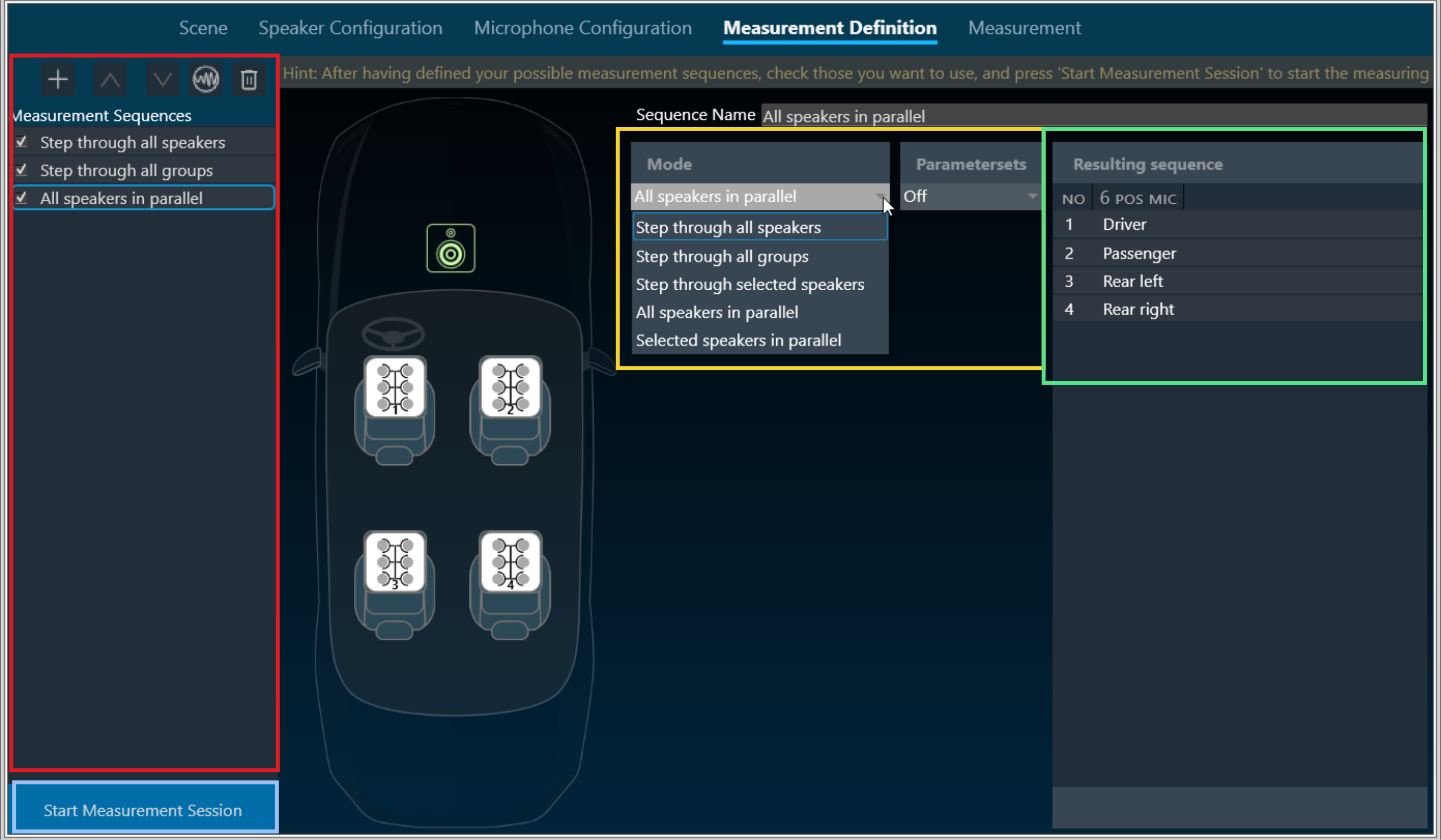
The Measurement Definition screen is the final preparatory screen before the actual measurement. This screen consists of list of Measurement Sequences (highlighted in red), Mode and Parameter configuration (highlighted in yellow), and list of Resulting Sequence measurement (highlighted in green).
Steps to configure Measurement Definition
- On the Measurement Configuration screen, go to Measurement Sequences section and click on the (+) button.
By default, project-specific Generator settings are assigned to each new Measurement Configuration, after which you can configure distinct Generator settings for each Measurement Configuration. - On the Mode selection allows you to change the settings of the specified measurement.
Possible measurement modes are:- Step through all speakers: play back signal through each speaker sequentially
- Step through all groups: play back signal through all groups sequentially, parallel through all speakers in one group
- Step through selected speakers: play back signal through each speaker or group selected in list
- All speakers in parallel: play back signal through all speakers at once
- Selected speakers in parallel: Play back signal in parallel through all speakers/groups selected in list.
The resulting sequence of the currently select measurement is display on the right (green rectangle)
- Once you have configured all the measurements, click on Start Measurement Session to activate the measurement mode.
This opens a new measurement window. - On the Measurement Setting dialog box, enter the session name and click Ok.
If you want to optimize the measurement order select Optimize measuring order and enter the session name. The optimization of the measurement order applies when several sequences with different loudspeakers are defined for at least one rotating microphone.
– If no optimization is applied, the measurement will be performed independently for each sequence, resulting in the rotation of the microphone over all the seats within each sequence.
– When optimization is applied, all the measurements that are linked to a seat position are performed one after the other, regardless of the sequence to which they belong.

For large numbers of sequences, this greatly minimizes the number of microphone repositioning.
Parameters sets configuration is under development.
Even though user can configure different Generator Settings per Measurement Configuration, the Generator Mode will be same for all Measurement Configurations. Only at the project level, Generator Mode can be modified and same will be overwrite to all Measurement Configurations.
3.5.Measurement
The measurement tab consist of following sections.

- Measurement Configurations: This section displays the measurement sequence list of all the measurements included in this session. The measurement number indicates the order in which the measurements will be performed.
- Speaker and Microphone layout: This section shows the layout of the speakers and microphones on the selected car.
- Instructions: This section contains microphone calibration warnings and suggestions to relocate microphones.
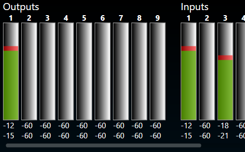
- Inputs/ Outputs: This section shows the current input and output levels using the meters.
- Measurement Inspection viewer: This section displays the result of each measurement.

You can highlight a channel by selecting the channel from the ‘Highlight input channel’ drop down menu.
The Measurement Viewer loads with default settings. You can change the viewer settings using the Settings icon.
Viewer Settings Properties
The Viewer Settings window contains the following options, which are saved on an application-wide basis:

| Properties | Description |
| Frequency Domain |
Smoothing: Smoothing is a technique that reduces variations in plotted curves to improve the visual perception of trends or patterns in frequency response or level measurements. It is commonly used in audio analysis and equalization tasks to enhance clarity while considering the trade-off between noise reduction and preservation of important details. By default, the frequency smoothing function is set to Off. and Frequency smoothing has following selections [1/48, 1/24, 1/12, 1/6, 1/3, 1] referring of sample points used per octave. |
|
FFT Window: The default setting for the FFT window is ‘With time domain setting’ ; sets the same signal length displayed for the time signals as base for the FF. Full signal option; takes the entire time signal as base for the FFT. |
|
| Time Domain |
IR Mode: Set the length of the time signal displayed in IR mode. By default, the IR mode is set to 5s. When Generator Mode is selected as recording, IR mode will be disabled. |
|
Recording Mode: Set the length of the time signal displayed in Recording mode. By default, the IR mode is set to 5s. |
Performing Measurement
Prerequisites
- Ensure that the required car is set in the Scene tab, for more details refer to Scene.
- Ensure that the speaker setup is configured in the Speaker Configuration tab, for more details refer to Speaker Configuration.
- Ensure that the microphone setup is configured in the Microphone Configuration tab, for more details refer to Microphone Configuration.
- Ensure that you define all measurements, set the mode and parameters, and check the measurement sequence in the Measurement Definition tab, for more details refer to Measurement Definition.
Steps to perform Measurement Session
- Once all the measurement configurations done described in the prerequisites, click on the Start Measurement Session. This will activate the measurement mode.
- On the Measurement Setting dialog box, enter the session name and click Ok.
If you want to optimize the measurement order select Optimize measuring order. The optimization of the measurement order applies when several sequences with different loudspeakers are defined for at least one rotating microphone.
– If no optimization is applied, the measurement will be performed independently for each sequence, resulting in the rotation of the microphone over all the seats within each sequence.
– When optimization is applied, all the measurements that are linked to a seat position are performed one after the other, regardless of the sequence to which they belong.
For large numbers of sequences, this greatly minimizes the number of microphone repositioning. - The measurement module acquisition window will now open as a pop-up window, allowing access to tuning panels in the signal flow without obstruction. This enables manual muting and unmuting of necessary speakers through panels during measurement acquisition, especially in cases where automatic measurement isn’t feasible.
- Once the window open, following operation will happen.
-
- On the measurement configuration section, the measurement will start sequentially. All successfully completed measurements are displayed in green, aborted measurements displayed in red.

In the example below, two “Step through selected loudspeakers” sequences are about to be performed. Due to measurement optimization, the two driver seat measurements will be performed immediately after each other, as indicated by measurement numbers 1 and 2.

- On the instructions section, a warning is displayed regarding microphone calibration and microphone relocation. To proceed, select the appropriate checkbox, once all instructions are confirmed, click Measure to start measurement.
If you want to stop after each measurement, then select Manual Measurement (Pause after each step) option.

This stopped time can be used to further inspect the result in the viewer in the time (max is 5s for IR and max 10s for recording) or frequency domain as impulse response (IR) or pure recording.
During a pause, you can trigger a repetition of the last measurement or skip the next measurement from the sequence list.
– To repeat the last measurement, click Previous.
– To skip the next measurement, click Skip.
Repeating a measurement automatically disables the automatic measurement mode. It can be re-enabled any time.

A pause is automatically activated when the measurement requires user action, e.g., the placement of a microphone on another seat.
- On the measurement configuration section, the measurement will start sequentially. All successfully completed measurements are displayed in green, aborted measurements displayed in red.
-
- On the Inputs/ Outputs section, the current input and output levels are shown using the meters.
Once the actual acquisition is complete and the measurement is only being post-processed, the message “Capture complete! ” appears in the instructions box.
The result of each measurement is displayed in the Measurement Inspection viewer section. - On the Measurement Inspection viewer, display result of each measurement.

- On the Inputs/ Outputs section, the current input and output levels are shown using the meters.
4. Once all steps of the measurement procedure are completed, click Finalize to store the measurement.
You can rename the session at any point during the measurement. Click Cancel to discard the measurement
Generally, you can exit the Measurement window only when a session is cancelled or finalized.
The following actions are restricted during a measurement session:
- Opening Sound card configuration in IR measurement
- Opening Device Output Mapping in IR measurement
- Opening Generator Settings in IR measurement
- Opening Reset all in IR measurement
- Opening Import in IR measurement
- Opening Test Sound in IR measurement
- “Start Measurement Session” button is disabled
- Application Exit
- New Project Import
- New Project Create
- Delete Project
- Open Project
- Save and Go Back in SFD
- Save in Device View
If you try to perform any one of the above actions, a message will be shown “Measurement session in progress”.
