Memory latency levels refers to the access speed of the memory segments. The access speed of the memory where the data is placed, significantly affects MIPS consumption of an algorithm. Thus in a given SFD, placing the data buffers (memory records) in the memory segments in an optimal way is crucial for overall MIPS consumption.
The latency level of each memory record can be set in two ways –
- By the developer during coding based on the perceived complexity of the object
- By the Signal Flow Designer during design phase based on the existing objects in the design and the available resources on the platform.
By default the latency levels of all the memory records of all the objects are set to the highest level (16) during instantiation. The developer can set the recommended latency level in the method – getMemRecords(). If the latency level for a specific memory record is not set in this method, the default level set during instantiation will remain. The latency level and other memory details (size and alignment) are passed to the GTT in response the function call – getTuningInformationBufferXML().
With the details of all the memory records of all the objects through the method – getTuningInformationBufferXML() – GTT presents the information through the below GUI to the Signal Flow Designer.
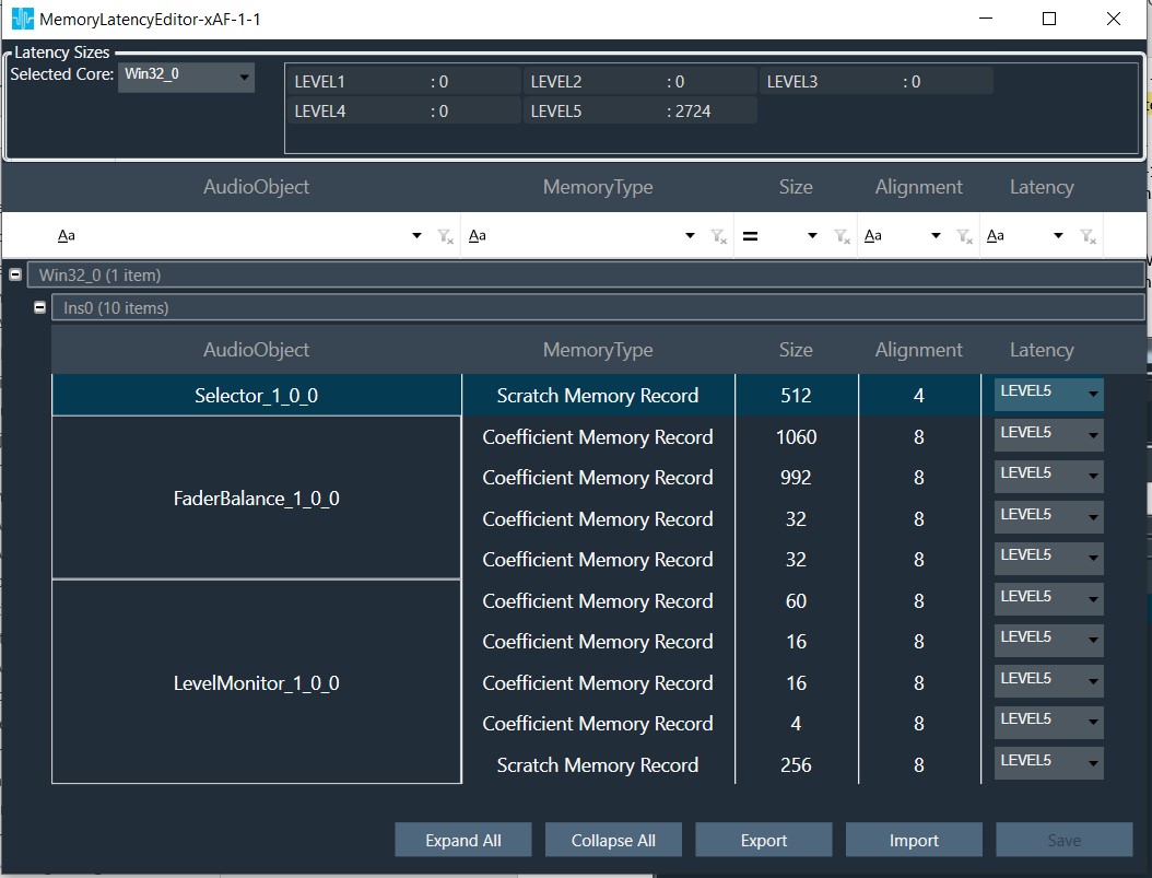
The Signal Flow Designer shall change the latency level (with the drop-down menu) for optimal performance based on the available resources and importance of this particular memory record among the other memory records of the other objects present within the signal flow. The total memory requirement for the signal flow in each memory level is displayed at the top. The desired memory latency table can also be exported to a file / imported from a file.
These memory details are passed to the device as part of SFD.
On boot-up the framework shall parse the SFD data with the DSFD Parser and allocate memory for each object at the configured latency level in the method – initFramework().