
1.Granular Synthesis Compound AO
Granular synthesis is a basic sound synthesis method that operates on the microsound time scale. These small pieces around 1 to 50 ms are called Grains. Multiple grains may be layered on top of each other, and may play at different pitch, phases, volume, among other parameters.
On the microsound time scale, sound can edit and process into small grains, and grains can be laid in different ways. This technique unlocks the potential of short WAV files to deliver a rich and immersive audio experience.
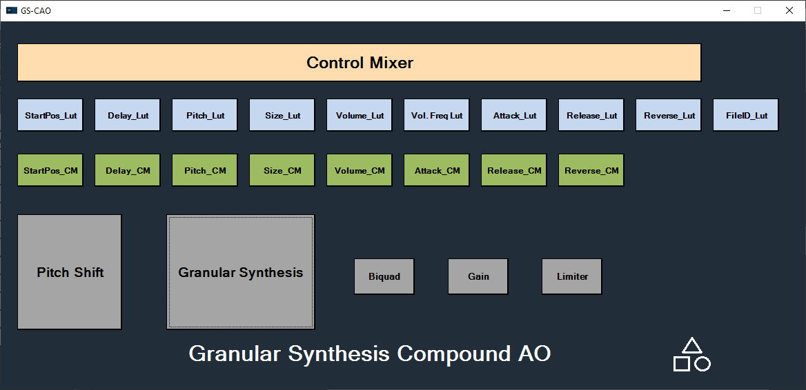
Granular Synthesis Compound audio object is composition of eight audio objects.
- Granular Synthesis: Granular Synthesis enables and disables Pitch Shift channels, which allow you to access different offsets in a WAV file and send pitch and offset values to different channels. Then, receive the audio signal from Pitch Shift and apply the generated window table to it. Granular Synthesis also combines all grains and output.
- Control Mixer:
- LUTs: The LUT audio object generates outputs for Granular Synthesis parameter value according to engine real-time signals.
- Control Modulators: The Control Modulator generates randomness for Granular Synthesis parameters according to the tuned functions and amplifies the randomness according to engine real-time signal.
- Pitch Shift: The Pitch Shift read the WAV file stored in flash and generate a pitch-shifted audio signal.
- Biquad:
- Gain: Gain audio object applies master gain on the output of Granular Synthesis.
- Limiter: The Limiter limits Granular Synthesis output when the summed output of grains is too high.
The Granular Synthesis panel allows real-time updates to a Look-Up Table (LUT) used for audio tuning. If you keep the Granular Synthesis panel open while tuning any LUT with value (column 1) and modulation (column 2) columns connected to the Granular Synthesis audio object, then whenever the value (column 1) changes, the modulation (column 2) will be updated if the row in the Granular Synthesis panel corresponds to the selected grain.
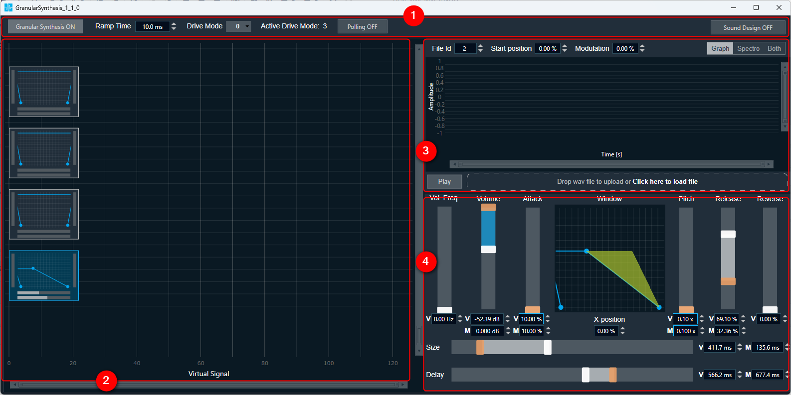
2.Granular Synthesis panel
The Granular Synthesis Panel is to tune Granular Synthesis Audio Object as well as other audio objects in Granular synthesis CAO.
The Panel is created to use with Granular Synthesis CAO, not to use alone with Granular Synthesis Audio Object.
The Granular Synthesis can be launched from a custom panel using System Function. For more details about launching custom panel in GTT, refer Create a Custom Panel in GTT
The Granular Synthesis panel contains following sections:
- Top panel
- Grains chart
- Waveform
- Grain Editor
Value ranges are displayed inside a tooltip for grain editors, fileID editor, Start position, Modulation and Ramp time editor.
Multiple Drive Modes
Granular Synthesis panel supports multiple drive modes from V+1 Release onwards.
You can select the required drive mode in panel and update tuning for the specific drive mode. On changing drive mode in panel, all parameters in panel will get mapped to respective linked LUT tab. The current active drive mode in device can be monitored in this panel.
If depth of linked LUTs in Granular Synthesis CAO is 1 or audio object mode of linked LUTs is 2D, then only one drive mode is present in Granular Synthesis panel and no option to switch drive mode.
Depth of all linked LUTs should be identical to function this panel properly.
2.1.Top Panel
In Granular Synthesis panel the top panel section contains following features:
- Granular Synthesis button: To On or Off Granular Synthesis option.
- Ramp Time: To modify Ramp Time value (range displayed inside a tooltip when hovering the mouse over the value)
- Drive Mode: To select the drive mode in the panel
- Active Drive Mode: Displays the current drive mode in device
- Polling toggle button: To fetch active drive mode in every one second.
- Sound Design button: To On or Off sound design option. When sound design is On, the changes making in parameters will not reflect immediately in respective LUTs. On changing sound design to Off after making parameter changes, a prompt will appear to apply parameter changes to LUTs. If you click yes, the values will reflect immediately in LUTs, otherwise not. When sound design is Off, all the changes making in parameters will immediately reflect in LUTs.
![]()
In Sound Design Mode LUTs and Control Modulators are updated, while in normal mode just LUTs.
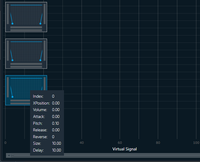
2.2.Grains chart
The Virtual Control Signal value is represented on Grain Chart as x-axis position.
The Grain Markers provide visual information about each grain. They display the Pitch value, Reverse value, Size value, and Delay value. Additionally, a chart display Volume, Attack and Release values.
No two grains can share the same virtual control signal value.
If more than 5 rows are used, you can use a scrollbar to see additional rows. Modifying the values in Grain Editor are reflected on the selected Grain Marker.
Changing Grains and Parameters
- You can choose a grain and adjust its settings in both the Grain editor and Wave editor. These adjustments will directly affect the Look-Up Table (LUT) values.
- When you switch to a different grain, the Grain and Wave editors will automatically update to display the parameter values specific to that chosen grain.
On grains chart you can perform following actions:
- Add grain
- Duplicate grain
- Remove grain
Add grain: A new grain will have a virtual signal value that corresponds to where the context menu was opened along the x-axis.
- If a new grain is added between two existing ones (from the x-axis), the parameter values will be interpolated linearly.
- If a new grain is added before the first grain, the parameters from the subsequent grain will be used.
- If a new grain is added after the last grain, the parameters from the previous grain will be used.
Interpolation excludes FIleID.
Duplicate: Copying selected grain while retaining original grain parameter values, and setting the virtual control signal value to the location where the context menu was opened along the x-axis.
Remove grain: Removing selected grain (via the context menu or by pressing the Delete key on the keyboard).
It is possible to change the virtual control signal value of the grain by dragging the Grain Marker. Dragging a grain with the Shift key pressed applies the same interpolation rules used when adding new grains.
Use the mouse wheel to adjust the zoom level on the X-axis.
2.3.Wave editor
The Wave editor is used for visualizing wave signal. It used for grain-based synthesis and tuning start position value in a visual manner.
You can change the display view between waveform or spectrogram or we can display both simultaneously.
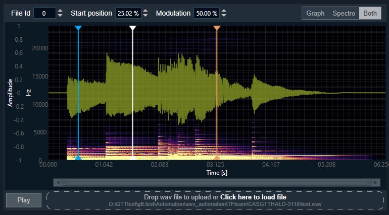
To load the audio file, use the drag and drop method or by selecting them from a directory.
File loaded into the panel is mapped to the FileID grain parameter by its file path. The FileID is considered a tunable parameter and loaded file is for visualization purposes only.
When switching between systems, make sure to use the appropriate files.
Supported Audio Format: Only WAV audio files type is supported. Once you’ve loaded your WAV file, use the Play button in the bottom left corner of the editing window to play the audio.
Using wave editor you can perform following modifications.
- You can modify the Start position and modulation value by entering the values in the text box.
- Alternatively, you can drag the vertical marker on the chart for a more visual adjustment, all the changes will be replicated in Start position and modulation value.
- You can Modify FileID using textbox.
The wave editor allows you to zooming in both axes. To zoom in and out, you can scroll using mouse.
2.4.Grain editor
The Grain editor view allows modification via slider and textbox of following parameters:
- Volume frequency value
- Volume base and modulation value
- Attack base and modulation value
- Pitch base and modulation value
- Release base and modulation value
- Reverse value
- Size base and modulation value
- Delay base and modulation value
- X-position
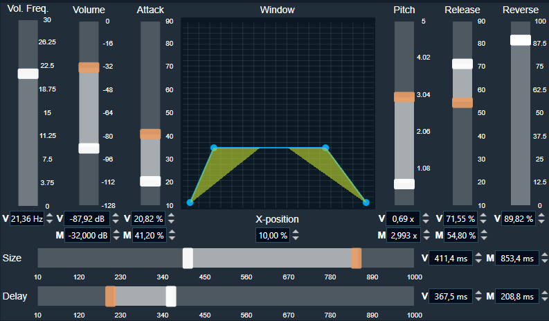
Value ranges are displayed inside a tooltip when hover the mouse over the textbox. When the X-position is changed (ex. by Enter), you can use the Shift key to handle interpolated values.
A chart displaying graphical representation for following parameters:
- Attack base and modulation value
- Release base and modulation value
- Volume base value
Modifying values in Grain Editor are reflected on the selected Grain Marker.