When clicking on the Analyzer settings button in the ribbon bar the analyzer window opens:
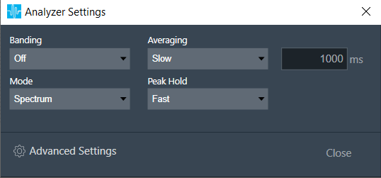
With “Mode” the analyzer mode can be selected.
Following modes are available:
- Time: Displays source channels in the time domain (one block of 4096 samples)
- Spectrum: Displays the spectrum of the source channels
- Multiplexer: Switches the RTA into an multiplexer mode where multiple source channels are combined to two average channels
- Delay : Displays source channels in the time domain. The delay measurement is done by cross correlation between a reference channel and a channel which contains the reference signal which went through a certain path (e.g. amp – speaker – microphone). From the position of the maximum within the correlation result the delay can be calculated. Calculated Delay value is displayed in Channel viewer in Delay column.
- Phase : Displays the magnitude and phase of the source channels. Phase can be wrapped and unwrapped using Graph Settings in settings window. The phase measurement is done by a dual channel FFT analysis.
- THD : Displays the magnitude and THD of the source channels. This is an Impulse response measurement with exponential sine sweep. When this analyzer mode is selected ‘ExpSweep’ Generator mode is set and user not allowed to change to other modes. ‘Play’ button is disabled in Generator view and with ‘Single’ button he can generate ‘ExpSweep’ once .
The “Banding” can be adjusted in Spectrum or Multiplexer mode. With banding Off all calculated frequency bins of the spectrum are displayed. In this setting a very detailed analysis is possible. The only drawback is that the higher the FFT size, the more data have to be calculated and displayed, and hence more CPU power is being used. When banding is switched on, frequency bins are combined to groups. The width of such a group can be set by fractions of an octave, e.g. Oct12 i.e, one band has the width of a 12th of one octave.
Depending on the test signal, smoothing of the spectrum over time is required.
This can be set by the “Multiplexer” mode:
- Fast: Small smoothing time constant and hence only a small amount of smoothing (time constant 125 ms)
- Slow: Large smoothing time constant and hence significant smoothing (time constant 1000 ms)
- Custom: Custom smoothing time constant and a textbox with ms which takes input
Detailed settings can be done with the “Analyzer Settings” Dialog:
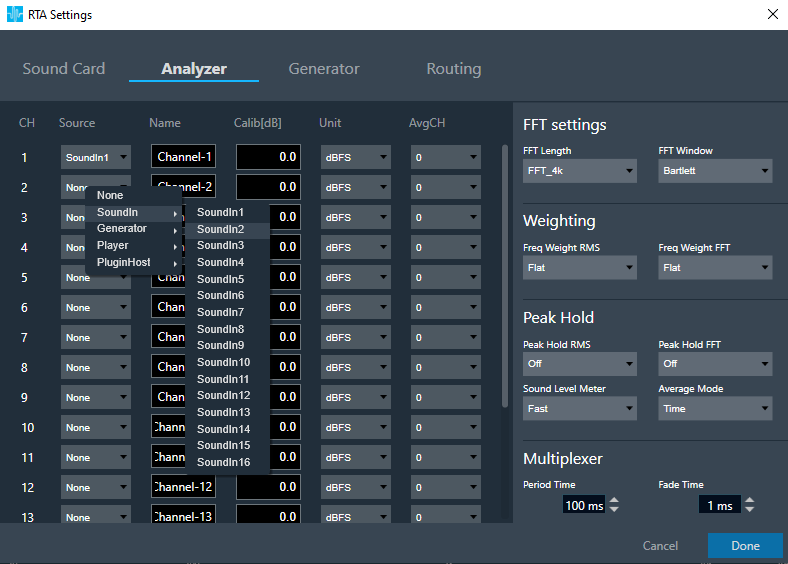
With the channels list, following adjustments can be made:
- Source: This defines the input of a certain analyzer channel. By clicking on the control (default: “None” for no input), a context menu pops up from which the desired source can be chosen.
- Name: here the name of an analyzer channel can be set. This name appears in the channel viewer and will be set as a default name when storing measurements as traces.
- Calib: when a channel is being calibrated for a certain microphone the determined value appears here. It can also be overwritten by entering a desired value. The unit is „dB“; the analyzer input stream will be scaled by this value.
- Unit: here the unit of the analyzer source can be set. This unit appears later in the channel viewer.
- AvgCH: when the analyzer is in „Multiplexer“ mode this control determines to which „Average“ channel the analyzer source is added. With „0“ the channel is omitted, „1“ or „2“ will add the channel to „Average-1“ or respectively „Average-2“.
- Channels 17 and 18 are reserved for the „Average“ channels. Here only the name can be edited.
- Delay : Add/subtract time delay in milliseconds. In Phase measurement we can add/subtract time delay to compensate HW and/or acoustic delay.
FFT Settings
The length of the FFT which is used for the spectrum calculation can be set between starting from 4096 up to 131072 samples (4k..128k). The higher the value, the finer the frequency resolution of the spectrum. But with increasing lengths the CPU load will increase due to the higher amount of calculations and data to plot.
By choosing a FFT window the user can define the way how a finite data set, determined by the FFT length is cut out of the more or less infinite input data stream.
See https://en.wikipedia.org/wiki/Window_function for more details on windowing.
Default value of FFT window will be “Hann”
Weighting
Here the user can choose how the input signal is weighted in the frequency range. This can be done independently for the time domain (Freq Weight RMS), and the frequency domain (Freq Weight FFT) measurements.
See https://en.wikipedia.org/wiki/A-weighting for more details on weighting.
Peak Hold
Here the user can adjust the peak hold feature independently for the time domain (Peak Hold RMS) and the frequency domain (Peak Hold FFT) measurements.
- Off : Disables the peak hold feature
- Fast: Sets the hold time to 1 sec
- Slow: Sets the hold time to 5 sec
- Forever: Holds the peak values until the Reset button in the ribbon bar is clicked
Clipping
Clipping occures when the input signal exceeds the full scale range of the input sound device. RTA can detect this condition and signal it. There is also an option to exclude the data packet which contains clipped data from the analysis. Modes:
- Off: Disables clipping detection
- On: Enables clipping detection
- ExcludeData: Enables clipping detection and excludes clipped data packets from being analyzed
When data are clipped and the detection is enabled a “DATA CLIPPED” message on the top right corner of the graph is shown.
Other Settings
The time constant for the RMS calculation can be selected under „Sound Level Meter“. It is similar to the Averaging control in the Analyzer window:
- Off: No smoothing
- Fast: Small smoothing time constant and hence only a small amount of smoothing
- Slow: Large smoothing time constant and hence significant smoothing
- Forever: Extreme smoothing time constant
The analyzer mode “Multiplexer”, where multiple channels are added to a single “Average” channel can be set to “Time” and “Freq”. In “Time” mode the analyzer works as a multiplexer. It combines multiple input audio signals into one audio signal by dividing the input channels into equal fixed-length time slots and mix them into a common output channel with fading between channels. The length of the time slots and the fading characteristic can be configured during runtime. The output signal is the signal of one input channel at a time. If the last input channel is reached, the next input channel will be the first input channel again. Since in this mode only on or two spectrums are calculated it can be used when CPU load is an issue.
In “Frequency” mode the analyzer calculates the spectrum of each individual channel and calculates the average of all spectrums. This method is faster and more precise because there are no artefacts from switching between channels as it would occur in the “Time” mode.
Multiplexer
When the multiplexer mode is set to “Time” the multiplexer gets active. Here the user can set the length of a time slice (“Period Time”). “Fade Time” sets the time within one channel is faded into the next one.