1.Introduction
The VSS places mono sound sources with variable distance and angle in a 360° environment. The technology is scalable in terms of number of input sources (virtual sound sources), number of speakers and positions of speakers.
There are two configurations of VSS.
- VSS 1.0
- VSS 1.5
1.1.VSS 1.0 CAO
The reference compound audio object (CAO) of VSS 1.0 is configured for four independent input sources and five output speakers
- Front Left (‑30°)
- Front Right (+30°)
- Center (0)°
- Rear Left (‑155°)
- Rear Right (+155°)

1.2.VSS 1.5 CAO
The reference compound audio object of VSS 1.5 is configured for four independent input sources and seven output speakers.
- Front Left
- Front Right
- Center
- Height Left
- Height Right
- Headrest Left
- Headrest Right
The Height speakers support the playback from directions of +-90°. The Headrest speakers are used for playback of the virtual Rear speakers. The Fronts, Heights, and virtual Rears are used for playback of the directional cues and in addition to virtual Rear playback, the Headrest is also used for non-directional main playback.

2.VSS Signal Flow
2.1.VSS 1.0 CAO - Signal Flow
The CAO of VSS has the following inputs and outputs:
Audio input
- Mono sound source #1
- Mono sound source #2
- Mono sound source #3
- Mono sound source #4
Audio output
- Speaker channel Front Left
- Speaker channel Front Right
- Speaker channel Center
- Speaker channel Rear Left
- Speaker channel Rear Right
Control input
- Control signal Angle Source #1
- Control signal Distance Source #1
- Control signal Angle Source #2
- Control signal Distance Source #2
- Control signal Angle Source #3
- Control signal Distance Source #3
- Control signal Angle Source #4
- Control signal Distance Source #4
Control output
The CAO is not having any control outputs.
SFD of VSS 1.0
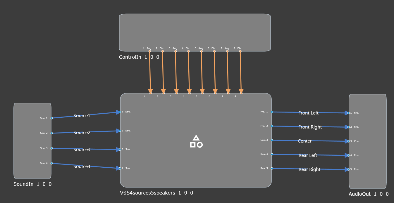
The following Figure shows the internal signal flow of VSS 1.0.

2.2.VSS 1.5 CAO - Signal Flow
The CAO of VSS 1.5 has the following inputs and outputs (Figure 3):
Audio input
- Mono sound source #1
- Mono sound source #2
- Mono sound source #3
- Mono sound source #4
Audio output
- Speaker channel Front Left
- Speaker channel Front Right
- Speaker channel Center
- Speaker channel Headrest Left
- Speaker channel Headrest Right
- Speaker channel Height Left
- Speaker channel Height Right
Control input
- Control signal Angle Source #1
- Control signal Distance Source #1
- Control signal Angle Source #2
- Control signal Distance Source #2
- Control signal Angle Source #3
- Control signal Distance Source #3
- Control signal Angle Source #4
- Control signal Distance Source #4

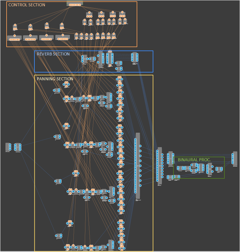
The following Figure shows the internal signal flow of VSS 1.5.
3.1.VSS 1.0 CAO - Panel
The main GTT tuning panel of VSS 1.0 is divided into Source Sections, Mixer Section and Reverb Section as follows.

Source Section
Each mono input source has an individual tuning section on the main panel.

Each source section includes:
| Parmeter Name | Description |
| Angle and Distance | Two controls knobs for the two control signals angle and distance are for manually placing the sound source during a tuning session. |
| Input EQ | It opens the biquad panels for the input EQ |
| Distance EQ | It opens the biquad panels for the distance EQ |
| Amplitude Panning | It opens the look-up table (LUT) panels for the angle-dependent speaker amplitude values. |
| Panning Correction | It opens the LUT panel for angle-dependent overall amplitude correction. |
| Distance EQ LUT | It opens the LUT panel for adjusting the minimum and maximum cutoff frequency for the Distance EQ, i.e. a distance-dependent low-pass filter. |
| Distance to Gain | It opens the LUT panel for distance-dependent dry and wet gains of the input source. |
| Input Gain | It adjusts op mutes the input gain of the source. |
Mixer Section
The Mixer Section of the main panel includes a button Output Matrix that opens the matrix mixer panel as well as a section for controlling the output levels of each speaker channel individually.

Reverb Section
The Reverb Section of the main panel includes a button to open the settings panel of the reverberation algorithm (VenueVerb), a button for opening the reverb input matrix, a preset section for calling pre-generated venue presets, as well as a knob for controlling the reverb master level.

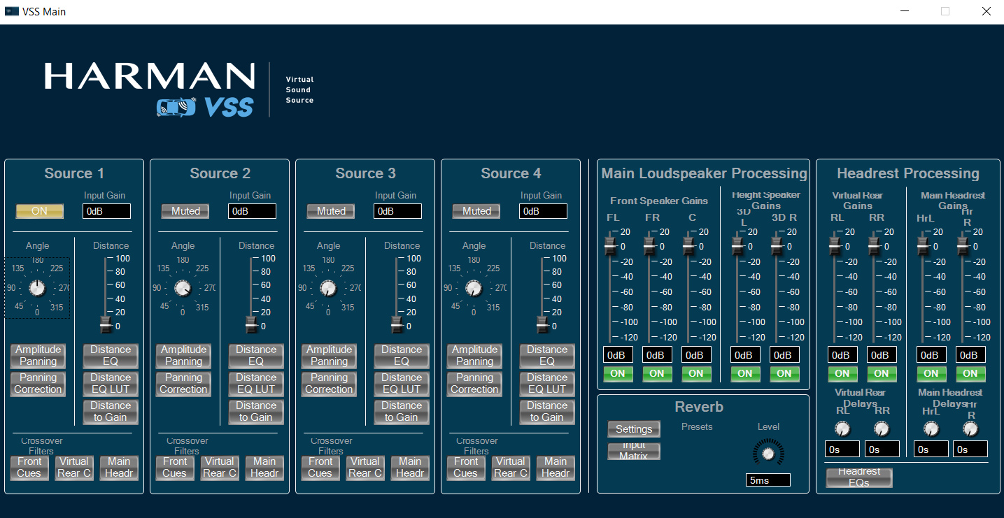
3.2.VSS 1.5 CAO - Panel
The main GTT tuning panel of VSS 1.5 is shown in the following Figure. It is divided into Source Sections, Main Loudspeaker Processing Section, Headrest Processing Section and Reverb Section as follows. For details please see VSS documentation.

Source Section
Each mono input source has an individual tuning section on the main panel.

Each source section includes:
|
Parmeter Name
|
Description
|
|
Angle and Distance
|
There is one control knob for the Angle control signal and one control slider for the Distance control signal, which are used for manually placing the sound source during a tuning session. |
|
Input EQ
|
It opens the biquad panels for the input EQ
|
|
Distance EQ
|
It opens the biquad panels for the distance EQ
|
|
Amplitude Panning
|
It opens the look-up table (LUT) panels for the angle-dependent speaker amplitude values.
|
|
Panning Correction
|
It opens the LUT panel for angle-dependent overall amplitude correction.
|
|
Distance EQ LUT
|
It opens the LUT panel for adjusting the minimum and maximum cutoff frequency for the Distance EQ, i.e. a distance-dependent low-pass filter.
|
|
Distance to Gain
|
It opens the LUT panel for distance-dependent dry and wet gains of the input source.
|
|
Input Gain
|
This section allows to adjust the input gain of the source using the text input field and to mute the source using the On/Muted button.
|
|
Distance EQ
|
It opens the biquad panels for the input EQ and distance EQ, respectively.
|
The Crossover Filters section allows to access the panels for cue/main processing crossover filters tuning. It includes the following buttons:
|
Parmeter Name
|
Description
|
|
Front Cues
|
It opens the biquad panels for the front channel cue high pass filters (i.e. front left, front center, front right, height side left, height side right) |
|
Virtual Rear Cues
|
It opens the biquad panels for virtual rear channel cue high pass filters |
|
Main Headrest
|
It opens the biquad panel for the main headrest playback channel low pass filters |
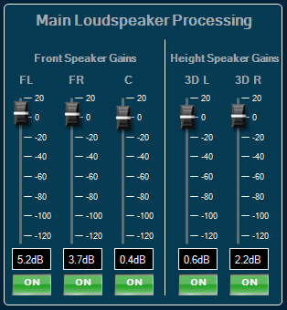
Main Loudspeaker Processing Section
The main loudspeaker processing section allows to adjust the gains of the high frequency cue signals, which are played back on the main loudspeakers (front left, front center, front right, height side left, height side right).
|
Parmeter Name
|
Description
|
|
Front Speaker Gains
|
The Front Speaker Gains sections allows to adjust the gains of the front left (FL), front right (FR) and front center (C) speakers. |
|
Height Speaker Gains
|
The Height Speaker Gains section allows to adjust the gains of the support height speakers, height side left (3D L) and height side right (3D R). For each channel there is a gain slider, a gain text field and a mute button. |
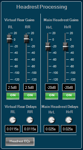
Headrest Processing Section
The headrest processing section allows to adjust the gains of the channels, which are played back through the headrest loudspeakers.
|
Parmeter Name
|
Description
|
|
Virtual Rear Gains
|
The Virtual Rear Gains section allows to adjust the gains of the virtual rear left (RL) and the virtual rear right (RR) channels. The virtual rears play on when the corresponding angle control is directing to an angle of a rear speaker direction. |
|
Virtual Rear Delays
|
The Virtual Rear Delays section allows to adjust the delays of the virtual rear channels. There is a rotary knob and a text entry field for each of the virtual channels. |
|
Main Headrest Gains
|
The Main Headrest Gains section allows to adjust the gains of the main playback, which is played back over the headrest speakers. |
|
Main Headrest Delays
|
The Main Headrest Delays section allows to adjust the delay of the main playback channels, to allow tuning of the delay alignment between the cue playback channels and the main playback channels. |
|
Headrest EQs
|
The Headrest EQs button opens the biquad panel for the headrest EQ, which is a two channel filter object that applies equalizing filters to the mix of the virtual rear and the main headrest signals of the left and right channels. |
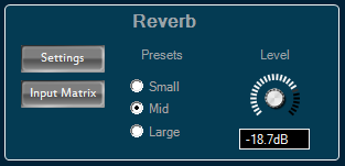
Reverb Section
The Reverb Section includes a button to open the settings panel of the reverberation algorithm (VenueVerb), a button for opening the reverb input matrix, a preset section for calling pre-generated venue presets, as well as a knob for controlling the reverb master level.
4.VSS CAO Integration
4.1.Preset files
VSS CAO has three preset files. These preset files have difference in reverb settings along with room size difference.
|
Preset File Name
|
Description
|
|
Small
|
Length of the longest wall of room aka overall dimension of space is 9.77 meters. |
|
Mid
|
Length of the longest wall of room aka overall dimension of space is 10.1278 meters. |
|
Large
|
Length of the longest wall of room aka overall dimension of space is 11.01 meters. |
4.2.VSS CAO 1.5 - .cao format and panel linking
From S+2 release, CAOs are released in .cao file format. Below are the instructions for panel linking for the external control inputs to the CAO:
- Import the CAO and add it to the SFD. Double click on the CAO in the SFD pane to open the panel. Some of the panel elements may have a warning symbol near them (shown below), indicating that the parameters are not correctly linked to the external control inputs.

- As an example, to link the angle control input pin for source 1, go to the panel designer and navigate to Venue -> Room 1 -> 0x01 : virtual venues-1 -> MasterClass -> Master Pin. Now, drag and drop Angle1 on to the Angle element of Source 1 to link the control input. Once the linking is done correctly, the warning symbol will disappear. Do the same for the other elements as well.
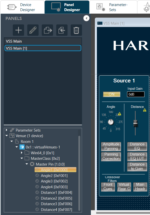
- Once all the control inputs pins are correctly linked, the warning symbols on the panel elements should no longer appear.