Table of Content


4.Create a Signal Flow
Before creating a signal flow, it is necessary to complete the following configurations.
- Make sure you need to add a device to the project. For more information on how to create a project and add device to the project, refer Create a New Project.
- Once you have created the signal flow, the next steps involves tuning and analyzing the signal flow. To analyze the signal flow according to your specific requirements, you need to configure the analyzer settings. The analysis can be performed using the IVP RTA window. For more details on IVP RTA settings, refer Real Time Analyzer User Guide.
If you are running a virtual device select WIN32(legacy) or WIN64 (IVP and VST3).
Not matching core types will cause issues on your device (virtual and real).
Follow the below steps to create a signal flow design:
- On the Device View, drag and drop the Xaf Instance from the toolbox to the virtual core

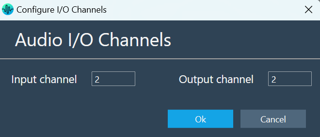
This action opens the Configure I/O Channels message box. - Enter the Input channel and Output channel value and click OK. The audio objects inside the signal flow designer are filtered based on Data Format of the core.
- Select the Xaf Instance and configure the core object properties; Sample Rate and Block Length.
- Sample Rate: This sample rate will be applied to all the audio blocks in the signal flow
- Block Length: It is required internally by the xAF framework.
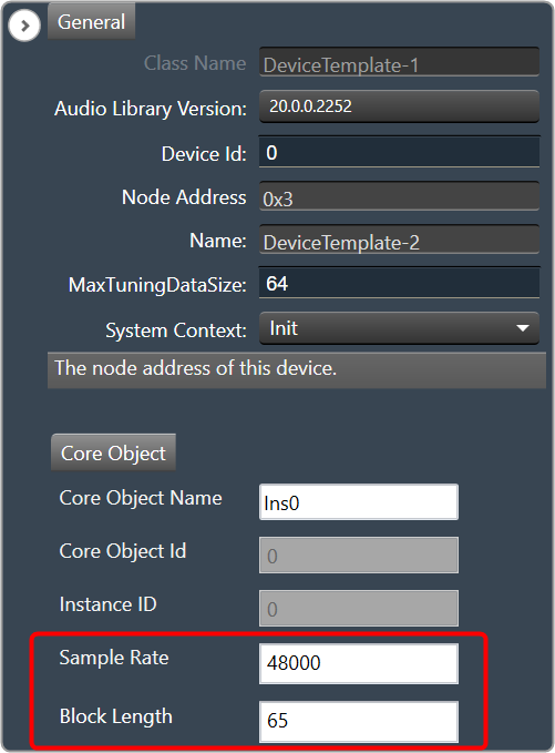
- Once you configured the Xaf Instance core object properties, click Save.
- Double-click on the Xaf Instance to open the Signal Flow Designer window.
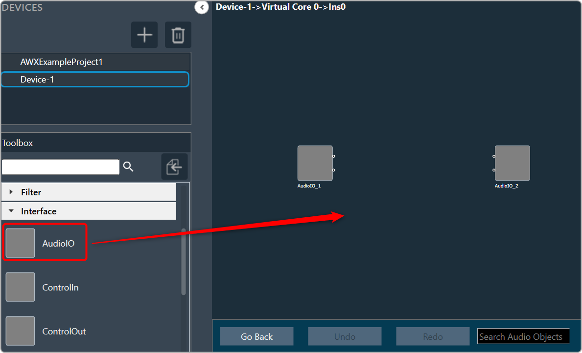
- On the Signal Flow Designer, go to the Toolbox section, expand Interface, and drag AudioIO audio object to the design canvas. Similarly add another AudioIO audio object to the design canvas.
When adding an xAF instance to a device that is already online, this AudioIO can be added. Thus, this step is only necessary if these two AudioIO objects are absent.
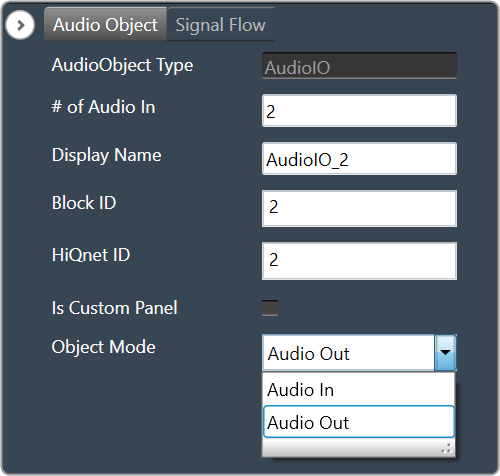
- Select one of the AudioIO audio object and set the Object Mode parameter to Audio In. Similarly, select another AudioIO audio object and set the Object Mode parameter to Audio Out.
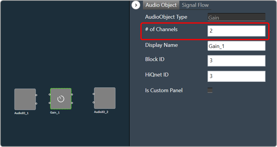
- Expand Basic and drag Gain audio object to the Signal Flow view. You can use any of the audio object, for example Gain audio object is used.
- Select the Gain audio object and set # of channels parameter to 2.
The number of channels determines the number of connectors that will be assigned to the AO. In GTT, you can allocate as many channels as required for your device.
- Press CTL+A or hold the CTRL key, to select an individual audio object from the Signal Flow view, and click Connect Blocks to connect all the audio object.
Or
You can connect the pin manually by establishing a connection between each pin of the AO.
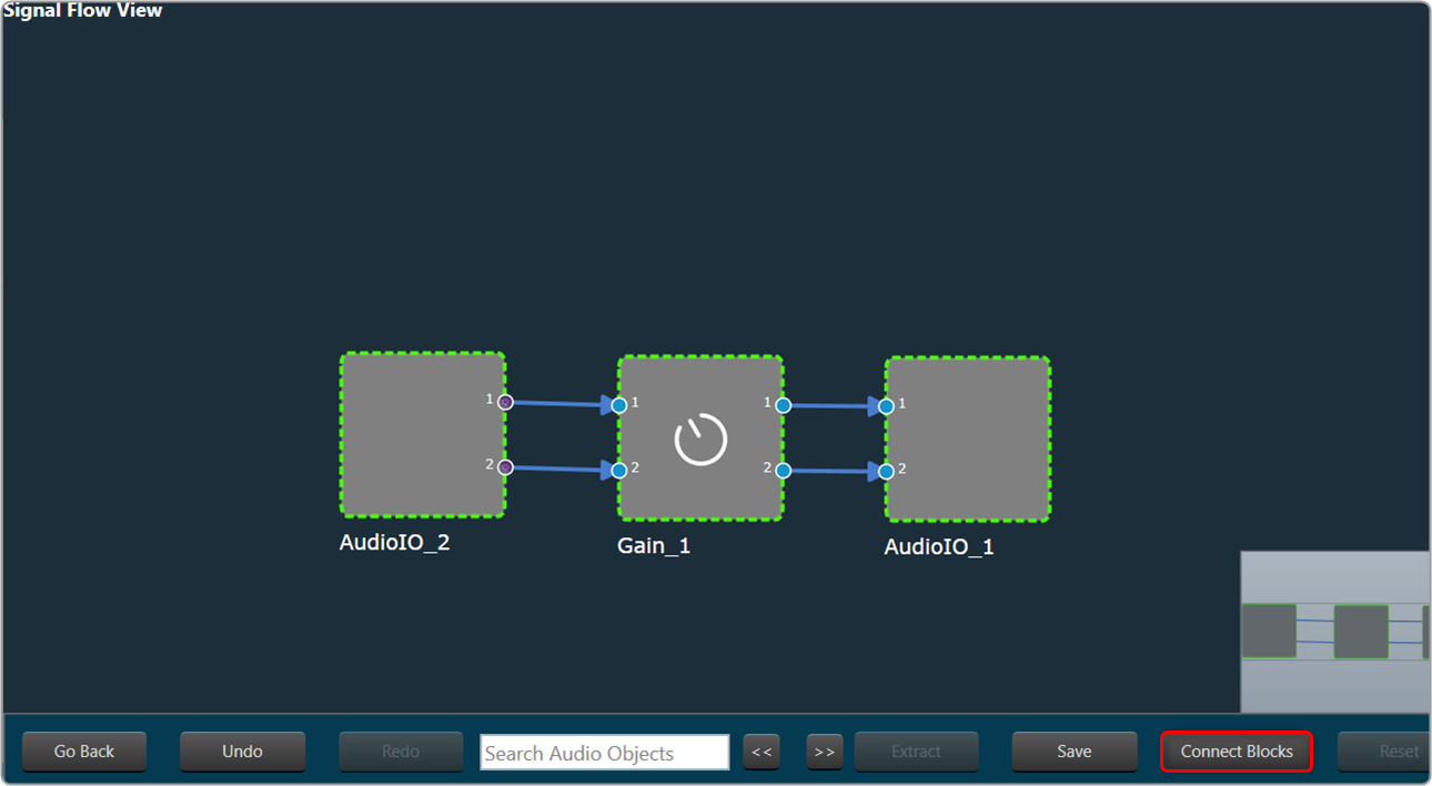
Now you have an input and output object, as well as an object to tune gain, invert, and mute parameters for each channel of signal flow designer. - Click Save to save the signal flow design and click Go Back.
- Click on Send Signal Flow.
Before performing the “Send Signal Flow” operation, make sure that the IVP is properly configured.
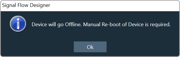
A pop-up message will ask you to reboot device.
- Switch to IVP RTA tab and click Reboot.
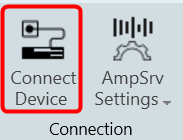
- Switch to Device Designer tab and click on Connect Device to connect to device.
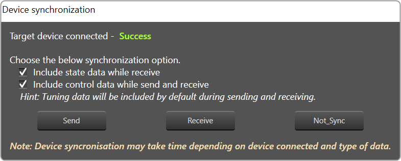
- Device synchronization dialogue box will appear, enable the desired synchronization option, and click Send.
If AmpSrv is unable to connect, close it and retry.
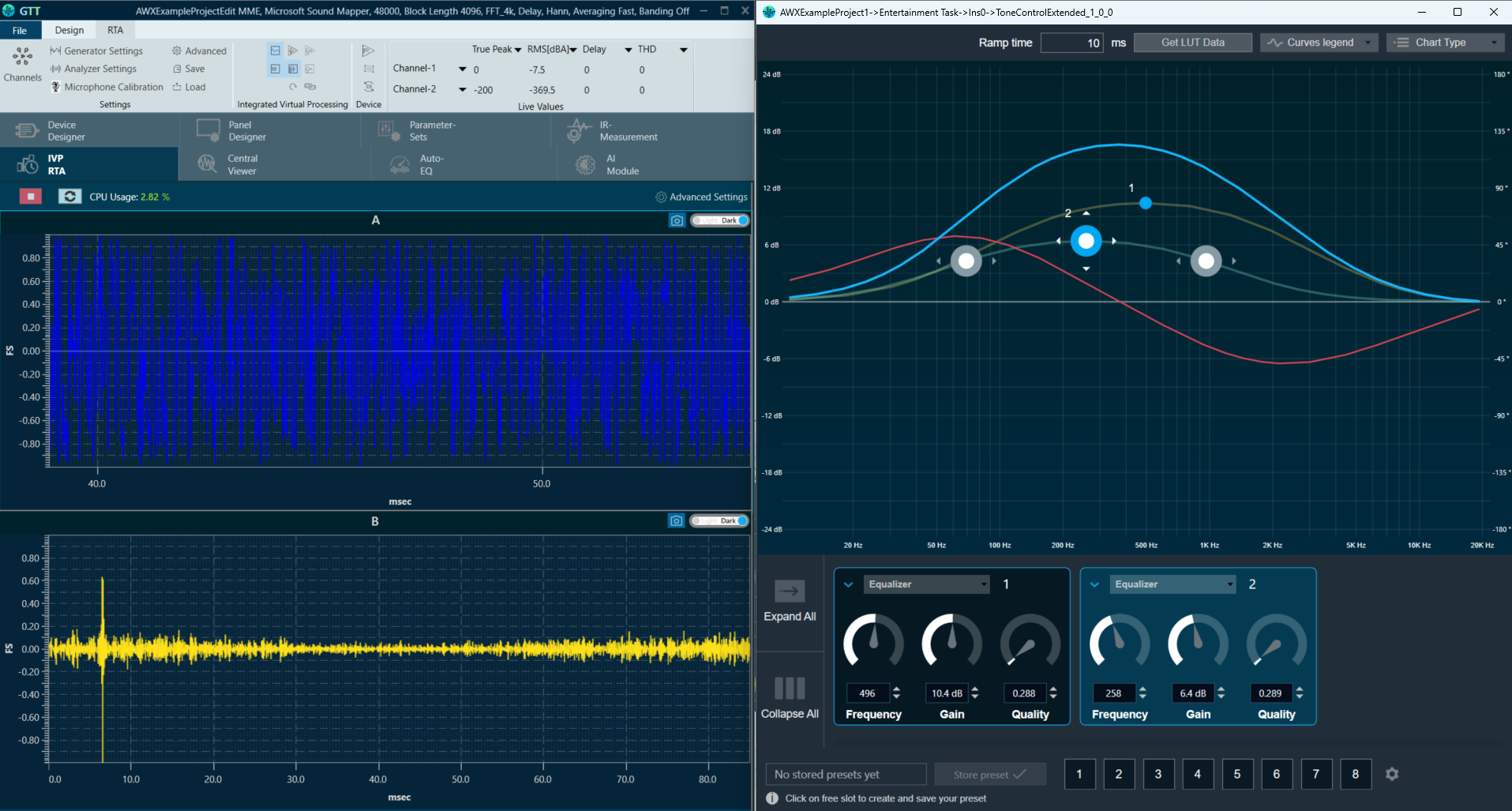
Now you can perform tuning on the IVP RTA.
A message “Signal flow successfully submitted” will be displayed. The Signal Flow will be sent to the virtual amplifier.
Using the Export option, you can export the signal flow design details. One .mcd file will be generated for master control data, and one .SFD file will be generated per instance per core.